2009 NISSAN LATIO torque
[x] Cancel search: torquePage 4108 of 4331
RF
N
O P
CAUTION:
• Before installing the sunroof motor assembly, be su re the link assembly is in the symmetrical and
fully closed position.
• Align the link notch with the hole of the guide track (fully closed: RH and LH).
1. Place the sunroof motor assembly flat onto the sunroof unit assembly surface.
2. Laterally move the assembly little by little so that the gear is completely engaged into the wire and there is no gap between the sunroof unit assembly and sunroof motor assembly.
3. Install the sunroof motor assembly screws, then connect the harness connector.
4. After installing, perform the initialization procedure. Refer to RF-11, " System Description " .
LINK ASSEMBLY
Removal 1. Remove sunroof unit assembly. Follow the SUNROOF UNIT ASSEMBLY procedure.
2. Remove screws, then remove rear drain assembly.
3. Remove sunroof motor assembly. Follo w the SUNROOF MOTOR ASSEMBLY procedure.
4. Remove link assembly from t he rear end of the sunroof frame.
Installation Installation is in the reverse order of removal.
Fitting Adjustment INFOID:0000000004307410
GAP ADJUSTMENT 1. Tilt up glass lid.
2. Loosen glass lid bolts, then tilt down glass lid.
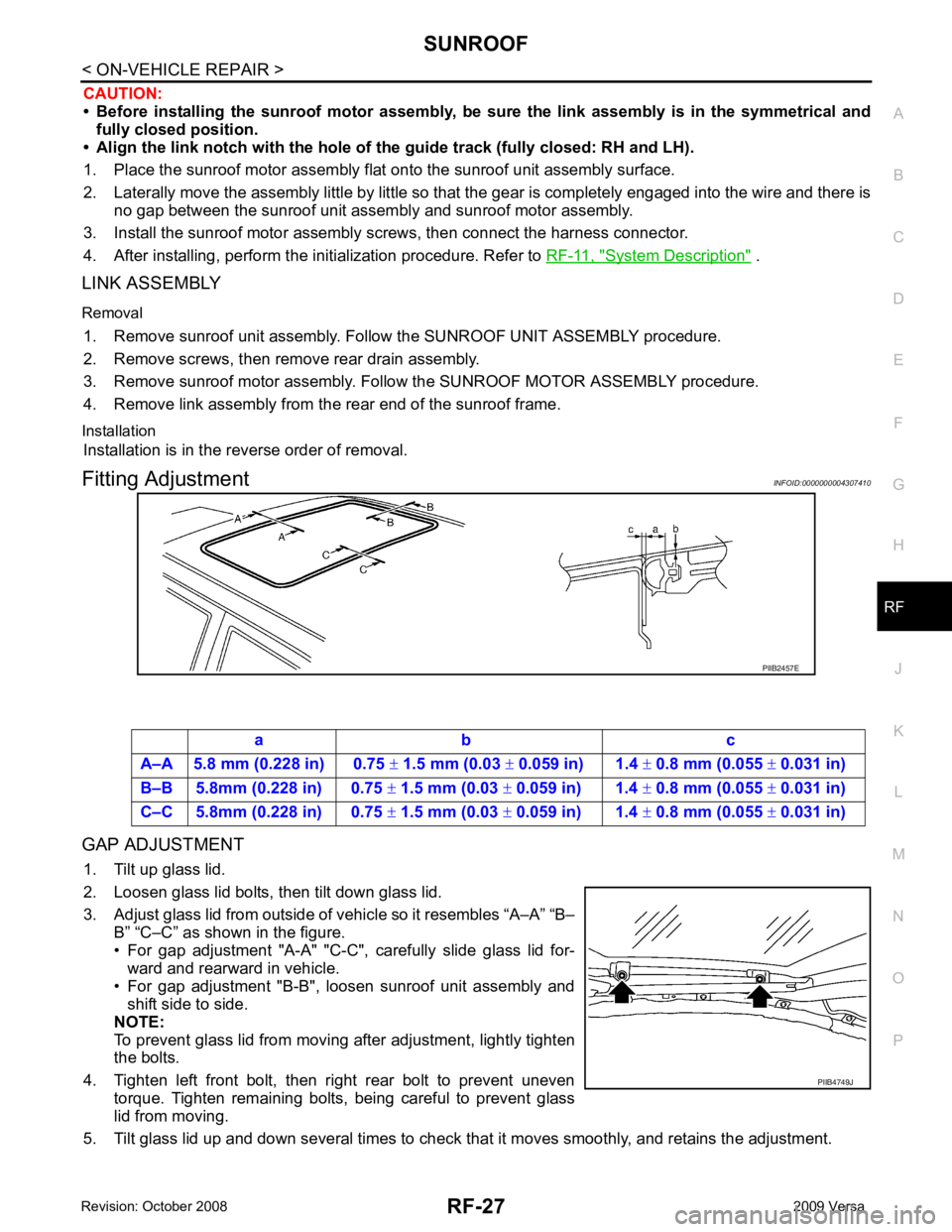
3. Adjust glass lid from outside of vehicle so it resembles “A–A” “B– B” “C–C” as shown in the figure.
• For gap adjustment "A-A" "C-C", carefully slide glass lid for- ward and rearward in vehicle.
• For gap adjustment "B-B", loosen sunroof unit assembly and
shift side to side.
NOTE:
To prevent glass lid from moving after adjustment, lightly tighten
the bolts.
4. Tighten left front bolt, then right rear bolt to prevent uneven torque. Tighten remaining bolts, being careful to prevent glass
lid from moving.
5. Tilt glass lid up and down several times to check that it moves smoothly, and retains the adjustment.
Page 4109 of 4331
RF-28< ON-VEHICLE REPAIR >
SUNROOF
HEIGHT ADJUSTMENT
1. Tilt up glass lid.
2. Loosen glass lid bolts, then tilt down glass lid.
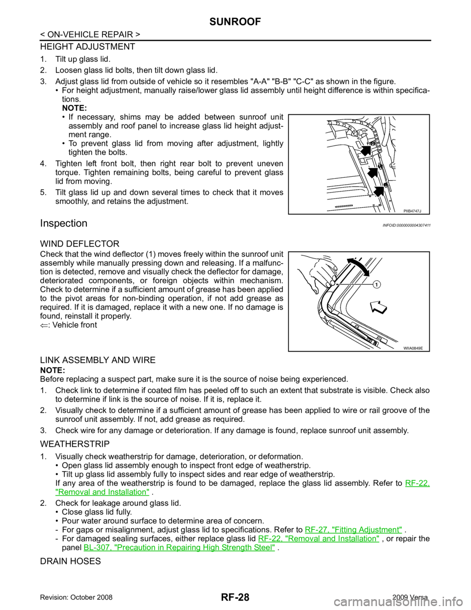
3. Adjust glass lid from outside of vehicle so it resembles "A-A" "B-B" "C-C" as shown in the figure.
• For height adjustment, manually raise/lower glass lid assembly until height difference is within specifica-
tions.
NOTE:
• If necessary, shims may be added between sunroof unit
assembly and roof panel to increase glass lid height adjust-
ment range.
• To prevent glass lid from moving after adjustment, lightly
tighten the bolts.
4. Tighten left front bolt, then right rear bolt to prevent uneven torque. Tighten remaining bolts, being careful to prevent glass
lid from moving.
5. Tilt glass lid up and down several times to check that it moves smoothly, and retains the adjustment.
Inspection INFOID:0000000004307411
WIND DEFLECTOR
Check that the wind deflector (1) moves freely within the sunroof unit
assembly while manually pressing down and releasing. If a malfunc-
tion is detected, remove and visually check the deflector for damage,
deteriorated components, or foreign objects within mechanism.
Check to determine if a sufficient amount of grease has been applied
to the pivot areas for non-binding operation, if not add grease as
required. If it is damaged, replace it with a new one. If no damage is
found, reinstall it properly.
⇐ : Vehicle front
LINK ASSEMBLY AND WIRE
NOTE:
Before replacing a suspect part, make sure it is the source of noise being experienced.
1. Check link to determine if coated film has peeled off to such an extent that substrate is visible. Check also
to determine if link is the source of noise. If it is, replace it.
2. Visually check to determine if a sufficient amount of grease has been applied to wire or rail groove of the
sunroof unit assembly. If not, add grease as required.
3. Check wire for any damage or deterioration. If any damage is found, replace sunroof unit assembly.
WEATHERSTRIP
1. Visually check weatherstrip for dam age, deterioration, or deformation.
• Open glass lid assembly enough to inspect front edge of weatherstrip.
• Tilt up glass lid assembly fully to in spect sides and rear edge of weatherstrip.
If any area of the weatherstrip is found to be damaged, replace the glass lid assembly. Refer to RF-22," Removal and Installation " .
2. Check for leakage around glass lid. • Close glass lid fully.
• Pour water around surface to determine area of concern.
- For gaps or misalignment, adjust glass lid to specifications. Refer to RF-27, " Fitting Adjustment " .
- For damaged sealing surfaces, either replace glass lid RF-22, " Removal and Installation " , or repair the
panel BL-307, " Precaution in Repairing High Strength Steel " .
DRAIN HOSES PIIB4747J
WIIA0849E
Page 4120 of 4331
RSU
N
O P
SHOCK ABSORBER
Removal and Installation INFOID:0000000004305881
REMOVAL 1. Remove wheel and tire using power tool.
2. Remove wheel sensor from wheel hub and bearing assembly and rear suspension beam. Refer to BRC-32 .
CAUTION:
Do not pull on wheel sensor harness.
3. Remove shock absorber mask from trunk side fini sher using a flat-bladed screwdriver. Refer to EI-53 .
CAUTION:
Wrap the tip of a screwdriver with cl oth to avoid damaging components.
4. Set jack under rear suspension beam.
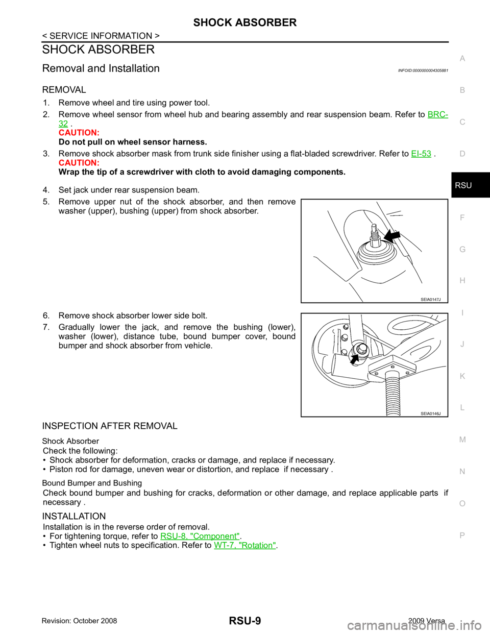
5. Remove upper nut of the shock absorber, and then remove washer (upper), bushing (upper) from shock absorber.
6. Remove shock absorber lower side bolt.
7. Gradually lower the jack, and remove the bushing (lower), washer (lower), distance tube, bound bumper cover, bound
bumper and shock absorber from vehicle.
INSPECTION AFTER REMOVAL
Shock Absorber Check the following:
• Shock absorber for deformation, cracks or damage, and replace if necessary.
• Piston rod for damage, uneven wear or di stortion, and replace if necessary .
Bound Bumper and Bushing Check bound bumper and bushing for cracks, deformation or other damage, and replace applicable parts if
necessary .
INSTALLATION Installation is in the reverse order of removal.
• For tightening torque, refer to RSU-8, " Component " .
• Tighten wheel nuts to specification. Refer to WT-7, " Rotation " .
Page 4122 of 4331
COIL SPRING
RSU-11
< SERVICE INFORMATION >
C
D
F
G H
I
J
K L
M A
B RSU
N
O P
COIL SPRING
Removal and Installation INFOID:0000000004305882
REMOVAL 1. Remove wheel and tire using power tool.
2. Remove wheel sensor from wheel hub and bearing assembly. Refer to BRC-32, " Removal and Installa-
tion " .
CAUTION:
Do not pull on wheel sensor harness.
3. Separate brake tube from wheel cylinder. Refer to BR-12, " Rear Brake Tube and Hose " .
4. Set jack under rear suspension beam.
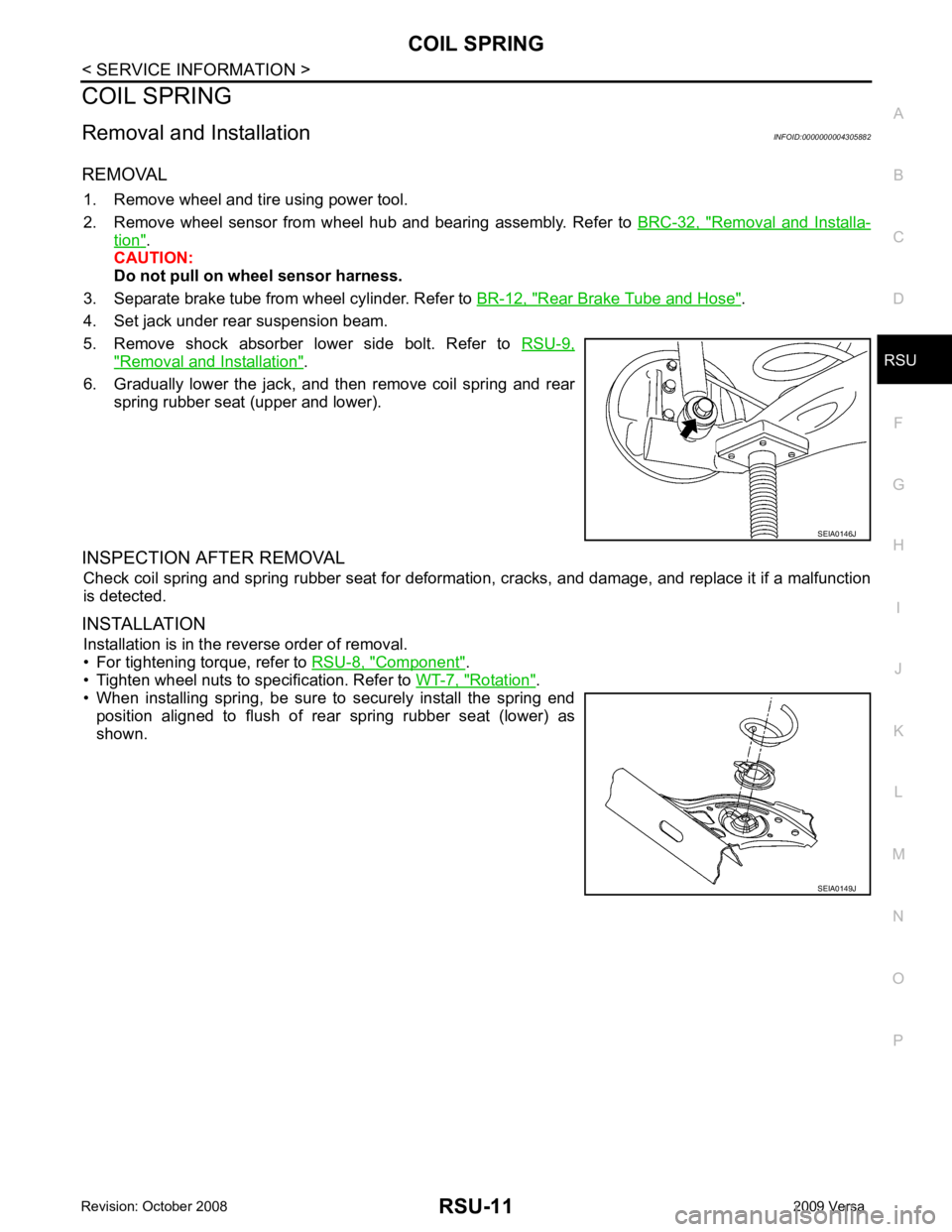
5. Remove shock absorber lower side bolt. Refer to RSU-9," Removal and Installation " .
6. Gradually lower the jack, and then remove coil spring and rear spring rubber seat (upper and lower).
INSPECTION AFTER REMOVAL Check coil spring and spring rubber seat for deformation, cracks, and damage, and replace it if a malfunction
is detected.
INSTALLATION Installation is in the reverse order of removal.
• For tightening torque, refer to RSU-8, " Component " .
• Tighten wheel nuts to specification. Refer to WT-7, " Rotation " .
• When installing spring, be sure to securely install the spring end
position aligned to flush of rear spring rubber seat (lower) as
shown. SEIA0146J
SEIA0149J
Page 4123 of 4331
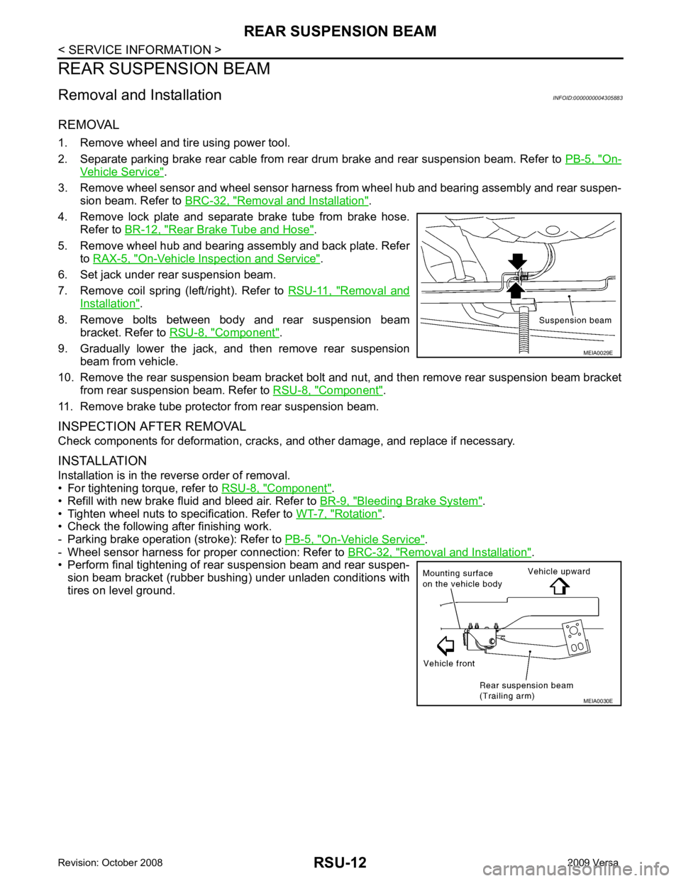
On-
Vehicle Service " .
3. Remove wheel sensor and wheel sensor harness from wheel hub and bearing assembly and rear suspen-
sion beam. Refer to BRC-32, " Removal and Installation " .
4. Remove lock plate and separate brake tube from brake hose. Refer to BR-12, " Rear Brake Tube and Hose " .
5. Remove wheel hub and bearing assembly and back plate. Refer to RAX-5, " On-Vehicle Inspection and Service " .
6. Set jack under rear suspension beam.
7. Remove coil spring (left/right). Refer to RSU-11, " Removal and
Installation " .
8. Remove bolts between body and rear suspension beam bracket. Refer to RSU-8, " Component " .
9. Gradually lower the jack, and then remove rear suspension beam from vehicle.
10. Remove the rear suspension beam bracket bolt and nut, and then remove rear suspension beam bracket
from rear suspension beam. Refer to RSU-8, " Component " .
11. Remove brake tube protector from rear suspension beam.
INSPECTION AFTER REMOVAL
Check components for deformation, cracks, and other damage, and replace if necessary.
INSTALLATION
Installation is in the reverse order of removal.
• For tightening torque, refer to RSU-8, " Component " .
• Refill with new brake fluid and bleed air. Refer to BR-9, " Bleeding Brake System " .
• Tighten wheel nuts to specification. Refer to WT-7, " Rotation " .
• Check the following after finishing work.
- Parking brake operation (stroke): Refer to PB-5, " On-Vehicle Service " .
- Wheel sensor harness for proper connection: Refer to BRC-32, " Removal and Installation " .
• Perform final tightening of rear suspension beam and rear suspen-
sion beam bracket (rubber bushing) under unladen conditions with
tires on level ground. MEIA0030E
Page 4166 of 4331
SE
N
O P
• Handle trim, molding instruments, grille, etc. carefully during removing or installing. Be careful not to oil or
damage them.
• Apply sealing compound where necessary when installing parts.
• When applying sealing compound, be careful that the sealing compound does not protrude from parts.
• When replacing any metal parts (for example body outer panel, member, etc.), be sure to take rust preven-
tion measures.
Precaution INFOID:0000000004306501
• When removing or disassembling any part, be careful not to damage or deform it. Protect parts which may
get in the way with cloth.
• When removing parts with a screwdriver or other tool , protect parts by wrapping tools with vinyl or tape.
• Keep removed parts protected with cloth.
• If a clip is deformed or damaged, replace it.
• If an unreusable part is removed, replace it with a new one.
• Tighten bolts and nuts firmly to the specified torque.
• After re-assembly has been completed, make sure each part functions correctly.
• Remove stains in the following way.
Water-soluble stains:
Dip a soft cloth in warm water, and then squeeze it tight ly. After wiping the stain, wipe with a soft dry cloth.
Oil stain:
Dissolve a synthetic detergent in warm water (density of 2 to 3% or less), dip the cloth, then clean off the stain
with the cloth. Next, dip the cloth in fresh water and squeeze it tightly. Then clean off the detergent completely.
Then wipe the area with a soft dry cloth.
• Do not use any organic solvent, such as thinner or benzine.
Page 4241 of 4331
STC
N
O P
CONTENTS
STEERING CONTROL SYSTEM
EPS
SERVICE INFORMATION .. ..........................
2
PRECAUTIONS .............................................. .....2
Precaution for Supplemental Restraint System
(SRS) "AIR BAG" and "SEAT BELT PRE-TEN-
SIONER" ............................................................. ......
2
Precaution Necessary fo r Steering Wheel Rota-
tion After Battery Disconnect ............................... ......
2
Service Notice or Precau tion for EPS System ..........3
EPS SYSTEM ... .............................................. .....4
System Description ............................................. ......4
Schematic ........................................................... ......5
CAN Communication ........................................... ......5
TROUBLE DIAGNOSIS ................................. .....6
Fail-Safe Function ............................................... ......6
How to Perform Trouble Diagnosis ..................... ......6
Component Parts Location .................................. ......7
Wiring Diagram - EPS - ... ..........................................8
EPS Control Unit Input/O utput Signal Reference
Value ................................................................... ......
9 EPS Terminal and Reference Value ....................
....10
CONSULT-III Function ( EPS) ..................................11
Symptom Chart .................................................... ....13
TROUBLE DIAGNOSIS FOR SYSTEM ............ 14
DTC C1601 BATTERY VOLT .............................. ....14
DTC C1604 TORQUE SENSOR ......................... ....15
DTC C1606 EPS MOTOR ................................... ....16
DTC C1607 EEPROM ......................................... ....17
DTC C1608 CONTROL UNIT .............................. ....17
DTC C1609 CAN VHCL SPEED ......................... ....18
DTC C1610 CAN ENG RPM ............................... ....19
DTC U1000 CAN COMM CIRCUIT ..................... ....19
Component Inspection ......................................... ....19
TROUBLE DIAGNOSIS FOR SYMPTOMS ...... 21
EPS Warning Lamp Does Not Turn ON ..................21
EPS Warning Lamp Does Not Turn OFF ................21
Steering Wheel Turning Force Is Heavy or Light . ....22
Unbalance Steering Wheel Turning Force and Re-
turn Between Right and Left ................................ ....
23
Unbalance Steering Wheel Turning Force (Torque
Variation) ............................................................. ....
24
Page 4251 of 4331
STC
N
O P
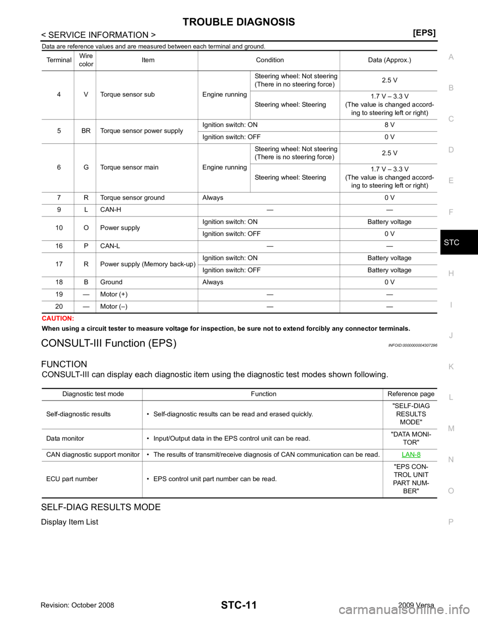
Data are reference values and are
measured between each terminal and ground.
CAUTION:
When using a circuit tester to measure voltage for inspection , be sure not to extend forcibly any connector terminals.
CONSULT-III Function (EPS) INFOID:0000000004307296
FUNCTION CONSULT-III can display each diagnostic item using the diagnostic test modes shown following.
SELF-DIAG RESULTS MODE
Display Item List Terminal
Wire
color Item Condition Data (Approx.)
4 V Torque sensor sub Engine running Steering wheel: Not steering
(There in no steering force) 2.5 V
Steering wheel: Steering 1.7 V – 3.3 V
(The value is changed accord- ing to steering left or right)
5 BR Torque sensor power supply Ignition switch: ON 8 V
Ignition switch: OFF 0 V
6 G Torque sensor main Engine running Steering wheel: Not steering
(There is no steering force) 2.5 V
Steering wheel: Steering 1.7 V – 3.3 V
(The value is changed accord- ing to steering left or right)
7 R Torque sensor ground Always 0 V
9 L CAN-H — —
10 O Power supply Ignition switch: ON Battery voltage
Ignition switch: OFF 0 V
16 P CAN-L — —
17 R Power supply (Memory back-up) Ignition switch: ON Battery voltage
Ignition switch: OFF Battery voltage
18 B Ground Always 0 V
19 — Motor (+) — —
20 — Motor (–) — — Diagnostic test mode Function Reference page
Self-diagnostic results • Self-diagnostic results can be read and erased quickly. "SELF-DIAG
RESULTS MODE"
Data monitor • Inpu t/Output data in the EPS control unit can be read. "DATA MONI-
TOR"
CAN diagnostic support monitor • The results of transmit/receive diagnosis of CAN communication can be read. LAN-8ECU part number • EPS control unit
part number can be read. "EPS CON-
TROL UNIT
PART NUM- BER"