Page 4042 of 4331
PG
N
O P
STM CVT Step Motor
STOP/L LT Stop Lamp
TCV AT Torque Converter Clutch Solenoid Valve
TCV CVT Torque Converter Clutch Solenoid Valve
T/LID BL Trunk Lid Opener
T/WARN WT Low Tire Pr essure Warning System
TAIL/L LT Parking, License and Tail Lamps
TPS1 EC Throttle Position Sensor
TPS2 EC Throttle Position Sensor
TPS3 EC Throttle Position Sensor
TURN LT Turn Signal and Hazard Warning Lamps
VEHSEC BL Vehicle Security (Theft Warning) System
VENT/V EC EVAP Canister Vent Control Valve
VSSA/T AT Vehicle Speed Sensor A/T (Revolution Sensor)
VSSMTR AT Vehicle Speed Sensor MTR
WARN DI Warning Lamps
WINDOW GW Power Window
WIP/R WW Rear Wiper and Washer
WIPER WW Front Wiper and Washer
Page 4060 of 4331
PS-4< SERVICE INFORMATION >
PREPARATION
PREPARATION
Special Service Tool INFOID:0000000004305928
The actual shapes of K ent-Moore tools may differ from thos e of special tools illustrated here.
Commercial Service Tool INFOID:0000000004305929
Tool number
(Kent-Moore No.)
Tool name Description
ST3127S000
(J-25742-1)
Preload gauge
(J-25765-A)
1. GG91030000
Torque wrench
2. HT62940000
( — )
Socket adapter (1/2")
3. HT62900000
( — )
Socket adapter (3/8") Inspecting rotating torque for steering column
assembly and pinion assembly
KV40107300
( — )
Boot Band crimping tool Installing boot bands
KV48103400
( — )
Preload adapter Inspecting of rotating torque for pinion assem-
bly S-NT541
ZZA1229D
ZZA0824D
Tool number
Tool name Description
Spring gauge Inspecting steering wheel turning force and
power steering gear linkage
Power tool Removing nuts and bolts LST025
PBIC0190E
Page 4061 of 4331

PS
N
O P
NOISE, VIBRATION AND HARSHN
ESS (NVH) TROUBLESHOOTING
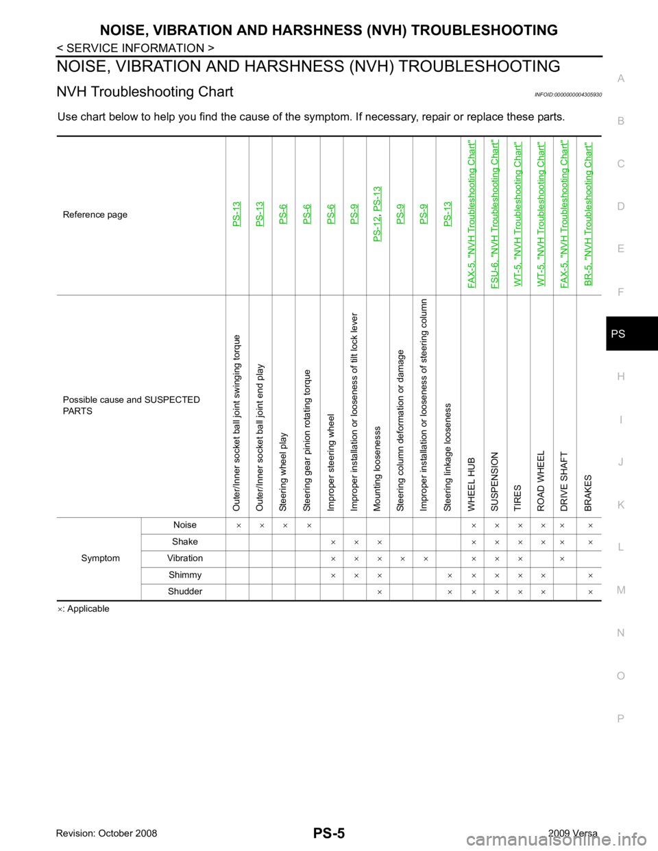
NVH Troubleshooting Chart INFOID:0000000004305930
Use chart below to help you find the cause of the symptom. If necessary, repair or replace these parts.
× : ApplicableReference pagePS-13PS-13PS-6PS-6PS-6PS-9
PS-12
,
PS-13PS-9PS-9PS-13
FAX-5, "
NVH Troubleshooting Chart
"
FSU-6, "
NVH Troubleshooting Chart
"
WT-5, "
NVH Troubleshooting Chart
"
WT-5, "
NVH Troubleshooting Chart
"
FAX-5, "
NVH Troubleshooting Chart
"
BR-5, "
NVH Troubleshooting Chart
" Possible cause and SUSPECTED
PARTS
Outer/Inner socket ball joint swinging torque
Outer/Inner socket ball joint end play
Steering wheel play
Steering gear pinion rotating torque
Improper steering wheel
Improper installation or looseness of tilt lock lever
Mounting loosenesss
Steering column deformation or damage
Improper installation or looseness of steering column
Steering linkage looseness
WHEEL HUB
SUSPENSION
TIRES
ROAD WHEEL
DRIVE SHAFT
BRAKES
Symptom Noise
× × × × × × × × × ×
Shake × × × × × × × × ×
Vibration × × × × × × × × ×
Shimmy × × × × × × × × ×
Shudder × × × × × × ×
Page 4066 of 4331
CONSULT-III Function (EPS) " .
Steering column
length “L” Minimum 462.1 mm (18.19 in)
Nominal 464.1 mm (18.27 in)
Maximum 466.1 mm (18.35 in)
Tool number : ST3127S000 (J-25742-1)
Rotating torque : 0 - 2.1 N·m (0 - 0.21 kg-m, 0 - 18 in-lb) SGIA1295E
Page 4071 of 4331

PS
N
O P
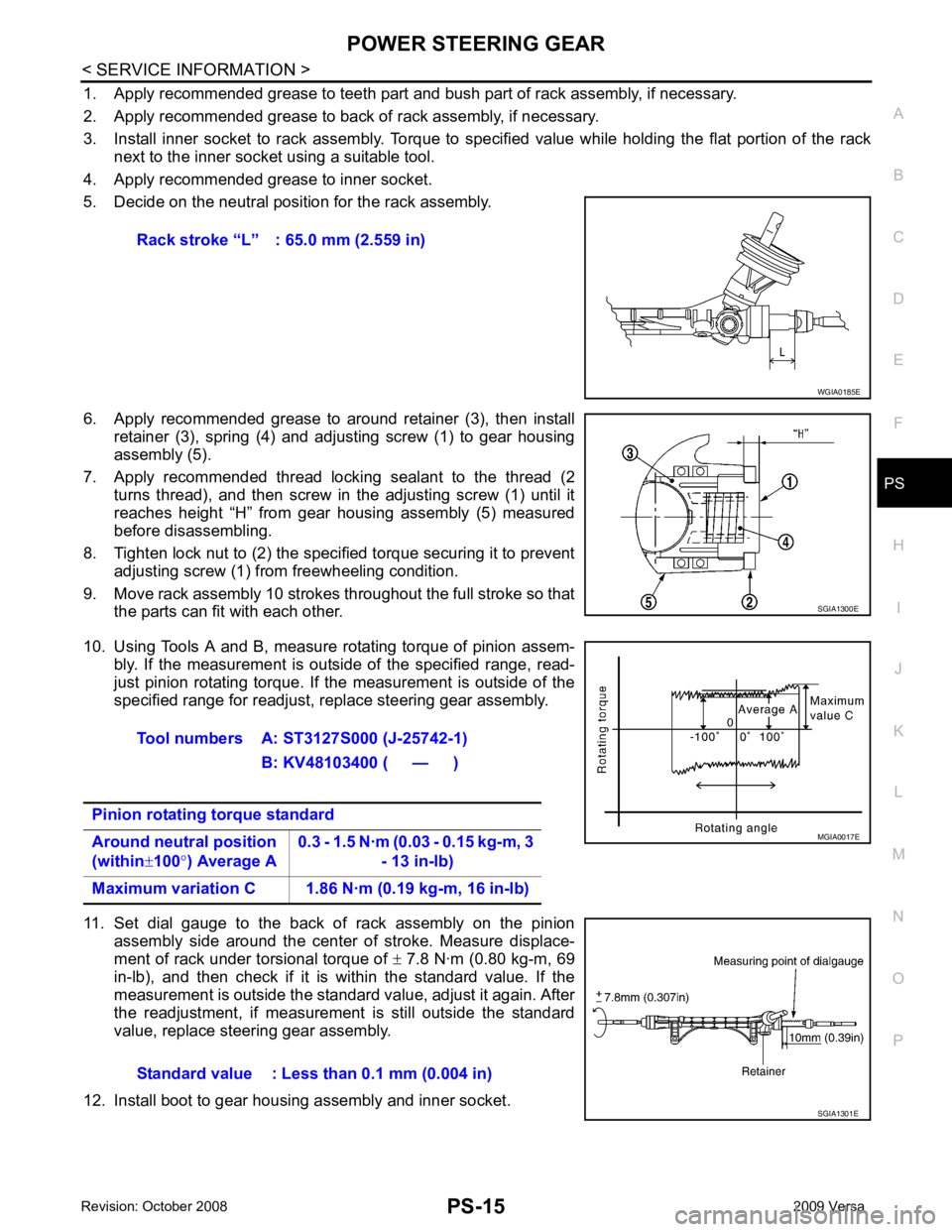
1. Apply recommended grease to teeth part and bush part of rack assembly, if necessary.
2. Apply recommended grease to back of rack assembly, if necessary.
3. Install inner socket to rack assembly. Torque to specified value while holding the flat portion of the rack next to the inner socket using a suitable tool.
4. Apply recommended grease to inner socket.
5. Decide on the neutral position for the rack assembly.
6. Apply recommended grease to around retainer (3), then install retainer (3), spring (4) and adjusting screw (1) to gear housing
assembly (5).
7. Apply recommended thread locking sealant to the thread (2 turns thread), and then screw in the adjusting screw (1) until it
reaches height “H” from gear housing assembly (5) measured
before disassembling.
8. Tighten lock nut to (2) the specified torque securing it to prevent adjusting screw (1) from freewheeling condition.
9. Move rack assembly 10 strokes throughout the full stroke so that the parts can fit with each other.
10. Using Tools A and B, measure rotating torque of pinion assem- bly. If the measurement is outside of the specified range, read-
just pinion rotating torque. If the measurement is outside of the
specified range for readjust, replace steering gear assembly.
11. Set dial gauge to the back of rack assembly on the pinion assembly side around the center of stroke. Measure displace-
ment of rack under torsional torque of ± 7.8 N·m (0.80 kg-m, 69
in-lb), and then check if it is within the standard value. If the
measurement is outside the standard value, adjust it again. After
the readjustment, if measurement is still outside the standard
value, replace steering gear assembly.
12. Install boot to gear housing assembly and inner socket. Rack stroke “L” : 65.0 mm (2.559 in)
Page 4073 of 4331

SERVICE DATA AND SPECIFICATIONS (SDS)
PS-17
< SERVICE INFORMATION >
C
D E
F
H I
J
K L
M A
B PS
N
O
P
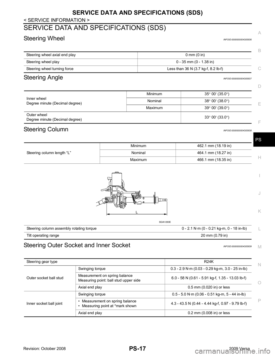
SERVICE DATA AND SPECIFICATIONS (SDS)
Steering Wheel INFOID:0000000004305936
Steering Angle INFOID:0000000004305937
Steering Column INFOID:0000000004305938
Steering Outer Socket and Inner Socket INFOID:0000000004305939
Steering wheel axial end play 0 mm (0 in)
Steering wheel play 0 - 35 mm (0 - 1.38 in)
Steering wheel turning force Less than 36 N (3.7 kg-f, 8.2 lb-f) Inner wheel
Degree minute (Decimal degree) Minimum 35
° 00 ′ (35.0 °)
Nominal 38 ° 00 ′ (38.0 °)
Maximum 39 ° 00 ′ (39.0 °)
Outer wheel
Degree minute (Decimal degree) 33
° 00 ′ (33.0 °) Steering column length “L”
Minimum 462.1 mm (18.19 in)
Nominal 464.1 mm (18.27 in)
Maximum 466.1 mm (18.35 in)
Steering column assembly rotating torque 0 - 2.1 N·m (0 - 0.21 kg-m, 0 - 18 in-lb)
Tilt operating range 20 mm (0.79 in)SGIA1293E
Steering gear type R24K
Outer socket ball stud Swinging torque 0.3 - 2.9 N·m (0.03 - 0.29 kg-m, 3.0 - 25 in-lb)
Measurement on spring balance
Measuring point: ball stud upper side 6.0 - 58 N (0.61 - 5.91 kg-f, 1.35 - 13.03 lb-f)
Axial end play 0.5 mm (0.020 in) or less
Inner socket ball joint Swinging torque 0.5 - 5.0 N·m (0.06 - 0.51 kg-m, 5 - 44 in-lb)
• Measurement on spring balance
• Measuring point at *mark shown 4.3 - 43.5 N (0.44 - 4.44 kg-f, 0.97 - 9.79 lb-f)
Axial end play 0.2 mm (0.008 in) or less
Page 4074 of 4331
PS-18< SERVICE INFORMATION >
SERVICE DATA AND SPECIFICATIONS (SDS)
Steering Gear INFOID:0000000004305940
Inner socket length “L”
57.8 mm (2.276 in)
Steering gear type
R24KSGIA0950E
Steering gear model R24K
Rack neutral position, dimension “L ” (rack stroke) 65. 0 mm (2.559 in)
Pinion rotating torque
standard Around neutral position
(within ± 100 °) Average A 0.3 - 1.5 N·m (0.03 - 0.15 kg-m, 3 - 13 in-lb)
Maximum variation C 1.86 N· m (0.19 kg-m, 16 in-lb) WGIA0185E
MGIA0017E
Page 4084 of 4331

RF
N
O P
• When removing or disassembling any part, be careful
not to damage or deform it. Protect parts which may
get in the way with cloth.
• When removing parts with a screwdriver or other tool , protect parts by wrapping them with vinyl or tape.
• Keep removed parts protected with cloth.
• If a clip is deformed or damaged, replace it.
• If an unreusable part is removed, replace it with a new one.
• Tighten bolts and nuts firmly to the specified torque.
• After re-assembly has been completed, make sure each part functions correctly.
• Remove stains in the following way.
Water-soluble stains:
Dip a soft cloth in warm water, and then squeeze it tight ly. After wiping the stain, wipe with a soft dry cloth.
Oil stain:
Dissolve a synthetic detergent in warm water (density of 2 to 3% or less), dip the cloth, then clean off the stain
with the cloth. Next, dip the cloth in fresh water and squeeze it tightly. Then clean off the detergent completely.
Then wipe the area with a soft dry cloth.
• Do not use any organic solvent, such as thinner or benzine.