2009 NISSAN LATIO torque
[x] Cancel search: torquePage 1299 of 4331
![NISSAN LATIO 2009 Service Repair Manual TRANSAXLE ASSEMBLY
CVT-355
< SERVICE INFORMATION >
[RE0F08B] D
E
F
G H
I
J
K L
M A
B CVT
N
O P
4. Remove the four drive plate to torque converter nuts.
NOTE:
Rotate the crankshaft clockwise as vi NISSAN LATIO 2009 Service Repair Manual TRANSAXLE ASSEMBLY
CVT-355
< SERVICE INFORMATION >
[RE0F08B] D
E
F
G H
I
J
K L
M A
B CVT
N
O P
4. Remove the four drive plate to torque converter nuts.
NOTE:
Rotate the crankshaft clockwise as vi](/manual-img/5/57359/w960_57359-1298.png)
TRANSAXLE ASSEMBLY
CVT-355
< SERVICE INFORMATION >
[RE0F08B] D
E
F
G H
I
J
K L
M A
B CVT
N
O P
4. Remove the four drive plate to torque converter nuts.
NOTE:
Rotate the crankshaft clockwise as viewed from front of engine
for access to drive plate to torque converter nuts.
5. Put matching marks on the drive plate and torque converter alignment stud. CAUTION:
For matching marks, use paint. Never dama ge the drive plate or torque converter.
6. Remove the transaxle to engine and engine to transaxle bolts.
7. Separate the transaxle from the engine.
8. If necessary, remove the following from the transaxle: • CVT fluid charging pipe
• Engine mounting bracket (LH)
• Fluid cooler tubes
• Air breather hose
• Any necessary brackets
INSTALLATION Installation is in the reverse order of removal.
CAUTION:
• When replacing an engine or transmission you mu st make sure any dowels are installed correctly
during re-assembly.
• Improper alignment caused by missing dowels m ay cause vibration, oil leaks or breakage of drive
train components.
• Do not reuse O-rings and copper washers.
• When turning crankshaft, turn it clockwise as viewed from the front of the engine.
• When tightening the nuts for the torque converter while securing the crankshaft pulley bolt, be sure
to confirm the tightening torque of the crankshaft pulley bolt. Refer to EM-160 .
• After converter is installed to drive plate, ro tate crankshaft several turns to check that transaxle
rotates freely without binding.
• When installing the torque converter to the transaxle measure dis- tance A. WCIA0616E
Distance A: 14.4 mm (0.57 in) or more
WCIA0617E
Page 1300 of 4331
![NISSAN LATIO 2009 Service Repair Manual CVT-356< SERVICE INFORMATION >
[RE0F08B]
TRANSAXLE ASSEMBLY
• When installing the cooler outlet tube (1) to the transaxle assembly (2), align the cooler tube bracket (A) against the transax NISSAN LATIO 2009 Service Repair Manual CVT-356< SERVICE INFORMATION >
[RE0F08B]
TRANSAXLE ASSEMBLY
• When installing the cooler outlet tube (1) to the transaxle assembly (2), align the cooler tube bracket (A) against the transax](/manual-img/5/57359/w960_57359-1299.png)
CVT-356< SERVICE INFORMATION >
[RE0F08B]
TRANSAXLE ASSEMBLY
• When installing the cooler outlet tube (1) to the transaxle assembly (2), align the cooler tube bracket (A) against the transaxle as
shown.
• When installing the transaxle to the engine, align t he matching mark on the drive plate with the matching
mark on the torque converter alignment stud.
• When securing the transaxle to the engine, attach the bolts in
accordance with the following standard.
• When installing the drive plate to torque converter nuts, tighten them temporarily. Then tighten the nuts to the specified torque.
• After completing installation check for fluid level, fluid leakage, and the positions of CVT. Refer to CVT-196," Checking CVT Fluid " ,
CVT-345, " Adjustment of CVT Position " and
CVT-345, " Checking of CVT Position " .
• When replacing the CVT assembly, erase EEP ROM in TCM. Refer to CVT-190, " Service After Replacing
TCM and Transaxle Assembly " . WCIA0618E
Bolt No. 1 (Transaxle to engine) 2 (Engine to transaxle)
Number of bolts 2 7
Bolt length
“A” mm (in) 55 (2.17) 50 (1.97)
Tightening torque
N·m (kg-m, ft-lb) 62 (6.3, 46) WCIA0619E
Converter nuts: : 51 N·m (5.2 kg-m, 38 ft-lb)
WCIA0616E
Page 1851 of 4331

EC
NP
O
•
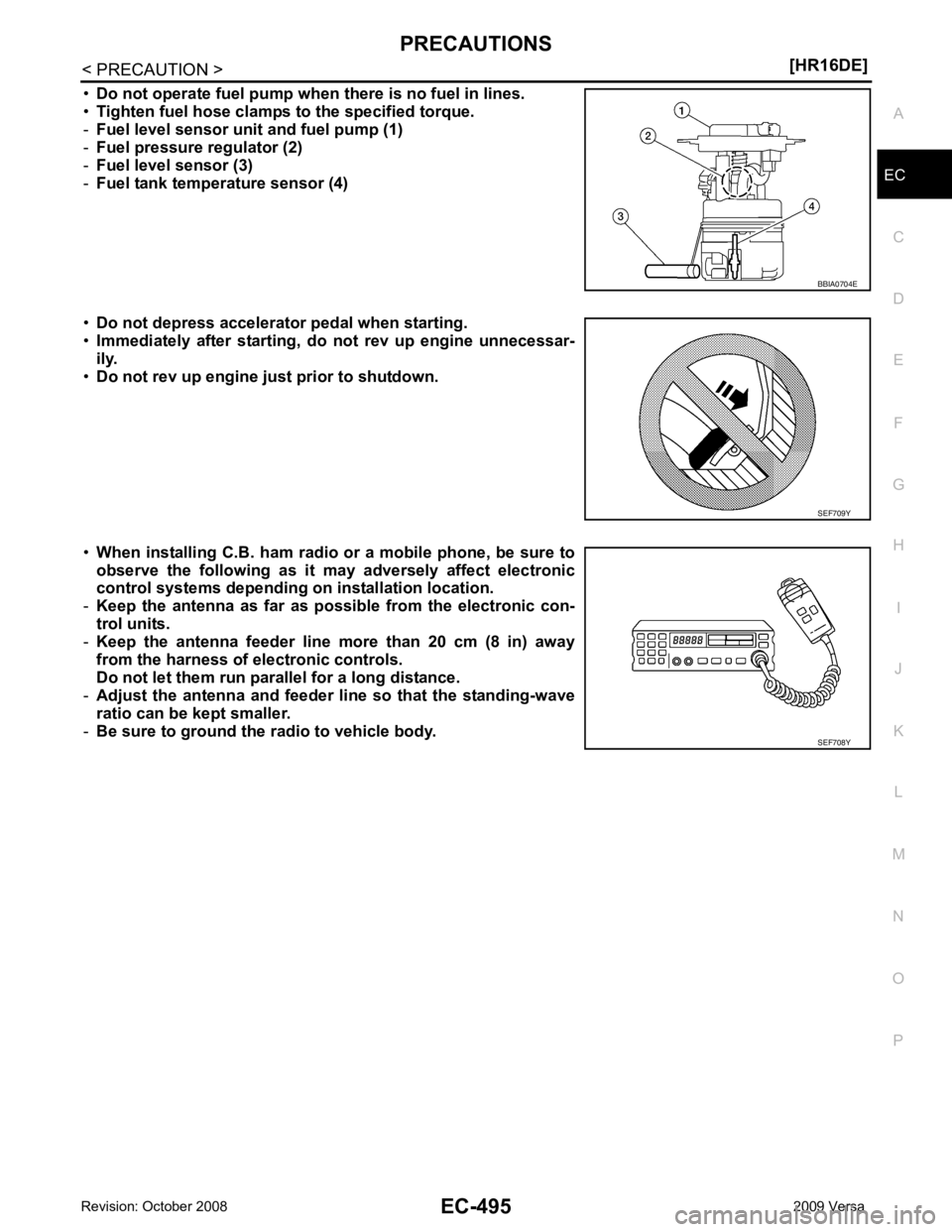
Do not operate fuel pump when there is no fuel in lines.
• Tighten fuel hose clamps to the specified torque.
- Fuel level sensor unit and fuel pump (1)
- Fuel pressure regulator (2)
- Fuel level sensor (3)
- Fuel tank temperature sensor (4)
• Do not depress accelerator pedal when starting.
• Immediately after starting, do not rev up engine unnecessar-
ily.
• Do not rev up engine ju st prior to shutdown.
• When installing C.B. ham radio or a mobile phone, be sure to
observe the following as it may adversely affect electronic
control systems depending on installation location.
- Keep the antenna as far as possible from the electronic con-
trol units.
- Keep the antenna feeder line more than 20 cm (8 in) away
from the harness of electronic controls.
Do not let them run para llel for a long distance.
- Adjust the antenna and feeder line so that the standing-wave
ratio can be kept smaller.
- Be sure to ground the radio to vehicle body.
Page 1855 of 4331

EC
NP
O
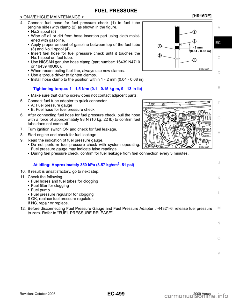
4. Connect fuel hose for fuel pressure check (1) to fuel tube
(engine side) with clamp (2) as shown in the figure.
• No.2 spool (5)
• Wipe off oil or dirt from hose insertion part using cloth moist-
ened with gasoline.
• Apply proper amount of gasoline between top of the fuel tube
(3) and No.1 spool (4).
• Insert fuel hose for fuel pressure check until it touches the No.1 spool on fuel tube.
• Use NISSAN genuine hose clamp (part number: 16439 N4710 or 16439 40U00).
• When reconnecting fuel line, always use new clamps.
• Use a torque driver to tighten clamps.
• Install hose clamp to the positi on within 1 - 2 mm (0.04 - 0.08 in).
• Make sure that clamp screw does not contact adjacent parts.
5. Connect fuel tube adapter to quick connector. • A: Fuel pressure gauge
• B: Fuel hose for fuel pressure check
6. After connecting fuel hose for fuel pressure check, pull the hose with a force of approximately 98 N (10 kg, 22 lb) to confirm fuel
tube does not come off.
7. Turn ignition switch ON and check for fuel leakage.
8. Start engine and check for fuel leakage.
9. Read the indication of fuel pressure gauge. • Do not perform fuel pressure check with system operating.
Fuel pressure gauge may indicate false readings.
• During fuel pressure check, confirm for f uel leakage from fuel connection every 3 minutes.
10. If result is unsatisfactory, go to next step.
11. Check the following. • Fuel hoses and fuel tubes for clogging
• Fuel filter for clogging
• Fuel pump
• Fuel pressure regulator for clogging
If OK, replace fuel pressure regulator.
If NG, repair or replace.
12. Before disconnecting Fuel Pressure Gauge and Fuel Pressure Adapter J-44321-6, release fuel pressure
to zero. Refer to "FUEL PRESSURE RELEASE". Tightening torque: 1 - 1.5 N·m
(0.1 - 0.15 kg-m, 9 - 13 in-lb)
At idling: Approximately 350 kPa (3.57 kg/cm 2
, 51 psi) PBIB2984E
Page 1871 of 4331
![NISSAN LATIO 2009 Service Repair Manual PRECAUTIONS
EC-515
< SERVICE INFOMATION >
[MR TYPE 1] C
D E
F
G H
I
J
K L
M A EC
NP
O
•
Do not operate fuel pump when there is no fuel in lines.
• Tighten fuel hose clamps to the specified torqu NISSAN LATIO 2009 Service Repair Manual PRECAUTIONS
EC-515
< SERVICE INFOMATION >
[MR TYPE 1] C
D E
F
G H
I
J
K L
M A EC
NP
O
•
Do not operate fuel pump when there is no fuel in lines.
• Tighten fuel hose clamps to the specified torqu](/manual-img/5/57359/w960_57359-1870.png)
PRECAUTIONS
EC-515
< SERVICE INFOMATION >
[MR TYPE 1] C
D E
F
G H
I
J
K L
M A EC
NP
O
•
Do not operate fuel pump when there is no fuel in lines.
• Tighten fuel hose clamps to the specified torque.
- Fuel level sensor unit and fuel pump (1)
- Fuel pressure regulator (2)
- Fuel level sensor (3)
- Fuel tank temperature sensor (4)
• Do not depress accelerator pedal when starting.
• Immediately after starting, do not rev up engine unnecessar-
ily.
• Do not rev up engine ju st prior to shutdown.
• When installing C.B. ham radio or a mobile phone, be sure to
observe the following as it may adversely affect electronic
control systems depending on installation location.
- Keep the antenna as far as possible from the electronic con-
trol units.
- Keep the antenna feeder line more than 20 cm (8 in) away
from the harness of electronic controls.
Do not let them run para llel for a long distance.
- Adjust the antenna and feeder line so that the standing-wave
radio can be kept smaller.
- Be sure to ground the radio to vehicle body. BBIA0704E
SEF709Y
SEF708Y
Page 1931 of 4331

EC
NP
O
1. Remove fuel pump fuse (1) located in IPDM E/R (2).
• : Vehicle front
2. Start engine.
3. After engine stalls, crank it two or three times to release all fuel pressure.
4. Turn ignition switch OFF.
5. Reinstall fuel pump fuse after servicing fuel system.
FUEL PRESSURE CHECK CAUTION:
Before disconnecting fuel line, release fuel pressure from fuel line to eliminate danger.
NOTE:
• Prepare pans or saucers under the disconnected fuel line because the fuel may spill out. The fuel
pressure cannot be completely released because C11 models do not have fuel return system.
• The fuel hose connection method u sed when taking fuel pressure check must not be used for other
purposes.
• Be careful not to scratch or put debris around connection area when servicing, so that the quick
connector maintains sealability with O-rings inside.
• Do not perform fuel pressure check with electrical syst ems operating (i.e. lights, rear defogger, A/C,
etc.) Fuel pressure gauge may indicate false readin gs due to varying engine load and changes in
manifold vacuum.
1. Release fuel pressure to zero. Refer to "FUEL PRESSURE RELEASE".
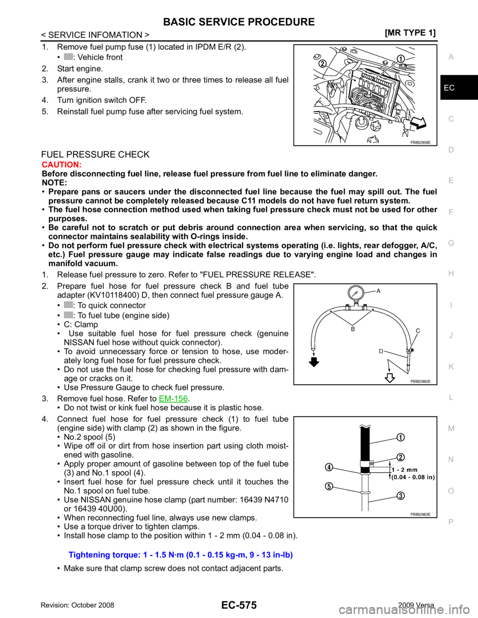
2. Prepare fuel hose for fuel pressure check B and fuel tube adapter (KV10118400) D, then connect fuel pressure gauge A.
• : To quick connector
• : To fuel tube (engine side)
• C: Clamp
• Use suitable fuel hose for fuel pressure check (genuine
NISSAN fuel hose without quick connector).
• To avoid unnecessary force or tension to hose, use moder- ately long fuel hose for fuel pressure check.
• Do not use the fuel hose for checking fuel pressure with dam- age or cracks on it.
• Use Pressure Gauge to check fuel pressure.
3. Remove fuel hose. Refer to EM-156 .
• Do not twist or kink fuel hose because it is plastic hose.
4. Connect fuel hose for fuel pressure check (1) to fuel tube (engine side) with clamp (2) as shown in the figure.
• No.2 spool (5)
• Wipe off oil or dirt from hose insertion part using cloth moist-
ened with gasoline.
• Apply proper amount of gasoline between top of the fuel tube (3) and No.1 spool (4).
• Insert fuel hose for fuel pressure check until it touches the No.1 spool on fuel tube.
• Use NISSAN genuine hose clamp (part number: 16439 N4710
or 16439 40U00).
• When reconnecting fuel line, always use new clamps.
• Use a torque driver to tighten clamps.
• Install hose clamp to the positi on within 1 - 2 mm (0.04 - 0.08 in).
• Make sure that clamp screw does not contact adjacent parts.
Page 2380 of 4331
![NISSAN LATIO 2009 Service Repair Manual EC-1024< SERVICE INFOMATION >
[MR TYPE 2]
PRECAUTIONS
• Do not operate fuel pump when there is no fuel in lines.
• Tighten fuel hose clamps to the specified torque.
- Fuel level sensor unit and NISSAN LATIO 2009 Service Repair Manual EC-1024< SERVICE INFOMATION >
[MR TYPE 2]
PRECAUTIONS
• Do not operate fuel pump when there is no fuel in lines.
• Tighten fuel hose clamps to the specified torque.
- Fuel level sensor unit and](/manual-img/5/57359/w960_57359-2379.png)
EC-1024< SERVICE INFOMATION >
[MR TYPE 2]
PRECAUTIONS
• Do not operate fuel pump when there is no fuel in lines.
• Tighten fuel hose clamps to the specified torque.
- Fuel level sensor unit and fuel pump (1)
- Fuel pressure regulator (2)
- Fuel level sensor (3)
- Fuel tank temperature sensor (4)
• Do not depress accelerator pedal when starting.
• Immediately after starting, do not rev up engine unnecessar-
ily.
• Do not rev up engine just prior to shutdown.
• When installing C.B. ham radio or a mobile phone, be sure to
observe the following as it m ay adversely affect electronic
control systems depending on installation location.
- Keep the antenna as far as possi ble from the electronic con-
trol units.
- Keep the antenna feeder line more than 20 cm (8 in) away
from the harness of electronic controls.
Do not let them run parallel for a long distance.
- Adjust the antenna and feeder line so that the standing-wave
radio can be kept smaller.
- Be sure to ground the radio to vehicle body. BBIA0704E
SEF709Y
SEF708Y
Page 2443 of 4331
![NISSAN LATIO 2009 Service Repair Manual BASIC SERVICE PROCEDURE
EC-1087
< SERVICE INFOMATION >
[MR TYPE 2] C
D E
F
G H
I
J
K L
M A EC
NP
O
1. Remove fuel pump fuse (1) located in IPDM E/R (2).
• : Vehicle front
2. Start engine.
3. After e NISSAN LATIO 2009 Service Repair Manual BASIC SERVICE PROCEDURE
EC-1087
< SERVICE INFOMATION >
[MR TYPE 2] C
D E
F
G H
I
J
K L
M A EC
NP
O
1. Remove fuel pump fuse (1) located in IPDM E/R (2).
• : Vehicle front
2. Start engine.
3. After e](/manual-img/5/57359/w960_57359-2442.png)
BASIC SERVICE PROCEDURE
EC-1087
< SERVICE INFOMATION >
[MR TYPE 2] C
D E
F
G H
I
J
K L
M A EC
NP
O
1. Remove fuel pump fuse (1) located in IPDM E/R (2).
• : Vehicle front
2. Start engine.
3. After engine stalls, crank it two or three times to release all fuel pressure.
4. Turn ignition switch OFF.
5. Reinstall fuel pump fuse after servicing fuel system.
FUEL PRESSURE CHECK CAUTION:
Before disconnecting fuel line, release fuel pressure from fuel line to eliminate danger.
NOTE:
• Prepare pans or saucers under the disconnected fuel line because the fuel may spill out. The fuel
pressure cannot be completely released because C11 models do not have fuel return system.
• The fuel hose connection method u sed when taking fuel pressure check must not be used for other
purposes.
• Be careful not to scratch or put debris around connection area when servicing, so that the quick
connector maintains seal abil ity with O-rings inside.
• Do not perform fuel pressure check with electrical syst ems operating (i.e. lights, rear defogger, A/C,
etc.) Fuel pressure gauge may indicate false readin gs due to varying engine load and changes in
manifold vacuum.
1. Release fuel pressure to zero. Refer to "FUEL PRESSURE RELEASE".
2. Prepare fuel hose for fuel pressure check B and fuel tube adapter (KV10118400) D, then connect fuel pressure gauge A.
• : To quick connector
• : To fuel tube (engine side)
• C: Clamp
• Use suitable fuel hose for fuel pressure check (genuine
NISSAN fuel hose without quick connector).
• To avoid unnecessary force or tension to hose, use moder- ately long fuel hose for fuel pressure check.
• Do not use the fuel hose for checking fuel pressure with dam- age or cracks on it.
• Use Pressure Gauge to check fuel pressure.
3. Remove fuel hose. Refer to EM-156, " Removal and Installation " .
• Do not twist or kink fuel hose because it is plastic hose.
4. Connect fuel hose for fuel pressure check (1) to fuel tube (engine side) with clamp (2) as shown in the figure.
• No.2 spool (5)
• Wipe off oil or dirt from hose insertion part using cloth moist-
ened with gasoline.
• Apply proper amount of gasoline between top of the fuel tube (3) and No.1 spool (4).
• Insert fuel hose for fuel pressure check until it touches the No.1 spool on fuel tube.
• Use NISSAN genuine hose clamp (part number: 16439 N4710
or 16439 40U00).
• When reconnecting fuel line, always use new clamps.
• Use a torque driver to tighten clamps.
• Install hose clamp to the positi on within 1 - 2 mm (0.04 - 0.08 in).
• Make sure that clamp screw does not contact adjacent parts. PBIB2958E
Tightening torque: 1 - 1.5 N·m
(0.1 - 0.15 kg-m, 9 - 13 in-lb) PBIB2982E
PBIB2983E