Page 1713 of 1903
Downloaded from www.Manualslib.com manuals search engine 4.CHECK IMMOBILIZER CONTROL MODULE POWER SUPPLY
• Turn ignition switch on.
• Check if voltage is present on the Immobilizer control module connector C-025, pin 4,1 and ground.
IMMOBILIZER CONTROL
MODULE TERMINAL GROUND
1
Ground
4
Is 12 V present?
Ye s>>Replace and program the Immobilizer control module. Refer to DTC B3077 Diagnostic Procedure.
No
>>For DTC B3050, go to the next step.
For DTC B3053, go to the step 6.
5.CHECK IMMOBILIZER CONTROL MODULE POWER SUPPLY CIRCUIT
• Turn ignition switch off.
• Disconnect the negative battery cable.
• Disconnect the body fuse and relay box electrical connector A.
• Check harness continuity between the following terminals:
• Continuity should exist.
BODY FUSE
AND RELAY BOX
TERMINAL IMMOBILIZER
CONTROLMODULE
TERMINAL CONTINUITY
A2
1Yes
DIAGNOSIS & TESTING
15
15–129Chery Automobile Co., Ltd.
Page 1714 of 1903

Downloaded from www.Manualslib.com manuals search engine •Check for harness continuity between the following terminals:
• Continuity should exist.
BODY FUSE
AND RELAY BOX
TERMINAL IMMOBILIZER
CONTROLMODULE
TERMINAL CONTINUITY
A6
4Yes
• Check harness for a short to ground.
• Continuity between Immobilizer control module power supply and ground should not exist.
Is the check result normal?
Ye s>>Go to the step 7.
No
>>Repair or replace the open or high resistance circuit or short to ground in harness or connectors.
6.CHECK IMMOBILIZER CONTROL MODULE POWER SUPPLY CIRCUIT
• Turn ignition switch off.
• Disconnect the negative battery cable.
• Disconnect the body fuse and relay box electrical connector A.
• Check the resistance between Immobilizer control module ignition switch circuit terminal 4 and Immobilizer con-
trol module battery supply circuit terminal 1.
IMMOBILIZER
CONTROLMODULE
TERMINAL IMMOBILIZER
CONTROLMODULE
TERMINAL CONTINUITY
14N
o
• Check resistance between Immobilizer control module ignition switch circuit and other power circuits.
Is the check result normal?
Ye s>>Go to the step 8.
No
>>Repair or replace short to power circuits in harness or connectors.
DIAGNOSIS & TESTING
15–130Chery Automobile Co., Ltd.
Page 1715 of 1903
Downloaded from www.Manualslib.com manuals search engine 7.DETECT MALFUNCTIONING PART
• Check the following:
� Body fuse and relay box
� Fuse F17 (10A), fuse F26 (10A)
� Harness between battery and body fuse and relay box
Is the check result normal?
Ye s>>Go to the next step.
No
>>Repair or replace damaged components.
8.REPLACE AND PROGRAM THE IMMOBILIZER CONTROL MODULE
• With the X-431 scan tool, view active DTCs in the Immobilizer control module.
• Refer to �DTC Confirmation Procedure�.
Is DTC B3050 or B3053 still present?
Ye s>>Replace and program Immobilizer control module.
No
>>The system is now operating properly.
Reassemble the vehicle and verify the customers complaint is repaired.
DIAGNOSIS & TESTING
15
15–131Chery Automobile Co., Ltd.
Page 1716 of 1903
Downloaded from www.Manualslib.com manuals search engine B3055 - No Transponder Modulation Or No Transponder
B3056 - No Transponder Fixed Code Programmed
DIAGNOSIS & TESTING
LTSMW150081T
15–132Chery Automobile Co., Ltd.
Page 1717 of 1903

Downloaded from www.Manualslib.com manuals search engine On Board Diagnostic Logic
•Self-diagnosis detection logic.
DTC NO. DTC DEFINITION DTC DETECTION
CONDITION DTC SET
CONDITION POSSIBLE CAUSE
B3055 No transponder
modulation or no transponder Ignition switch: ON The Immobilizer
control module
detects no
transponder or no
transponder
modulation
condition. •
Transponder
• Harness or
connectors
• Immobilizer control
module
B3056 No transponder
fixed code
programmed Ignition switch: ON The Immobilizer
control module
detects that the
transponder is not
programmed. •
Transponder
• Harness or
connectors
• Immobilizer control
module
DTC Confirmation Procedure:
Before performing the following procedure, confirm that battery voltage is more than 12 V.
• Turn ignition switch off.
• Connect the X-431 scan tool to the Data Link Connector (DLC) - use the most current software available.
• Turn the ignition switch on, with the scan tool, view and erase stored DTCs in the Immobilizer control module.
• Try to start the engine.
• Turn ignition switch off, and wait a few seconds, then turn the ignition switch on.
• With the scan tool, view active DTCs in the Immobilizer control module.
• If the DTC is detected, the condition is current. Go to Diagnostic Procedure - Step 1.
• If the DTC is not detected, the DTC condition is intermittent (See Diagnostic Help and Intermittent DTC Trou-
bleshooting in Section 15 Body & Accessories for more information).
NOTE :
While performing electrical diagnosis & testing, always refer to the electrical schematics for specific circuit
and component information.
Diagnostic Procedure
1.CHECK GROUND CONNECTION
• Turn ignition switch off.
• Loosen and retighten ground screws on the body (See Ground Inspection in Section 15 Body & Accessories).
• Inspect ground connection C-204 mounting position (See Vehicle Wiring Harness Layout - Main Harness in
Section 16 Wiring).
Is the ground connection OK?
Ye s>>Go to the next step.
No
>>Repair or replace ground connection.
2.CHECK IMMOBILIZER CONTROL MODULE DTC
• With the scan tool, view DTCs in the Immobilizer control module. Refer to DTC confirmation procedure.
Is DTC B3055 present?
Ye s>>Go to the next step.
No
>>The condition that caused the DTC to set is currently not present (See Diagnosis & Testing Diagnostic
Help in Section 15 Body & Accessories).
DIAGNOSIS & TESTING
15
15–133Chery Automobile Co., Ltd.
Page 1718 of 1903
Downloaded from www.Manualslib.com manuals search engine 3.CHECK IMMOBILIZER CONTROL MODULE ELECTRICAL CONNECTOR
• Turn ignition switch off.
• Disconnect the Immobilizer control module electrical
connectors C-026 (1).
• Inspect the electrical connector for damage.
Is the electrical connector OK?
Ye s>>Go to the next step.
No
>>Repair or replace the electrical connector
as necessary.
4.CHECK IMMOBILIZER COIL
• Check the resistance of the Immobilizer coil between the Immobilizer coil connector C-026, pin 9 and pin 11.
IMMOBILIZER COIL
TERMINAL IMMOBILIZER COIL
TERMINAL
91 1
Is the resistance range from 5 to 20 ohms?
Ye s>>Go to the next step.
No
>>Replace the Immobilizer coil.
DIAGNOSIS & TESTING
LTSMD150019
15–134Chery Automobile Co., Ltd.
Page 1719 of 1903
Downloaded from www.Manualslib.com manuals search engine 5.CHECK IMMOBILIZER COIL
• Check the resistance of the Immobilizer coil between the Immobilizer coil connector C-026, pin 9 and pin 10.
• Check the resistance of the Immobilizer coil between the Immobilizer coil connector C-026, pin 11 and pin 10.
IMMOBILIZER
COIL
TERMINAL IMMOBILIZER
COIL
TERMINAL CONTINUITY
91
0
Not
11 1 0
• Continuity should not exist.
Is the check result normal?
Ye s>>Go to the next step.
No
>>Replace the Immobilizer coil.
6.REPLACE AND PROGRAM TRANSPONDER
• Reconnect the Immobilizer control module electrical
connector C-026.
• Replace the chip (1) with a new one.
DIAGNOSIS & TESTING
VISMD150018
15
15–135Chery Automobile Co., Ltd.
Page 1720 of 1903
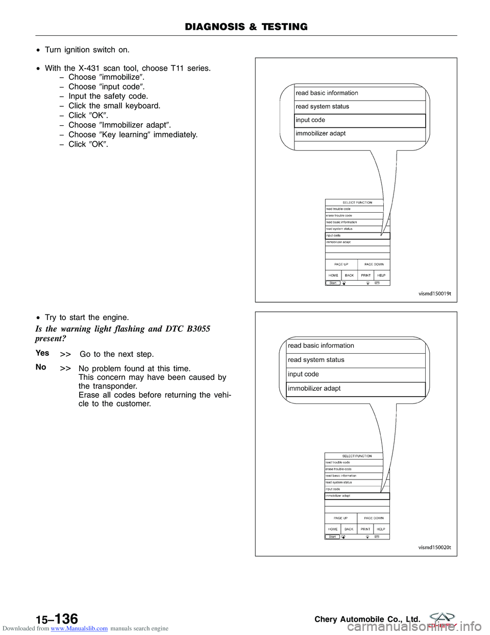
Downloaded from www.Manualslib.com manuals search engine •Turn ignition switch on.
• With the X-431 scan tool, choose T11 series.
� Choose �immobilize�.
� Choose �input code�.
� Input the safety code.
� Click the small keyboard.
� Click �OK�.
� Choose �Immobilizer adapt�.
� Choose �Key learning� immediately.
� Click �OK�.
• Try to start the engine.
Is the warning light flashing and DTC B3055
present?
Ye s>>Go to the next step.
No
>>No problem found at this time.
This concern may have been caused by
the transponder.
Erase all codes before returning the vehi-
cle to the customer.
DIAGNOSIS & TESTING
VISMD150019T
VISMD150020T
15–136Chery Automobile Co., Ltd.

, fuse F26 (10A)
� Harness between battery and")