Page 27 of 1903
Downloaded from www.Manualslib.com manuals search engine SERVICE MANUAL CHAPTERCOMPONENT / VEHICLE SYSTEM
08 - Transaxle & Transfer Case •
Transaxle Control Module (TCM)
• Automatic Transaxle Shifter Selector
• Automatic Transaxle Assembly
• Manual Transaxle Assembly
• Winter Mode Switch
• EPDE Solenoid Valve
• Backup Lamp Switch
• Integrated Torque Management (ITM) Control Module
09 - Driveline & Axle •None
10 - Suspension •None
11 - Steering •Power Steering Switch
12 - Brakes •
Antilock Brake System (ABS) Module
• Wheel Speed Sensors
• Brake Switch
• Parking Brake Switch
• Brake Fluid Level Switch
13 - Heating & Air Conditioning •
Manual Temperature Control System
• Blower Motor
• A/C Compressor
• Refrigerant Pressure Switch
14 - Restraints •
Restraints Control Module
• Seat Belt Buckle Switch
• Front Crash Sensors
• Driver Airbag
• Passenger Airbag
HOW TO LOCATE ELECTRICAL SCHEMATICS IN THE SERVICE MANUAL
01–26Chery Automobile Co., Ltd.
Page 28 of 1903

Downloaded from www.Manualslib.com manuals search engine SERVICE MANUAL CHAPTERCOMPONENT / VEHICLE SYSTEM
15 - Body & Accessories •
Windshield Wiper Motor
• Windshield Washer Motor
• Rear Window Defroster
• Power Door Locks
• Power Windows
• Power Mirrors
• Sunroof Control Unit
• Radio
• Interior Lights
• Exterior Lights
• Oil Pressure Switch
• Warning Buzzer
• Body Control Module (BCM)
• Instrument Cluster
• Key Switch
• Power Outlet
• Data Link Connector
• Immobilizer Control Module
• Horn
16 - Wiring •
Power Distribution
• Front Fuse and Relay Box
• Power Fuse Box
• Ignition Switch
• Ground Distribution
Abbreviation List
TERM ABBREVIATION
Antilock Brake System ABS
Accelerator Sensor AES
Accelerator Pedal Position Sensor APS
Automatic Temperature Control ATC
Automatic Transaxle Fluid ATF
Body Control Module BCM
Brake Pressure Sensor BPS
Camshaft Position Sensor CMP
Clutch Pedal Position Switch CPP Switch
Crankshaft Position Sensor CKP
Data Link Connector DLC
Diagnostic Trouble Code DTC
Engine Control Module ECM
Engine Coolant Temperature ECT
Engine Speed RPM
Evaporative Emission EVAP
Evaporative Emission Canister EVAP Canister
Evaporative Emission System EVAP System
Exhaust Gas Recirculation Valve EGR Valve
HOW TO LOCATE ELECTRICAL SCHEMATICS IN THE SERVICE MANUAL
01
01–27Chery Automobile Co., Ltd.
Page 948 of 1903
Downloaded from www.Manualslib.com manuals search engine DP0 Transaxle Internal View
1 - Torque Converter
2 - Fluid Pump Assembly
3 - Input Shaft
4 - Secondary Differential Driven Gear
5 - Differential Ring Gear
6 - Differential Case
7 - Parking Gear
8 - Primary Differential Driven Gear
9 - Transfer Shaft
10 - Brake F3 (1st and 2nd Gear)
11 - Brake F2 (Reverse Gear)12 - Brake F1 (4th Gear)
13 - Fluid Line
14 - Clutch E2 (2nd, 3rd and 4th Gear)
15 - Clutch E1 (Reverse and 1st Gear)
16 - Accumulator
17 - Manual Valve
18 - Accumulator
19 - Ratchet Gear Plate
20 - Accumulator Cover
21 - Planet Gear
22 - Primary Differential Drive Gear
GENERAL INFORMATION
BESM080056
08
08–5Chery Automobile Co., Ltd.
Page 961 of 1903

Downloaded from www.Manualslib.com manuals search engine DP0 Transaxle Control Module (TCM) Connector Pin-Out Table
TCM Pin-Out Table
PINCIRCUIT IDENTIFICATION PINCIRCUIT IDENTIFICATION
1 + EVS 29-
2 Flow Control Solenoid Valve (+) 30-
3 -31Shift 2
4 -32Shift 3
5 -33Shift 4
6 -34P/N Switch
7 Shift Solenoid Valve 3 35-
8 Shift Solenoid Valve 4 36Sequential (-)
9 Shift Solenoid Valve 2 37Sequential (+)
10 Shift Solenoid Valve 1 38CAN-H
11 Shift Lock 39CAN-L
12 Fluid Cooler Flow Control 40Winter Mode
13 Shift Solenoid Valve 5 41-
14 Shift Solenoid Valve 6 42MFS Switch
15 -43Brake Switch
16 Brake Switch 44-
17 -45Turbine Shaft (+)
18 -46Turbine Shaft (-)
19 CDE EVM PTG 47Secondary Shaft (-)
20 Torque Converter Lock Solenoid Valve
(CDE EVM PRSN) 48
Secondary Shaft (+)
21 -49 -
22 -50 -
23 -51 -
24 Regulated Sensor Supply 52-
25 Sensor (GND) 53Fluid Temperature Sensor (-)
26 Pressure Adjust Solenoid Valve (+EVM) 54 Fluid Temperature Sensor (+)
27 Ignition Switch 55Fluid Pressure Sensor
28 GND 56BATT
GENERAL INFORMATION
08–18Chery Automobile Co., Ltd.
Page 997 of 1903

Downloaded from www.Manualslib.com manuals search engine 4.COMPRESSED AIR TEST
• Check low speed clutch system: Low speed clutch piston should be active and maintain pressure when com-
pressed air is applied to the fluid hole.
• Check reverse/low brake clutch system: Low speed clutch piston should be active and maintain pressure when
compressed air is applied to the fluid hole.
Is the check result normal?
Ye s>>Go to the next step for disc or plate abrasion.
No
>>Replace the damaged components as needed.
5.CHECK CLUTCH SYSTEM
• Check low speed clutch system:
� 2, 3, 4 gear clutch (E2)
� Reverse and1-3gear clutch (E1)
� Check clutch plate
� Check clutch disc
� Snap ring
� Clutch reaction disc
� D-Ring
� Spring retainer
Is the check result normal?
Ye s>>Go to the next step.
No
>>Replace the damaged components.
6.CHECK BRAKE SYSTEM
• Check reverse/low brake system:
� 4 gear brake (F1)
� Reverse gear brake (F2)
� 1, 2 gear brake (F3)
� Check brake plate
� Check brake disc
� Central support
� Snap ring
� Spring retainer
� Brake piston
Is the check result normal?
Ye s>>Go to the next step.
No
>>Replace the damaged components.
DIAGNOSIS & TESTING
08–54Chery Automobile Co., Ltd.
Page 1083 of 1903
Downloaded from www.Manualslib.com manuals search engine WARNING!
The gearshift lever must be shifted to gear P while adding transaxle fluid.
Automatic Shifter Selector
Removal & Installation
1. Raise and support the vehicle.
2. Disconnect the negative battery cable.
3. Remove the air cleaner and air duct transaxle assembly.
4. Remove the base mounting (1) of the air cleanertransaxle assembly.
5. Depress the clip then remove the shift cable (1) from the transaxle gearshift switch and remove the
shift cable clamp (2).
6. Remove the gearshift knob (1).
7. Remove the gearshift cover (2) from the lower console.
8. Apply the parking brake (apply the parking brake handle to clear lower console during removal).
9. Remove the lower console (See Lower Console Removal & Installation in Section 15 Body & Accessories).
ON-VEHICLE SERVICE
BESM080038
LTSM080186
BESM080049
08–140Chery Automobile Co., Ltd.
Page 1087 of 1903

Downloaded from www.Manualslib.com manuals search engine GENERAL INFORMATION
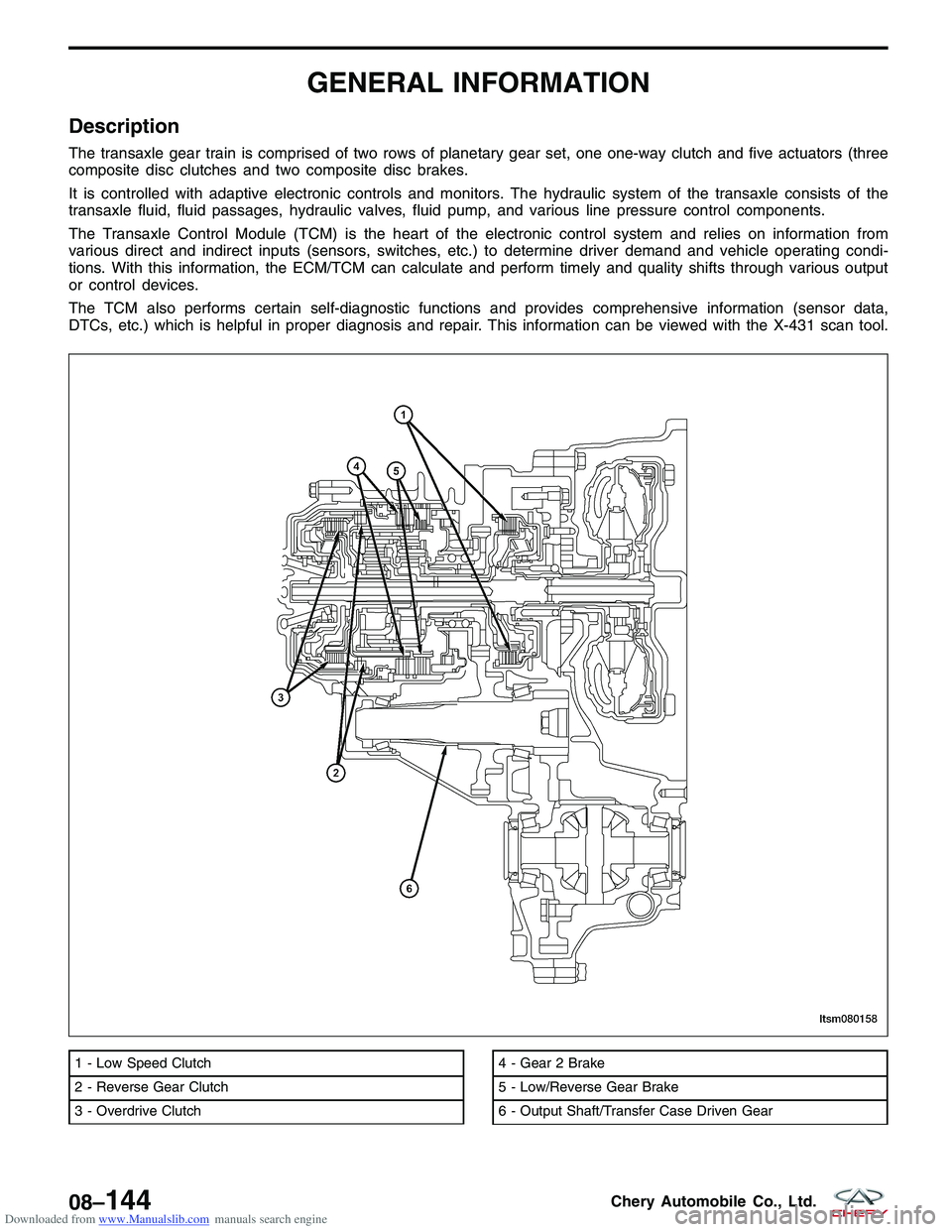
Description
The transaxle gear train is comprised of two rows of planetary gear set, one one-way clutch and five actuators (three
composite disc clutches and two composite disc brakes.
It is controlled with adaptive electronic controls and monitors. The hydraulic system of the transaxle consists of the
transaxle fluid, fluid passages, hydraulic valves, fluid pump, and various line pressure control components.
The Transaxle Control Module (TCM) is the heart of the electronic control system and relies on information from
various direct and indirect inputs (sensors, switches, etc.) to determine driver demand and vehicle operating condi-
tions. With this information, the ECM/TCM can calculate and perform timely and quality shifts through various output
or control devices.
The TCM also performs certain self-diagnostic functions and provides comprehensive information (sensor data,
DTCs, etc.) which is helpful in proper diagnosis and repair. This information can be viewed with the X-431 scan tool.
1 - Low Speed Clutch
2 - Reverse Gear Clutch
3 - Overdrive Clutch4 - Gear 2 Brake
5 - Low/Reverse Gear Brake
6 - Output Shaft/Transfer Case Driven Gear
LTSM080158
08–144Chery Automobile Co., Ltd.
Page 1090 of 1903

Downloaded from www.Manualslib.com manuals search engine Specifications
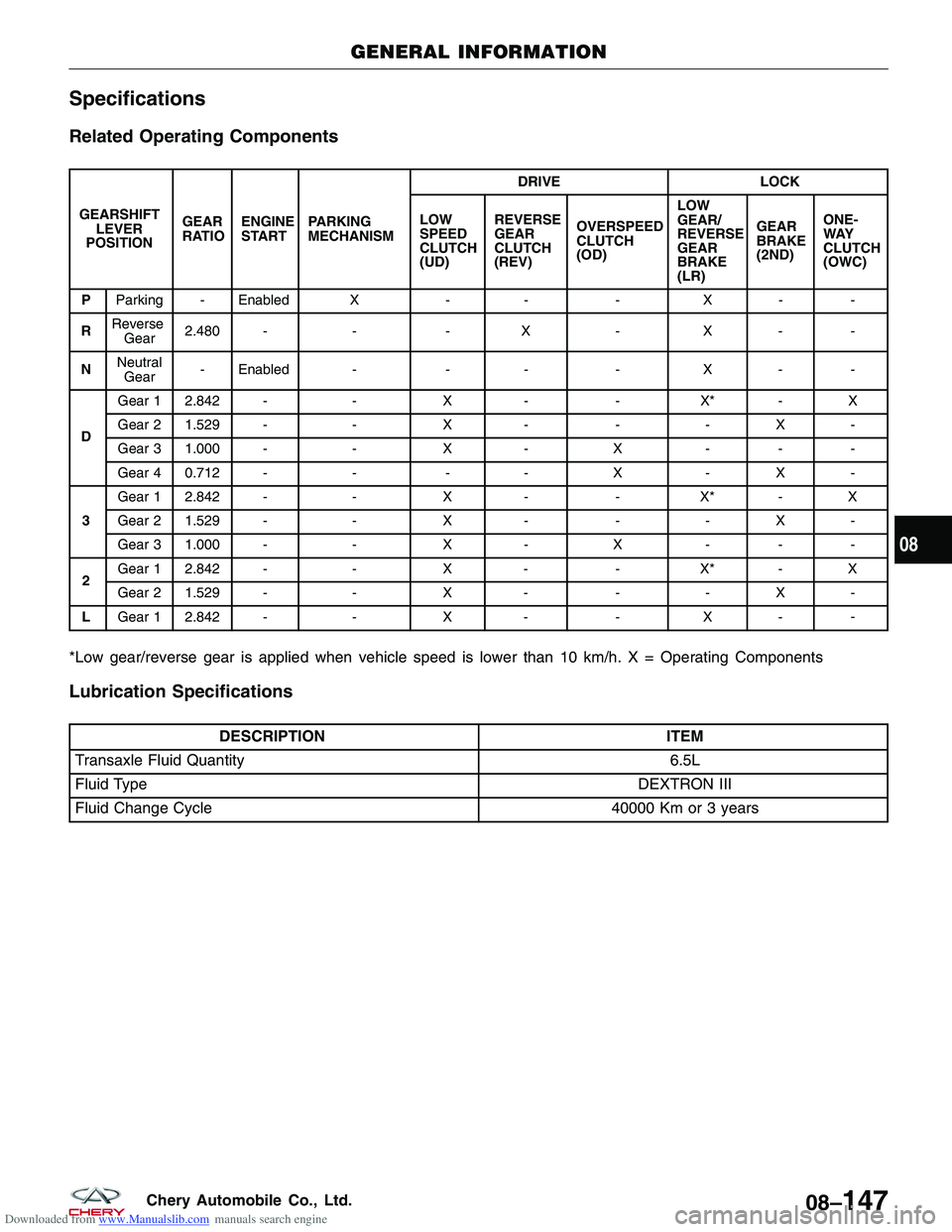
Related Operating Components
GEARSHIFTLEVER
POSITION GEAR
RATIO
ENGINE
START PARKING
MECHANISM DRIVE
LOCK
LOW
SPEED
CLUTCH
(UD) REVERSE
GEAR
CLUTCH
(REV)
OVERSPEED
CLUTCH
(OD) LOW
GEAR/
REVERSE
GEAR
BRAKE
(LR)GEAR
BRAKE
(2ND)
ONE-
WAY
CLUTCH
(OWC)
P Parking - Enabled X -- -X - -
R Reverse
Gear 2.480 -
--X -X - -
N Neutral
Gear - Enabled -
-- -X - -
D Gear 1 2.842 -
-X- -X* - X
Gear 2 1.529 - -X- -- X -
Gear 3 1.000 - -X- X - - -
Gear 4 0.712 - --- X - X -
3 Gear 1 2.842 -
-X- -X* - X
Gear 2 1.529 - -X- -- X -
Gear 3 1.000 - -X- X - - -
2 Gear 1 2.842 -
-X- -X* - X
Gear 2 1.529 - -X- -- X -
L Gear 1 2.842 - -X- -X - -
*Low gear/reverse gear is applied when vehicle speed is lower than 10 km/h. X = Operating Components
Lubrication Specifications
DESCRIPTION
ITEM
Transaxle Fluid Quantity 6.5L
Fluid Type DEXTRON III
Fluid Change Cycle 40000 Km or 3 years
GENERAL INFORMATION
08
08–147Chery Automobile Co., Ltd.