Page 27 of 1903
Downloaded from www.Manualslib.com manuals search engine SERVICE MANUAL CHAPTERCOMPONENT / VEHICLE SYSTEM
08 - Transaxle & Transfer Case •
Transaxle Control Module (TCM)
• Automatic Transaxle Shifter Selector
• Automatic Transaxle Assembly
• Manual Transaxle Assembly
• Winter Mode Switch
• EPDE Solenoid Valve
• Backup Lamp Switch
• Integrated Torque Management (ITM) Control Module
09 - Driveline & Axle •None
10 - Suspension •None
11 - Steering •Power Steering Switch
12 - Brakes •
Antilock Brake System (ABS) Module
• Wheel Speed Sensors
• Brake Switch
• Parking Brake Switch
• Brake Fluid Level Switch
13 - Heating & Air Conditioning •
Manual Temperature Control System
• Blower Motor
• A/C Compressor
• Refrigerant Pressure Switch
14 - Restraints •
Restraints Control Module
• Seat Belt Buckle Switch
• Front Crash Sensors
• Driver Airbag
• Passenger Airbag
HOW TO LOCATE ELECTRICAL SCHEMATICS IN THE SERVICE MANUAL
01–26Chery Automobile Co., Ltd.
Page 63 of 1903

Downloaded from www.Manualslib.com manuals search engine 20. If equipped with an automatic transaxle, removethe transaxle shift cable (1) and the transaxle shift
cable clamp (2).
21. Remove the hydraulic pipe from the clutch slave cylinder.
22. Remove the A/C compressor line bolt (1) from the A/C compressor.
(Tighten: A/C compressor line bolts to 20 N·m)
NOTE: After removing the A/C lines, plug the A/C
lines to prevent any debris from entering the A/C
system.
23. Remove the high pressure line (1) and low pres- sure line (2) from the power steering pump (drain
fluid from lines).
(Tighten: High pressure line to power steering
pump 40 ± 5 N·m)
(Tighten: Low pressure line to power steering pump
40 ± 5 N·m)
24. Remove the exhaust manifold heat shield bolts (1) and then remove heat shield.
(Tighten: Exhaust manifold heat shield bolts to 15
N·m)
25. Disconnect the upstream and downstream oxygen sensor connectors.
ON-VEHICLE SERVICE
LTSM080186
VISM130017
BESM110011
BESM020078
02–34Chery Automobile Co., Ltd.
Page 137 of 1903
Downloaded from www.Manualslib.com manuals search engine 20. If equipped with an automatic transaxle remove thetransaxle shift cable (1) and the shift cable clamp
(2).
21. Remove the A/C compressor line bolt (1) from the A/C compressor.
(Tighten: A/C compressor line bolts to 20 N·m)
NOTE :
After removing the A/C lines, plug the A/C lines to pre-
vent any debris from entering the A/C system.
22. Remove the high pressure line (1) and low pres- sure line (2) from the power steering pump (drain
fluid from lines).
(Tighten: High pressure line to power steering
pump 40 ± 5 N·m)
(Tighten: Low pressure line to power steering pump
40 ± 5 N·m)
23. Remove the exhaust manifold heat shield bolts (1) and then remove heat shield.
(Tighten: Exhaust manifold heat shield bolts to 15
N·m)
24. Disconnect the upstream and downstream oxygen sensor connectors.
ON-VEHICLE SERVICE
LTSM080186
VISM130017
BESM110011
BESM020078
02
02–108Chery Automobile Co., Ltd.
Page 215 of 1903
Downloaded from www.Manualslib.com manuals search engine 21. Disconnect the following automatic transaxle elec-trical connectors:• Output shaft sensor (1)
• Input shaft sensor (2)
• Electromagnetic valve switch connector (3)
• Gear switch connector (5)
22. Disconnect the transaxle fluid lines (6) using a suit- able tool.
23. Remove the shift cable (4) from the transaxle assembly.
24. Remove the catalytic converter to exhaust manifold bolts (1).
(Tighten: Exhaust manifold bolt to 49 ± 5 N·m)
25. Remove the front axle shaft (See Front Axle Shaft Removal & Installation in Section 09 Driveline & Axle).
26. Raise and support the vehicle.
27. Drain the engine oil.
28. Remove the power steering pump fluid line and set aside (See Power steering pump Removal & Installation in Section 11 Steering).
29. Lower the vehicle and install engine lift chain hangers.
ON-VEHICLE SERVICE
LTSM080153
LTSM020189
02–186Chery Automobile Co., Ltd.
Page 1307 of 1903
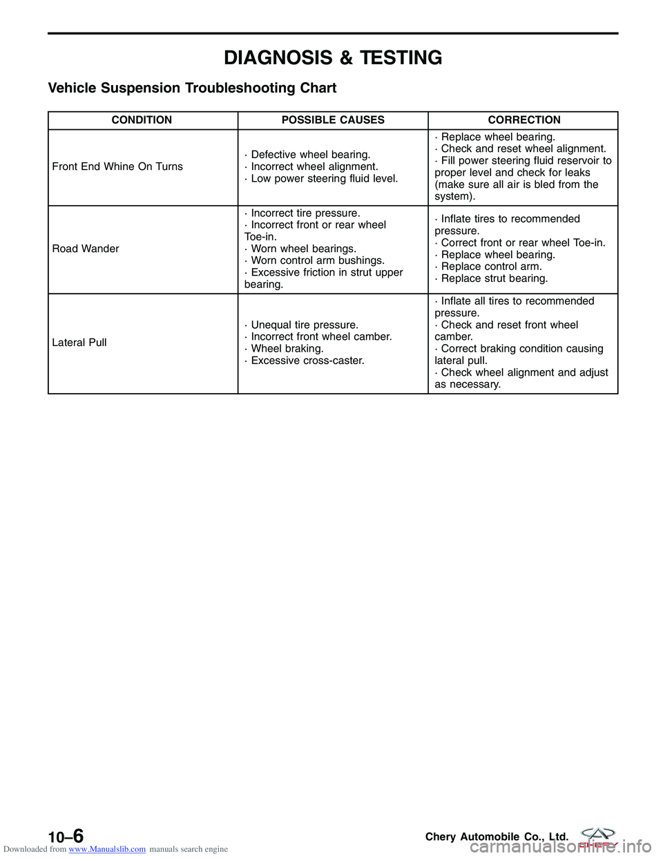
Downloaded from www.Manualslib.com manuals search engine DIAGNOSIS & TESTING
Vehicle Suspension Troubleshooting Chart
CONDITIONPOSSIBLE CAUSES CORRECTION
Front End Whine On Turns · Defective wheel bearing.
· Incorrect wheel alignment.
· Low power steering fluid level.· Replace wheel bearing.
· Check and reset wheel alignment.
· Fill power steering fluid reservoir to
proper level and check for leaks
(make sure all air is bled from the
system).
Road Wander · Incorrect tire pressure.
· Incorrect front or rear wheel
Toe-in.
· Worn wheel bearings.
· Worn control arm bushings.
· Excessive friction in strut upper
bearing.· Inflate tires to recommended
pressure.
· Correct front or rear wheel Toe-in.
· Replace wheel bearing.
· Replace control arm.
· Replace strut bearing.
Lateral Pull · Unequal tire pressure.
· Incorrect front wheel camber.
· Wheel braking.
· Excessive cross-caster.· Inflate all tires to recommended
pressure.
· Check and reset front wheel
camber.
· Correct braking condition causing
lateral pull.
· Check wheel alignment and adjust
as necessary.
10–6Chery Automobile Co., Ltd.
Page 1320 of 1903
Downloaded from www.Manualslib.com manuals search engine 12. Remove the exhaust pipe assembly (See Exhaust Pipe Removal & Installation in Section 07 Exhaust).
13. Remove the high pressure and low pressure lines(1) from the steering gear (drain steering fluid from
lines).
(Tighten: High pressure line to power steering
pump 27 - 33 N·m)
(Tighten: Low pressure line to power steering pump
27 - 33 N·m)
14. Remove the two bolts (1) between the steering gearing and the sub-frame.
(Tighten: Steering gear to sub-frame bolts to 70 -
80 N·m)
ON-VEHICLE SERVICE
LTSM110007
LTSM100024
10
10–19Chery Automobile Co., Ltd.
Page 1356 of 1903
Downloaded from www.Manualslib.com manuals search engine STEERING
11
CONTENTSpage
Steering System ..................................................................... 11-1
Steering Column ..................................................................... 11-8
Steering Gear ...................................................................... 11-18
Power Steering Pump ................................................................ 11-31
STEERING SYSTEM
GENERAL INFORMATION11-2
Description 11-2
Operation 11-2
Specifications 11-3
Special Tools 11-3
DIAGNOSIS & TESTING11-4
Power Steering Troubleshooting Chart 11-4
Power Steering Fluid Troubleshooting
Chart 11-5
ON-VEHICLE SERVICE11-6
Power Steering Filling and Flushing 11-6
Filling 11-6
Flushing 11-6
Inspection 11-7
11
11 –1Chery Automobile Co., Ltd.
Page 1357 of 1903
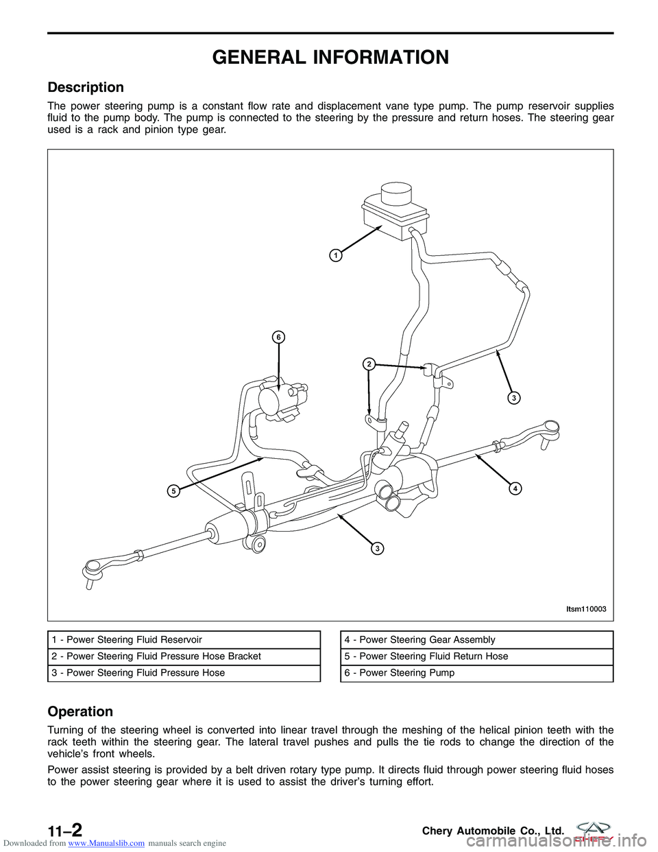
Downloaded from www.Manualslib.com manuals search engine GENERAL INFORMATION
Description
The power steering pump is a constant flow rate and displacement vane type pump. The pump reservoir supplies
fluid to the pump body. The pump is connected to the steering by the pressure and return hoses. The steering gear
used is a rack and pinion type gear.
Operation
Turning of the steering wheel is converted into linear travel through the meshing of the helical pinion teeth with the
rack teeth within the steering gear. The lateral travel pushes and pulls the tie rods to change the direction of the
vehicle’s front wheels.
Power assist steering is provided by a belt driven rotary type pump. It directs fluid through power steering fluid hoses
to the power steering gear where it is used to assist the driver’s turning effort.
1 - Power Steering Fluid Reservoir
2 - Power Steering Fluid Pressure Hose Bracket
3 - Power Steering Fluid Pressure Hose4 - Power Steering Gear Assembly
5 - Power Steering Fluid Return Hose
6 - Power Steering Pump
LTSM110003
11 –2Chery Automobile Co., Ltd.


