2009 CHERY TIGGO wheel alignment
[x] Cancel search: wheel alignmentPage 1278 of 1903
Downloaded from www.Manualslib.com manuals search engine DIAGNOSIS & TESTING
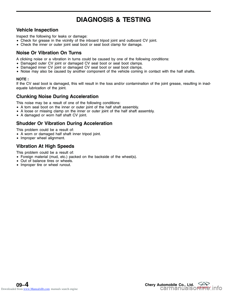
Vehicle Inspection
Inspect the following for leaks or damage:
•Check for grease in the vicinity of the inboard tripod joint and outboard CV joint.
• Check the inner or outer joint seal boot or seal boot clamp for damage.
Noise Or Vibration On Turns
A clicking noise or a vibration in turns could be caused by one of the following conditions:
•Damaged outer CV joint or damaged CV seal boot or seal boot clamps.
• Damaged inner CV joint or damaged CV seal boot or seal boot clamps.
• Noise may also be caused by another component of the vehicle coming in contact with the half shafts.
NOTE :
If the CV seal boot is damaged, this will result in the loss and/or contamination of the joint grease, resulting in inad-
equate lubrication of the joint.
Clunking Noise During Acceleration
This noise may be a result of one of the following conditions:
• A torn seal boot on the inner or outer joint of the half shaft assembly.
• A loose or missing clamp on the inner or outer joint of the half shaft assembly.
• A damaged or worn half shaft CV joint.
Shudder Or Vibration During Acceleration
This problem could be a result of:
•A worn or damaged half shaft inner tripod joint.
• Improper wheel alignment.
Vibration At High Speeds
This problem could be a result of:
•Foreign material (mud, etc.) packed on the backside of the wheel(s).
• Out of balance tires or wheels.
• Improper tire or wheel runout.
09–4Chery Automobile Co., Ltd.
Page 1285 of 1903

Downloaded from www.Manualslib.com manuals search engine DIAGNOSIS & TESTING
Vehicle Inspection
Inspect the rear axle for the following:
•Check the rear axle for loose bearings.
• Check the rear axle hub for any damage or excessive runout.
Shudder Or Vibration During Acceleration
This problem could be a result of:
•A worn or damaged half shaft inner tripod joint (4x4).
• Improper wheel alignment.
Vehicle Inspection
Inspect the following for leaks or damage:
•Check for grease in the vicinity of the inboard tripod joint and outboard CV joint (4x4).
• Check the inner or outer joint seal boot or seal boot clamp for damage (4x4).
Noise Or Vibration On Turns
A clicking noise or a vibration in turns could be caused by one of the following conditions:
•Damaged outer CV joint or damaged CV seal boot or seal boot clamps (4x4).
• Damaged inner CV joint or damaged CV seal boot or seal boot clamps (4x4).
• Noise may also be caused by another component of the vehicle coming in contact with the half shafts (4x4).
NOTE :
If the CV seal boot is damaged, this will result in the loss and/or contamination of the joint grease, resulting in inad-
equate lubrication of the joint.
Clunking Noise During Acceleration
This noise may be a result of one of the following conditions:
• A torn seal boot on the inner or outer joint of the half shaft assembly (4x4).
• A loose or missing clamp on the inner or outer joint of the half shaft assembly (4x4).
• A damaged or worn half shaft CV joint (4x4).
Shudder Or Vibration During Acceleration
This problem could be a result of:
•A worn or damaged half shaft inner tripod joint (4x4).
• Improper wheel alignment.
Vibration At High Speeds
This problem could be a result of:
•Foreign material (mud, etc.) packed on the backside of the wheel(s).
• Out of balance tires or wheels.
• Improper tire or wheel runout.
Visual Inspection For Fluid Leaks (4x4)
This problem could be a result of:
•Where seals are used: There should be no appearance of fluid leakage or abnormal abrasions.
• Where sealant is applied: There should be no appearance of fluid leakage or fluid seepage.
• Where attaching bolts are used, fluid-fill and fluid-draining plugs are used: There should be no appearance of
fluid leakage, fluid seepage or loose bolts.
• The housing: There should be no appearance of fluid leakage or fluid seepage.
09
09–11Chery Automobile Co., Ltd.
Page 1300 of 1903
Downloaded from www.Manualslib.com manuals search engine DIAGNOSIS & TESTING
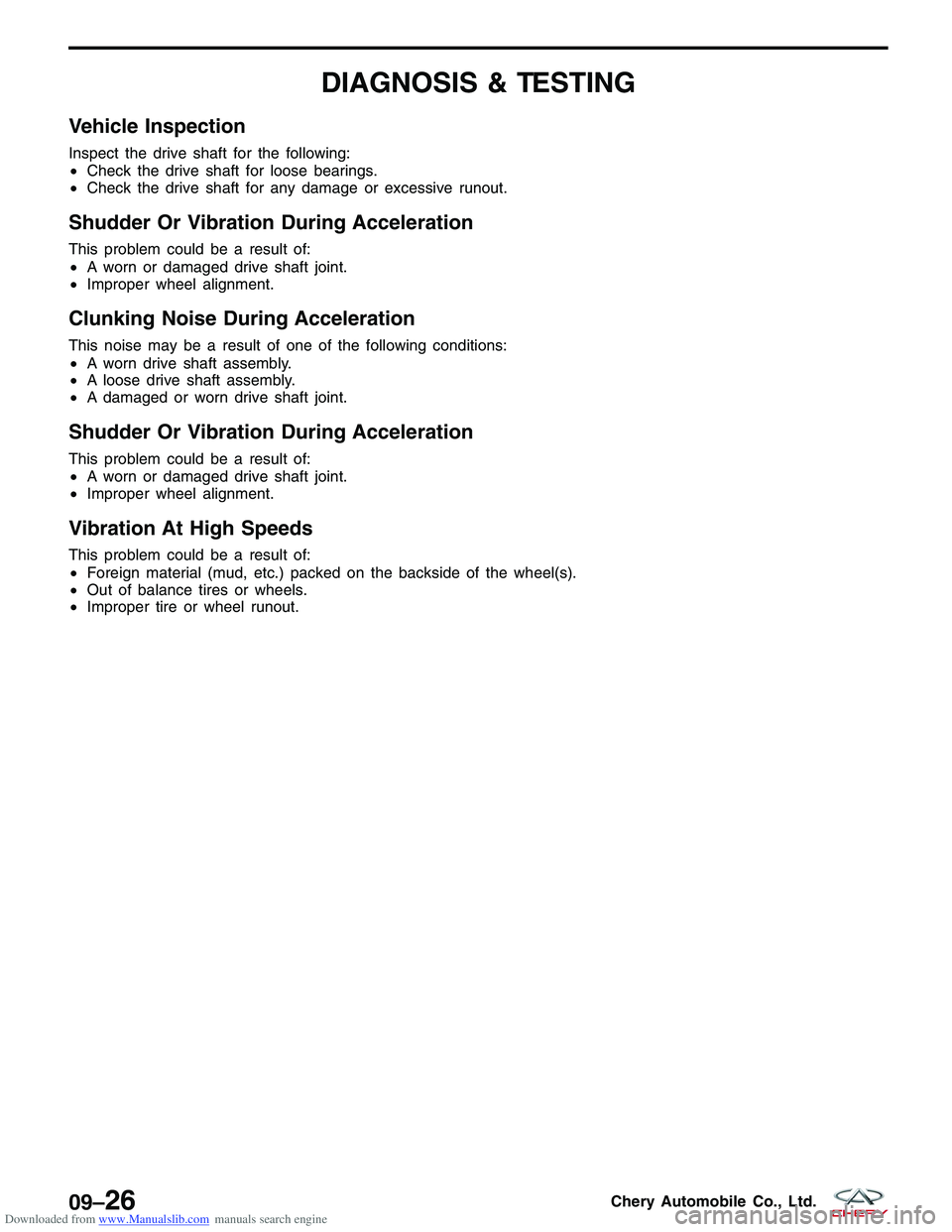
Vehicle Inspection
Inspect the drive shaft for the following:
•Check the drive shaft for loose bearings.
• Check the drive shaft for any damage or excessive runout.
Shudder Or Vibration During Acceleration
This problem could be a result of:
•A worn or damaged drive shaft joint.
• Improper wheel alignment.
Clunking Noise During Acceleration
This noise may be a result of one of the following conditions:
•A worn drive shaft assembly.
• A loose drive shaft assembly.
• A damaged or worn drive shaft joint.
Shudder Or Vibration During Acceleration
This problem could be a result of:
•A worn or damaged drive shaft joint.
• Improper wheel alignment.
Vibration At High Speeds
This problem could be a result of:
•Foreign material (mud, etc.) packed on the backside of the wheel(s).
• Out of balance tires or wheels.
• Improper tire or wheel runout.
09–26Chery Automobile Co., Ltd.
Page 1302 of 1903
Downloaded from www.Manualslib.com manuals search engine SUSPENSION
10
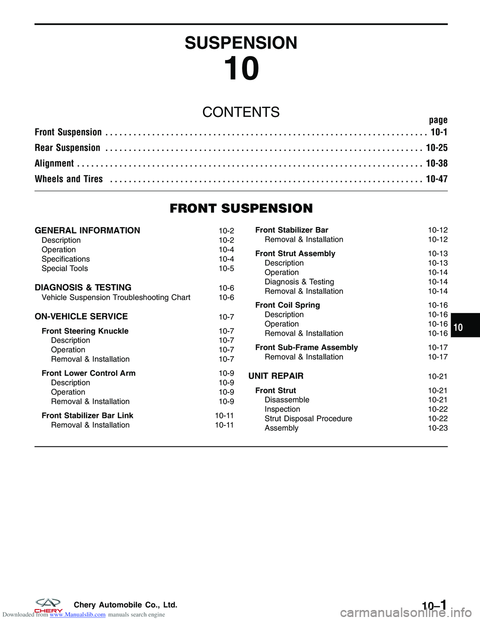
CONTENTSpage
Front Suspension ..................................................................... 10-1
Rear Suspension .................................................................... 10-25
Alignment ........................................................................\
.. 10-38
Wheels and Tires ................................................................... 10-47
FRONT SUSPENSION
GENERAL INFORMATION10-2
Description 10-2
Operation 10-4
Specifications 10-4
Special Tools 10-5
DIAGNOSIS & TESTING10-6
Vehicle Suspension Troubleshooting Chart 10-6
ON-VEHICLE SERVICE10-7
Front Steering Knuckle 10-7
Description 10-7
Operation 10-7
Removal & Installation 10-7
Front Lower Control Arm 10-9
Description 10-9
Operation 10-9
Removal & Installation 10-9
Front Stabilizer Bar Link 10-11
Removal & Installation 10-11Front Stabilizer Bar
10-12
Removal & Installation 10-12
Front Strut Assembly 10-13
Description 10-13
Operation 10-14
Diagnosis & Testing 10-14
Removal & Installation 10-14
Front Coil Spring 10-16
Description 10-16
Operation 10-16
Removal & Installation 10-16
Front Sub-Frame Assembly 10-17
Removal & Installation 10-17
UNIT REPAIR10-21
Front Strut 10-21
Disassemble 10-21
Inspection 10-22
Strut Disposal Procedure 10-22
Assembly 10-23
10
10–1Chery Automobile Co., Ltd.
Page 1307 of 1903
Downloaded from www.Manualslib.com manuals search engine DIAGNOSIS & TESTING
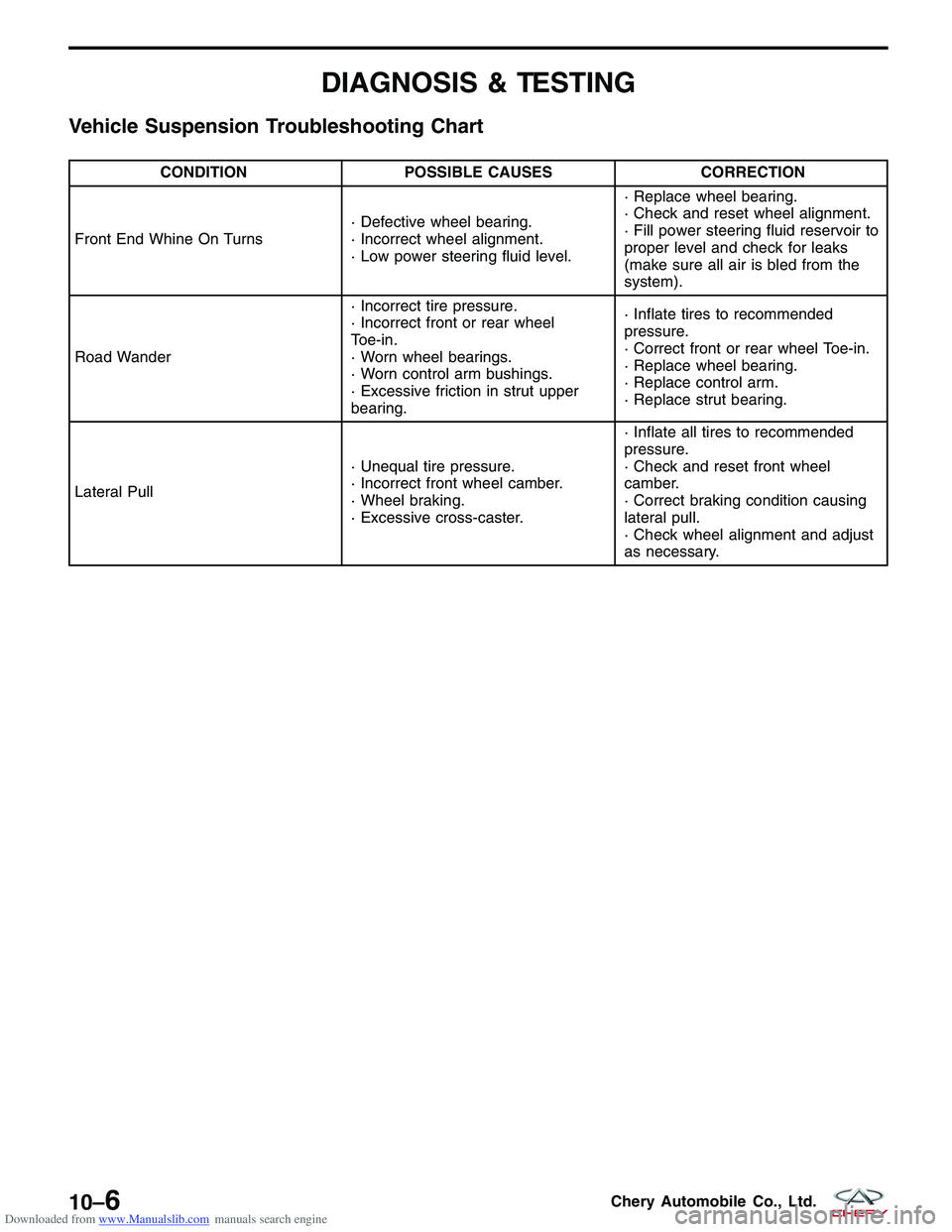
Vehicle Suspension Troubleshooting Chart
CONDITIONPOSSIBLE CAUSES CORRECTION
Front End Whine On Turns · Defective wheel bearing.
· Incorrect wheel alignment.
· Low power steering fluid level.· Replace wheel bearing.
· Check and reset wheel alignment.
· Fill power steering fluid reservoir to
proper level and check for leaks
(make sure all air is bled from the
system).
Road Wander · Incorrect tire pressure.
· Incorrect front or rear wheel
Toe-in.
· Worn wheel bearings.
· Worn control arm bushings.
· Excessive friction in strut upper
bearing.· Inflate tires to recommended
pressure.
· Correct front or rear wheel Toe-in.
· Replace wheel bearing.
· Replace control arm.
· Replace strut bearing.
Lateral Pull · Unequal tire pressure.
· Incorrect front wheel camber.
· Wheel braking.
· Excessive cross-caster.· Inflate all tires to recommended
pressure.
· Check and reset front wheel
camber.
· Correct braking condition causing
lateral pull.
· Check wheel alignment and adjust
as necessary.
10–6Chery Automobile Co., Ltd.
Page 1310 of 1903
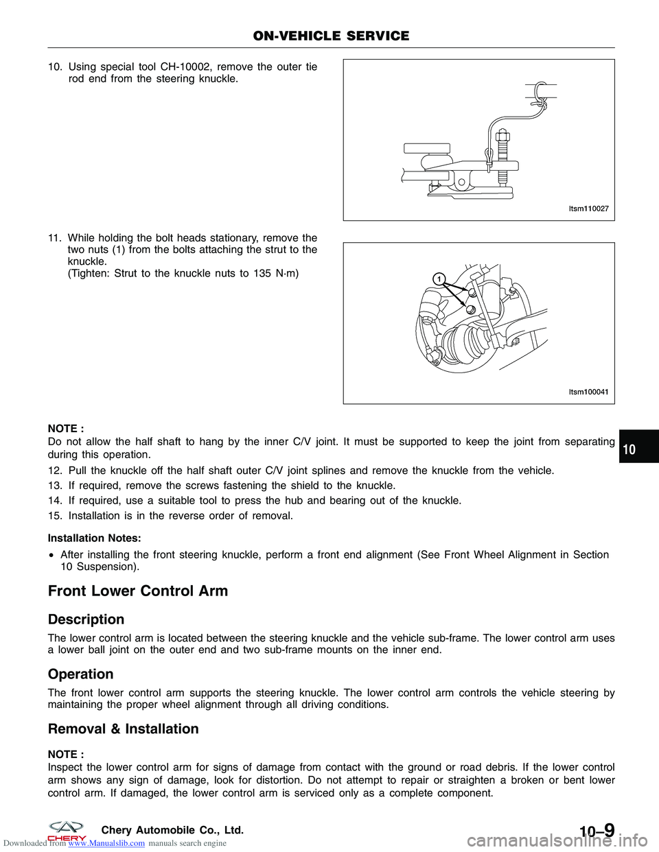
Downloaded from www.Manualslib.com manuals search engine 10. Using special tool CH-10002, remove the outer tierod end from the steering knuckle.
11. While holding the bolt heads stationary, remove the two nuts (1) from the bolts attaching the strut to the
knuckle.
(Tighten: Strut to the knuckle nuts to 135 N·m)
NOTE :
Do not allow the half shaft to hang by the inner C/V joint. It must be supported to keep the joint from separating
during this operation.
12. Pull the knuckle off the half shaft outer C/V joint splines and remove the knuckle from the vehicle.
13. If required, remove the screws fastening the shield to the knuckle.
14. If required, use a suitable tool to press the hub and bearing out of the knuckle.
15. Installation is in the reverse order of removal.
Installation Notes:
• After installing the front steering knuckle, perform a front end alignment (See Front Wheel Alignment in Section
10 Suspension).
Front Lower Control Arm
Description
The lower control arm is located between the steering knuckle and the vehicle sub-frame. The lower control arm uses
a lower ball joint on the outer end and two sub-frame mounts on the inner end.
Operation
The front lower control arm supports the steering knuckle. The lower control arm controls the vehicle steering by
maintaining the proper wheel alignment through all driving conditions.
Removal & Installation
NOTE :
Inspect the lower control arm for signs of damage from contact with the ground or road debris. If the lower control
arm shows any sign of damage, look for distortion. Do not attempt to repair or straighten a broken or bent lower
control arm. If damaged, the lower control arm is serviced only as a complete component.
ON-VEHICLE SERVICE
LTSM110027
LTSM100041
10
10–9Chery Automobile Co., Ltd.
Page 1316 of 1903
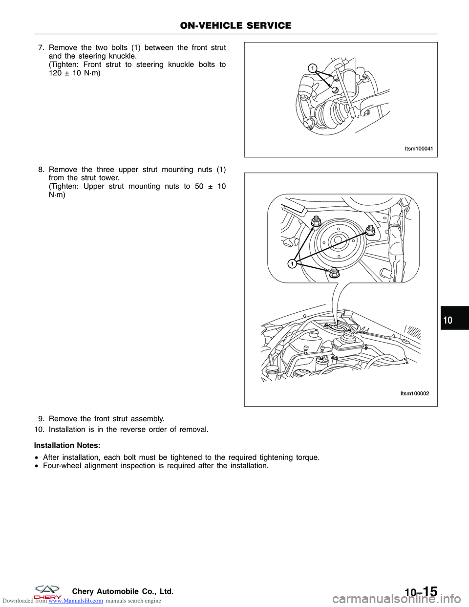
Downloaded from www.Manualslib.com manuals search engine 7. Remove the two bolts (1) between the front strutand the steering knuckle.
(Tighten: Front strut to steering knuckle bolts to
120 ± 10 N·m)
8. Remove the three upper strut mounting nuts (1) from the strut tower.
(Tighten: Upper strut mounting nuts to 50 ± 10
N·m)
9. Remove the front strut assembly.
10. Installation is in the reverse order of removal.
Installation Notes:
• After installation, each bolt must be tightened to the required tightening torque.
• Four-wheel alignment inspection is required after the installation.
ON-VEHICLE SERVICE
LTSM100041
LTSM100002
10
10–15Chery Automobile Co., Ltd.
Page 1339 of 1903
Downloaded from www.Manualslib.com manuals search engine ALIGNMENT
GENERAL INFORMATION10-39
Description 10-39
Operation 10-39
Pre-Wheel Alignment Inspection 10-39
Wheel Alignment Setup 10-40
Specifications 10-40
DIAGNOSIS & TESTING10-42
Vehicle Inspection 10-42
Tire Wear 10-42
Tire Wear Chart 10-42
Alignment Troubleshooting Chart 10-43
ON-VEHICLE SERVICE10-44
Front Wheel Alignment 10-44
Front Wheel Alignment Specifications 10-44
Front Axle Toe-In Adjustment 10-44
Front Camber Adjustment 10-44
Rear Wheel Alignment 10-45
Rear Wheel Alignment Specifications 10-45
Rear Axle Toe-In Adjustment 10-45
Rear Camber Adjustment 10-46
10–38Chery Automobile Co., Ltd.