Page 27 of 1903
Downloaded from www.Manualslib.com manuals search engine SERVICE MANUAL CHAPTERCOMPONENT / VEHICLE SYSTEM
08 - Transaxle & Transfer Case •
Transaxle Control Module (TCM)
• Automatic Transaxle Shifter Selector
• Automatic Transaxle Assembly
• Manual Transaxle Assembly
• Winter Mode Switch
• EPDE Solenoid Valve
• Backup Lamp Switch
• Integrated Torque Management (ITM) Control Module
09 - Driveline & Axle •None
10 - Suspension •None
11 - Steering •Power Steering Switch
12 - Brakes •
Antilock Brake System (ABS) Module
• Wheel Speed Sensors
• Brake Switch
• Parking Brake Switch
• Brake Fluid Level Switch
13 - Heating & Air Conditioning •
Manual Temperature Control System
• Blower Motor
• A/C Compressor
• Refrigerant Pressure Switch
14 - Restraints •
Restraints Control Module
• Seat Belt Buckle Switch
• Front Crash Sensors
• Driver Airbag
• Passenger Airbag
HOW TO LOCATE ELECTRICAL SCHEMATICS IN THE SERVICE MANUAL
01–26Chery Automobile Co., Ltd.
Page 29 of 1903
Downloaded from www.Manualslib.com manuals search engine TERMABBREVIATION
Front Left Wheel Speed Sensor FLS
Front Right Wheel Speed Sensor FRS
Rear Left Wheel Speed Sensor RCS
Rear Right Wheel Speed Sensor RRS
Ground GND
Heated Oxygen Sensor O2S
Idle Air Control IAC
Intake Air Temperature IAT
Ignition IGN
Ignition Control IC
Immobilizer Control Module ICM
Injector INJ
Input Shaft Speed Sensor ISS Sensor
Knock Sensor KS
Manifold Absolute Pressure MAP
Mass Air Flow MAF
Malfunction Indicator Lamp MIL
Oil Pressure Switch OPS
Output Shaft Speed Sensor OSS Sensor
Positive Crankcase Ventilation Valve PCV Valve
Power Supply PWR
SRS Airbag Control System SRC
Throttle Position Sensor TPS
Transaxle Control Module TCM
Turbine Speed Sensor TSS
Vehicle Identification Number VIN
Vehicle Speed Sensor VSS
HOW TO LOCATE ELECTRICAL SCHEMATICS IN THE SERVICE MANUAL
01–28Chery Automobile Co., Ltd.
Page 1364 of 1903
Downloaded from www.Manualslib.com manuals search engine GENERAL INFORMATION
Description
The steering column has been designed so that the wiring, switches, shrouds and steering wheel can be serviced
without removing the steering column from the vehicle.
1 - Horn Hood Assembly
2 - Airbag
3 - Spoke Trim Cover
4 - Adjustable Steering Column
5 - Bolt
6 - Steering Lower Shield
7 - Jacket Mounting Bracket
8 - Steering Upper Shield9 - Intermediate Shaft
10 - Lower Universal Joint
11 - Upper Universal Joint
12 - Installed Bracket
13 - Adjusting Spring
14 - Steering Wheel Nut
15 - Steering Wheel
LTSM110004
11
11 –9Chery Automobile Co., Ltd.
Page 1367 of 1903
Downloaded from www.Manualslib.com manuals search engine ON-VEHICLE SERVICE
Steering Wheel
Removal & Installation
WARNING!
Before servicing the steering column, the airbag system must be disarmed. Failure to do so may result in acci-
dental deployment of the airbag and possible personal injury (See Airbag System Disarming Procedure in Sec-
tion 14 Restraints).
NOTE :
To help maintain alignment of the spiral cable connector during reassembly, apply a small piece of tape to the spiral
cable and the steering column to keep them in alignment.1. Set the front wheels to the straight-ahead position.
2. Disconnect the negative battery cable.
3. Remove the driver airbag (See Driver Airbag Removal & Installation in Section 14 Restraints).
4. Disconnect the spiral cable electrical connector.
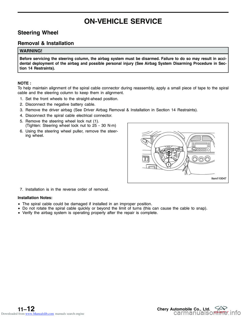
5. Remove the steering wheel lock nut (1). (Tighten: Steering wheel lock nut to 25 - 30 N·m)
6. Using the steering wheel puller, remove the steer- ing wheel.
7. Installation is in the reverse order of removal.
Installation Notes:
• The spiral cable could be damaged if installed in an improper position.
• Do not rotate the spiral cable quickly or beyond the limit of turns (this can cause the cable to snap).
• Verify the airbag system is operating properly after the repair is complete.
LTSM110047
11 –12Chery Automobile Co., Ltd.
Page 1369 of 1903
Downloaded from www.Manualslib.com manuals search engine Steering Wheel Return to Center Inspection
NOTE :
This test should be performed during a road test.
•Make smooth turns and sharp turns. Check the driving �sense�to ensure there is no difference between the left
and right turns in terms of steering force and the steering wheel returning to center.
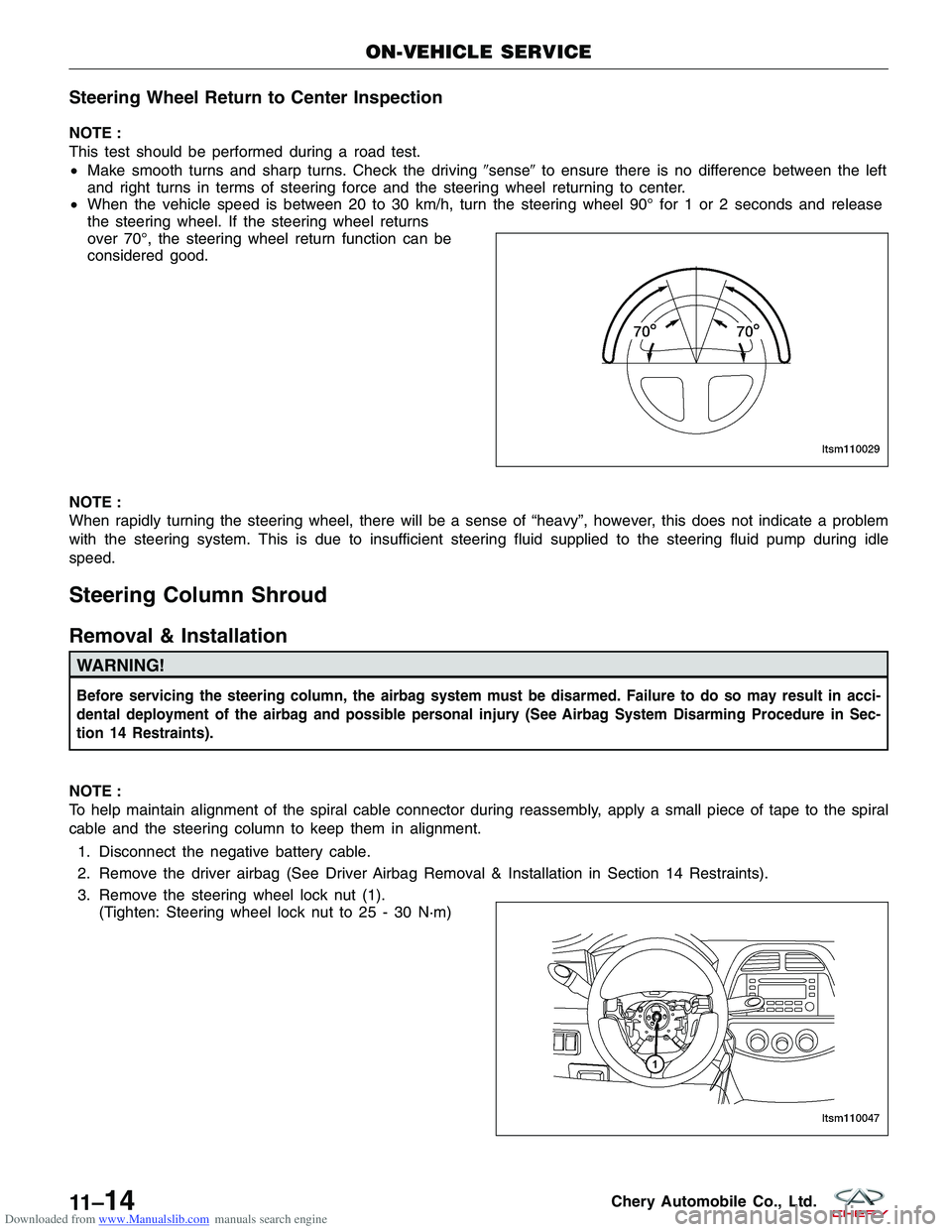
• When the vehicle speed is between 20 to 30 km/h, turn the steering wheel 90° for 1 or 2 seconds and release
the steering wheel. If the steering wheel returns
over 70°, the steering wheel return function can be
considered good.
NOTE :
When rapidly turning the steering wheel, there will be a sense of “heavy”, however, this does not indicate a problem
with the steering system. This is due to insufficient steering fluid supplied to the steering fluid pump during idle
speed.
Steering Column Shroud
Removal & Installation
WARNING!
Before servicing the steering column, the airbag system must be disarmed. Failure to do so may result in acci-
dental deployment of the airbag and possible personal injury (See Airbag System Disarming Procedure in Sec-
tion 14 Restraints).
NOTE :
To help maintain alignment of the spiral cable connector during reassembly, apply a small piece of tape to the spiral
cable and the steering column to keep them in alignment. 1. Disconnect the negative battery cable.
2. Remove the driver airbag (See Driver Airbag Removal & Installation in Section 14 Restraints).
3. Remove the steering wheel lock nut (1). (Tighten: Steering wheel lock nut to 25 - 30 N·m)
ON-VEHICLE SERVICE
LTSM110029
LTSM110047
11 –14Chery Automobile Co., Ltd.
Page 1370 of 1903
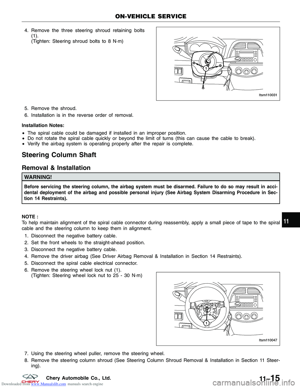
Downloaded from www.Manualslib.com manuals search engine 4. Remove the three steering shroud retaining bolts(1).
(Tighten: Steering shroud bolts to 8 N·m)
5. Remove the shroud.
6. Installation is in the reverse order of removal.
Installation Notes:
• The spiral cable could be damaged if installed in an improper position.
• Do not rotate the spiral cable quickly or beyond the limit of turns (this can cause the cable to break).
• Verify the airbag system is operating properly after the repair is complete.
Steering Column Shaft
Removal & Installation
WARNING!
Before servicing the steering column, the airbag system must be disarmed. Failure to do so may result in acci-
dental deployment of the airbag and possible personal injury (See Airbag System Disarming Procedure in Sec-
tion 14 Restraints).
NOTE :
To help maintain alignment of the spiral cable connector during reassembly, apply a small piece of tape to the spiral
cable and the steering column to keep them in alignment.
1. Disconnect the negative battery cable.
2. Set the front wheels to the straight-ahead position.
3. Disconnect the negative battery cable.
4. Remove the driver airbag (See Driver Airbag Removal & Installation in Section 14 Restraints).
5. Disconnect the spiral cable electrical connector.
6. Remove the steering wheel lock nut (1). (Tighten: Steering wheel lock nut to 25 - 30 N·m)
7. Using the steering wheel puller, remove the steering wheel.
8. Remove the steering column shroud (See Steering Column Shroud Removal & Installation in Section 11 Steer- ing).
ON-VEHICLE SERVICE
LTSM110031
LTSM110047
11
11 –15Chery Automobile Co., Ltd.
Page 1372 of 1903
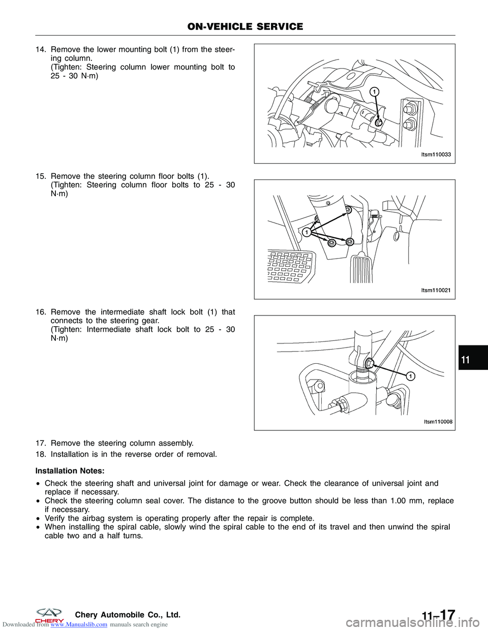
Downloaded from www.Manualslib.com manuals search engine 14. Remove the lower mounting bolt (1) from the steer-ing column.
(Tighten: Steering column lower mounting bolt to
25 - 30 N·m)
15. Remove the steering column floor bolts (1). (Tighten: Steering column floor bolts to 25 - 30
N·m)
16. Remove the intermediate shaft lock bolt (1) that connects to the steering gear.
(Tighten: Intermediate shaft lock bolt to 25 - 30
N·m)
17. Remove the steering column assembly.
18. Installation is in the reverse order of removal.
Installation Notes:
• Check the steering shaft and universal joint for damage or wear. Check the clearance of universal joint and
replace if necessary.
• Check the steering column seal cover. The distance to the groove button should be less than 1.00 mm, replace
if necessary.
• Verify the airbag system is operating properly after the repair is complete.
• When installing the spiral cable, slowly wind the spiral cable to the end of its travel and then unwind the spiral
cable two and a half turns.
ON-VEHICLE SERVICE
LTSM110033
LTSM110021
LTSM110008
11
11 –17Chery Automobile Co., Ltd.
Page 1530 of 1903
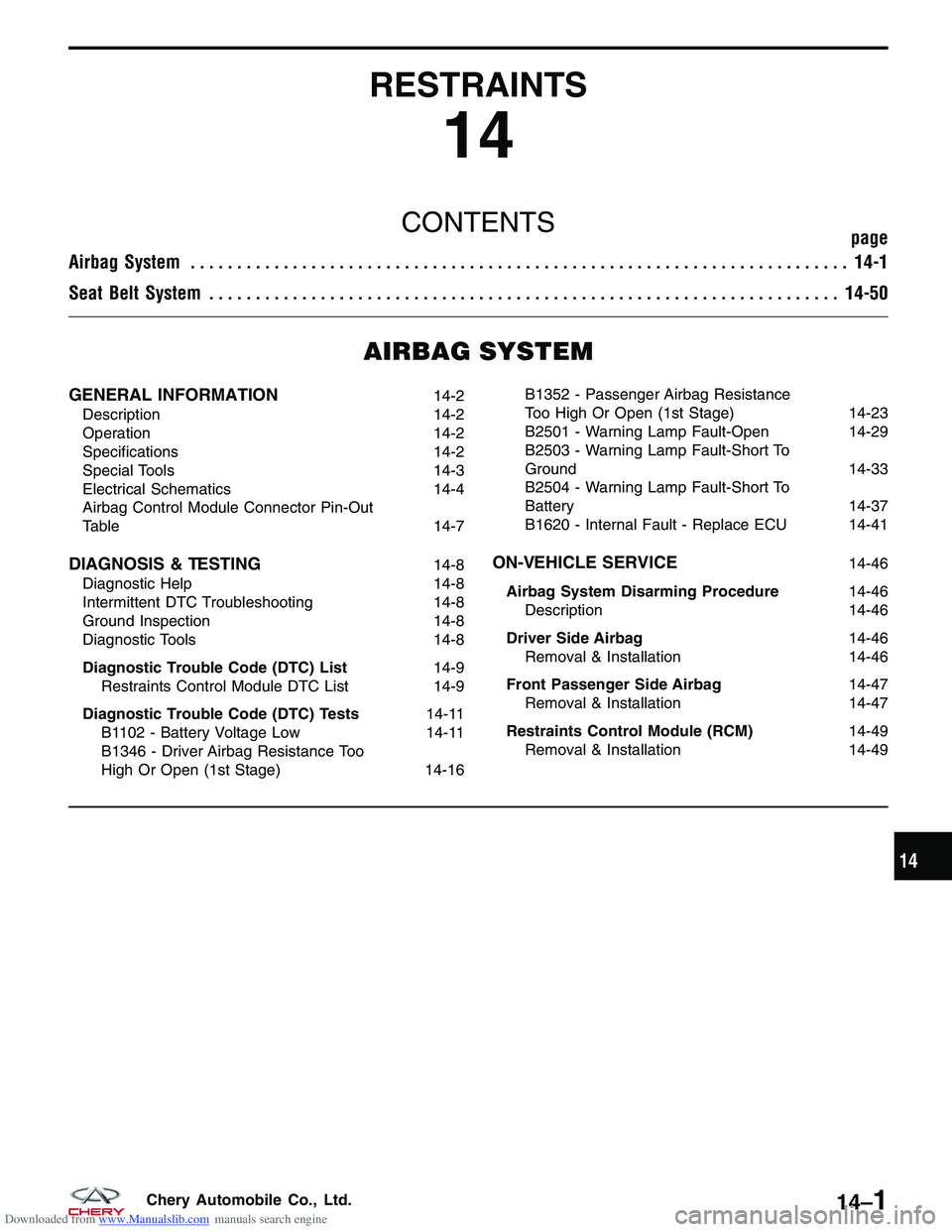
Downloaded from www.Manualslib.com manuals search engine RESTRAINTS
14
CONTENTSpage
Airbag System ....................................................................... 14-1
Seat Belt System .................................................................... 14-50
AIRBAG SYSTEM
GENERAL INFORMATION14-2
Description 14-2
Operation 14-2
Specifications 14-2
Special Tools 14-3
Electrical Schematics 14-4
Airbag Control Module Connector Pin-Out
Table 14-7
DIAGNOSIS & TESTING14-8
Diagnostic Help 14-8
Intermittent DTC Troubleshooting 14-8
Ground Inspection 14-8
Diagnostic Tools 14-8
Diagnostic Trouble Code (DTC) List 14-9
Restraints Control Module DTC List 14-9
Diagnostic Trouble Code (DTC) Tests 14-11
B1102 - Battery Voltage Low 14-11
B1346 - Driver Airbag Resistance Too
High Or Open (1st Stage) 14-16B1352 - Passenger Airbag Resistance
Too High Or Open (1st Stage)
14-23
B2501 - Warning Lamp Fault-Open 14-29
B2503 - Warning Lamp Fault-Short To
Ground 14-33
B2504 - Warning Lamp Fault-Short To
Battery 14-37
B1620 - Internal Fault - Replace ECU 14-41ON-VEHICLE SERVICE14-46
Airbag System Disarming Procedure 14-46
Description 14-46
Driver Side Airbag 14-46
Removal & Installation 14-46
Front Passenger Side Airbag 14-47
Removal & Installation 14-47
Restraints Control Module (RCM) 14-49
Removal & Installation 14-49
14
14–1Chery Automobile Co., Ltd.