Page 14 of 1903
Downloaded from www.Manualslib.com manuals search engine INTERNATIONAL SYMBOLS
International Symbols
The graphic symbols illustrated in the following International Control and Display Symbols chart are used to identify var-
ious instrument controls. The symbols correspond to the controls and displays that are located on the instrument panel.
International Control and Display Symbols
1 - High Beam
2 - Fog Lamps
3 - Headlamp, Parking Lamps, Panel Lamps
4 - Turn Signals
5 - Hazard Warning
6 - Front Windshield Washer
7 - Front Windshield Wiper
8 - Front Windshield Wiper and Washer
9 - Front Windshield Defroster
10 - Blower Motor Fan
11 - Rear Window Defroster
12 - Rear Window Wiper13 - Rear Window Washer
14 - Fuel
15 - Engine Coolant Temperature
16 - Battery Charging Condition
17 - Engine Oil
18 - Seat Belt
19 - Brake Failure
20 - Parking Brake
21 - Hood
22 - Trunk
23 - Horn
24 - Cigarette Lighter
BESM010003
01
01–13Chery Automobile Co., Ltd.
Page 305 of 1903
Downloaded from www.Manualslib.com manuals search engine PINCIRCUIT IDENTIFICATION PINCIRCUIT IDENTIFICATION
35 Sensor (GND) 76Power Steering Switch
36 Sensor (GND) 77Headlamp Switch
37 Manifold Absolute Pressure Sensor (With
1.6L Engine) 78Sensor (GND)
Air Flow Sensor (With 1.8L Engine)
38 Electronic Throttle Control Actuator
(Position Sensor) 79
Camshaft Position Sensor
39 Engine Coolant Temperature Sensor 80 GND (Power)
40 Accelerator Pedal Position Sensor 81 -
41 -
GENERAL INFORMATION
03
03–21Chery Automobile Co., Ltd.
Page 530 of 1903
Downloaded from www.Manualslib.com manuals search engine PINCIRCUIT IDENTIFICATION PINCIRCUIT IDENTIFICATION
35 Sensor (GND) 76Power Steering Switch
36 Sensor (GND) 77Headlamp Switch
37 Air Flow Sensor 78Sensor (GND)
38 Electronic Throttle Control Actuator (Position
Sensor) 79
Camshaft Position Sensor
39 Engine Coolant Temperature Sensor 80 GND (Power)
40 Accelerator Pedal Position Sensor 81 CAN-L
41 -
GENERAL INFORMATION
03–246Chery Automobile Co., Ltd.
Page 1669 of 1903
Downloaded from www.Manualslib.com manuals search engine INTERIOR LAMPS
Description
The interior lamps consist of the following:
•Key Hole Lamp
• Front Room Lamp
• Middle/Rear Courtesy/Dome Lamp
• Front Step Lamp
• Backlight Adjusting Switch
• Instrument Cluster
• Headlamp Aiming Switch
• Heated Seat Switch (LH)
• Heated Seat Switch (RH)
• Air Control Panel
• Front Fog Lamp Switch
• Rear Fog Lamp Switch
• Console Power Socket (Illumination)
• Door Mirror Remote Control Switch
• Main Power Window And Door Lock/Unlock Switch
• Front Power Window Switch (RH)
• Rear Power Window Switch (LH)
• Rear Power Window Switch (RH)
• Audio
Operation
The key hole lamp and front/middle/rear courtesy lamps are controlled by the BCM. Front step lamps are controlled
by the door lock switch. When the door is open, the front step lamp will light up automatically. Other lamps are
controlled by the lighting and turn signal switch.
15
15–85Chery Automobile Co., Ltd.
Page 1729 of 1903

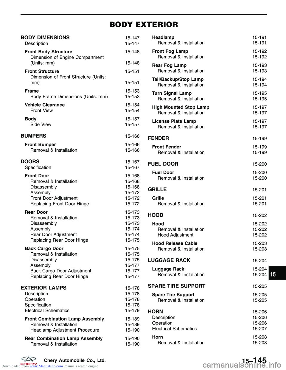
Downloaded from www.Manualslib.com manuals search engine BODY EXTERIOR
BODY DIMENSIONS15-147
Description 15-147
Front Body Structure 15-148
Dimension of Engine Compartment
(Units: mm) 15-148
Front Structure 15-151
Dimension of Front Structure (Units:
mm) 15-151
Frame 15-153
Body Frame Dimensions (Units: mm) 15-153
Vehicle Clearance 15-154
Front View 15-154
Body 15-157
Side View 15-157
BUMPERS15-166
Front Bumper 15-166
Removal & Installation 15-166
DOORS15-167
Specification 15-167
Front Door 15-168
Removal & Installation 15-168
Disassembly 15-168
Assembly 15-172
Front Door Adjustment 15-172
Replacing Front Door Hinge 15-172
Rear Door 15-173
Removal & Installation 15-173
Disassembly 15-173
Assembly 15-174
Rear Door Adjustment 15-174
Replacing Rear Door Hinge 15-175
Back Cargo Door 15-175
Removal & Installation 15-175
Disassembly 15-175
Assembly 15-177
Back Cargo Door Adjustment 15-177
Replacing Rear Door Hinge 15-177
EXTERIOR LAMPS15-178
Description 15-178
Operation 15-178
Specification 15-178
Electrical Schematics 15-179
Front Combination Lamp Assembly 15-189
Removal & Installation 15-189
Headlamp Adjustment Procedure 15-190
Rear Combination Lamp Assembly 15-190
Removal & Installation 15-190Headlamp
15-191
Removal & Installation 15-191
Front Fog Lamp 15-192
Removal & Installation 15-192
Rear Fog Lamp 15-193
Removal & Installation 15-193
Tail/Backup/Stop Lamp 15-194
Removal & Installation 15-194
Turn Signal Lamp 15-195
Removal & Installation 15-195
High Mounted Stop Lamp 15-197
Removal & Installation 15-197
License Plate Lamp 15-197
Removal & Installation 15-197
FENDER15-199
Front Fender 15-199
Removal & Installation 15-199
FUEL DOOR15-200
Fuel Door 15-200
Removal & Installation 15-200
GRILLE15-201
Grille 15-201
Removal & Installation 15-201
HOOD15-202
Hood 15-202
Removal & Installation 15-202
Hood Adjustment 15-202
Hood Release Cable 15-203
Removal & Installation 15-203
LUGGAGE RACK15-204
Luggage Rack 15-204
Removal & Installation 15-204
SPARE TIRE SUPPORT15-205
Spare Tire Support 15-205
Removal & Installation 15-205
HORN15-206
Description 15-206
Operation 15-206
Electrical Schematics 15-207
Horn 15-208
Removal & Installation 15-208
15
15–145Chery Automobile Co., Ltd.
Page 1750 of 1903
Downloaded from www.Manualslib.com manuals search engine BUMPERS
Front Bumper
Removal & Installation
1. Remove the left and right headlamp (See Headlamp Removal & Installation in Section 15 Body & Accessories).
2. Remove the three front bumper mounting bolts (1).
3. Remove the front bumper side mounting bolts and the connecting bolts (3) from the front wheel house.
4. Raise the vehicle and remove the mounting bolts (2) under the front bumper.
5. Disconnect the front fog light electrical connectors and remove the front bumper.
6. Installation is in the reverse order of removal.
LTSM150074
15–166Chery Automobile Co., Ltd.
Page 1762 of 1903

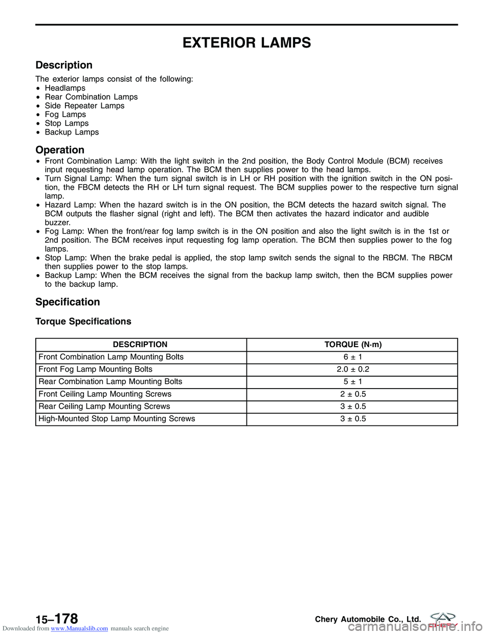
Downloaded from www.Manualslib.com manuals search engine EXTERIOR LAMPS
Description
The exterior lamps consist of the following:
•Headlamps
• Rear Combination Lamps
• Side Repeater Lamps
• Fog Lamps
• Stop Lamps
• Backup Lamps
Operation
•Front Combination Lamp: With the light switch in the 2nd position, the Body Control Module (BCM) receives
input requesting head lamp operation. The BCM then supplies power to the head lamps.
• Turn Signal Lamp: When the turn signal switch is in LH or RH position with the ignition switch in the ON posi-
tion, the FBCM detects the RH or LH turn signal request. The BCM supplies power to the respective turn signal
lamp.
• Hazard Lamp: When the hazard switch is in the ON position, the BCM detects the hazard switch signal. The
BCM outputs the flasher signal (right and left). The BCM then activates the hazard indicator and audible
buzzer.
• Fog Lamp: When the front/rear fog lamp switch is in the ON position and also the light switch is in the 1st or
2nd position. The BCM receives input requesting fog lamp operation. The BCM then supplies power to the fog
lamps.
• Stop Lamp: When the brake pedal is applied, the stop lamp switch sends the signal to the RBCM. The RBCM
then supplies power to the stop lamps.
• Backup Lamp: When the BCM receives the signal from the backup lamp switch, then the BCM supplies power
to the backup lamp.
Specification
Torque Specifications
DESCRIPTION TORQUE (N·m)
Front Combination Lamp Mounting Bolts 6 ± 1
Front Fog Lamp Mounting Bolts 2.0 ± 0.2
Rear Combination Lamp Mounting Bolts 5 ± 1
Front Ceiling Lamp Mounting Screws 2 ± 0.5
Rear Ceiling Lamp Mounting Screws 3 ± 0.5
High-Mounted Stop Lamp Mounting Screws 3 ± 0.5
15–178Chery Automobile Co., Ltd.
Page 1763 of 1903
Downloaded from www.Manualslib.com manuals search engine Electrical Schematics
Headlamp Aiming System (Page 1 of 2)
EXTERIOR LAMPS
LTSMW150015T
15
15–179Chery Automobile Co., Ltd.