2009 CHERY TIGGO low beam
[x] Cancel search: low beamPage 14 of 1903

Downloaded from www.Manualslib.com manuals search engine INTERNATIONAL SYMBOLS
International Symbols
The graphic symbols illustrated in the following International Control and Display Symbols chart are used to identify var-
ious instrument controls. The symbols correspond to the controls and displays that are located on the instrument panel.
International Control and Display Symbols
1 - High Beam
2 - Fog Lamps
3 - Headlamp, Parking Lamps, Panel Lamps
4 - Turn Signals
5 - Hazard Warning
6 - Front Windshield Washer
7 - Front Windshield Wiper
8 - Front Windshield Wiper and Washer
9 - Front Windshield Defroster
10 - Blower Motor Fan
11 - Rear Window Defroster
12 - Rear Window Wiper13 - Rear Window Washer
14 - Fuel
15 - Engine Coolant Temperature
16 - Battery Charging Condition
17 - Engine Oil
18 - Seat Belt
19 - Brake Failure
20 - Parking Brake
21 - Hood
22 - Trunk
23 - Horn
24 - Cigarette Lighter
BESM010003
01
01–13Chery Automobile Co., Ltd.
Page 505 of 1903

Downloaded from www.Manualslib.com manuals search engine Operation
When engine is running, the high and low parts of the teeth causes the gap with the sensor to change. The changing
gap causes the magnetic field near the sensor to change. Due to the changing magnetic field, the voltage from the
sensor changes. The Engine Control Module (ECM) detects the voltage signal and identify piston position and cyl-
inder timing.
Removal & Installation
1. Disconnect the negative battery cable.
2. Disconnect the CMP sensor electrical connector.
3. Remove the CMP sensor (1) retaining bolt.(Tighten: Camshaft position sensor retaining bolt to
7 N·m)
4. Pull the CMP sensor up and take out of the cylin- der head cover.
5. Installation is in the reverse order of removal.
Vehicle Speed Sensor
Description
The vehicle speed sensor is mounted to the transaxle housing.
Operation
The vehicle speed sensor generates a signal sent to the Engine Control Module (ECM) and the Transaxle Control
Module (TCM) utilize to perform engine and transaxle functions.
Removal & Installation
1. Disconnect the negative battery cable.
2. Disconnect the vehicle speed sensor connector.
3. Remove the vehicle speed sensor mounting bolt (1).
(Tighten: Vehicle speed sensor mounting bolt to 10
N·m)
4. Remove the vehicle speed sensor carefully.
5. Installation is in the reverse order of removal.
Accelerator Sensor
Description
The accelerator sensor is located on the right front crossbeam.
ON-VEHICLE SERVICE
BESM030016
BESM030024
03
03–221Chery Automobile Co., Ltd.
Page 716 of 1903

Downloaded from www.Manualslib.com manuals search engine 4. Remove the air flow sensor retaining bolts (1).(Tighten: Air flow sensor retaining bolts to 5 N·m)
5. Pull sensor up and take out of the air cleaner case.
6. Installation is in the reverse order of removal.
Accelerator Sensor
Description
The accelerator sensor is located on the right front crossbeam.
Operation
The accelerator sensor monitors the road conditions. It sends a signal to the ECM, the ECM determines if a possible
misfire condition exists.
Removal & Installation
1. Disconnect the negative battery cable.
2. Disconnect the accelerator sensor connect.
3. Remove the accelerator sensor (1).
4. Installation is in the reverse order of removal.
Speed Control System
Description
The Speed Control System allows a driver to keep the vehicle at a predetermined speed without depressing the
accelerator pedal. The driver can set vehicle speed in advance between approximately 25 km/h and 130 km/h.
ECM controls throttle angle of electronic throttle control actuator to regulate engine speed.
If any malfunction occurs in the Speed Control System, it automatically deactivates the system and the cruise indi-
cator flashes.
ON-VEHICLE SERVICE
BESM030029
LTSM030030
03–432Chery Automobile Co., Ltd.
Page 1276 of 1903
Downloaded from www.Manualslib.com manuals search engine GENERAL INFORMATION
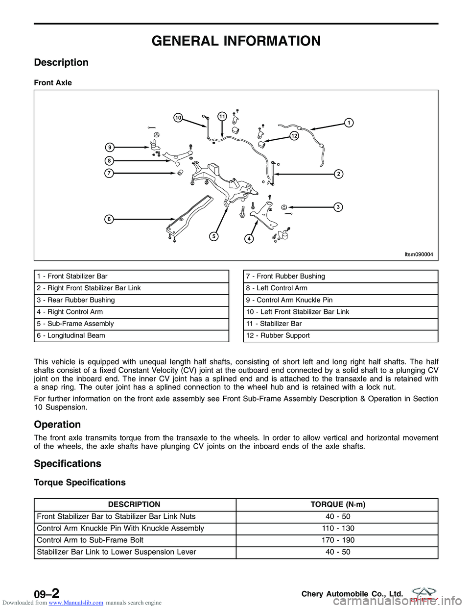
Description
This vehicle is equipped with unequal length half shafts, consisting of short left and long right half shafts. The half
shafts consist of a fixed Constant Velocity (CV) joint at the outboard end connected by a solid shaft to a plunging CV
joint on the inboard end. The inner CV joint has a splined end and is attached to the transaxle and is retained with
a snap ring. The outer joint has a splined connection to the wheel hub and is retained with a lock nut.
For further information on the front axle assembly see Front Sub-Frame Assembly Description & Operation in Section
10 Suspension.
Operation
The front axle transmits torque from the transaxle to the wheels. In order to allow vertical and horizontal movement
of the wheels, the axle shafts have plunging CV joints on the inboard ends of the axle shafts.
Specifications
Torque Specifications
DESCRIPTIONTORQUE (N·m)
Front Stabilizer Bar to Stabilizer Bar Link Nuts 40 - 50
Control Arm Knuckle Pin With Knuckle Assembly 110 - 130
Control Arm to Sub-Frame Bolt 170 - 190
Stabilizer Bar Link to Lower Suspension Lever 40 - 50
Front Axle
1 - Front Stabilizer Bar
2 - Right Front Stabilizer Bar Link
3 - Rear Rubber Bushing
4 - Right Control Arm
5 - Sub-Frame Assembly
6 - Longitudinal Beam7 - Front Rubber Bushing
8 - Left Control Arm
9 - Control Arm Knuckle Pin
10 - Left Front Stabilizer Bar Link
11 - Stabilizer Bar
12 - Rubber Support
LTSM090004
09–2Chery Automobile Co., Ltd.
Page 1277 of 1903
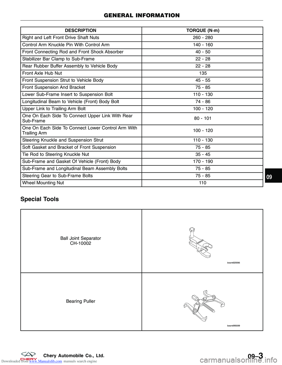
Downloaded from www.Manualslib.com manuals search engine DESCRIPTIONTORQUE (N·m)
Right and Left Front Drive Shaft Nuts 260 - 280
Control Arm Knuckle Pin With Control Arm 140 - 160
Front Connecting Rod and Front Shock Absorber 40 - 50
Stabilizer Bar Clamp to Sub-Frame 22 - 28
Rear Rubber Buffer Assembly to Vehicle Body 22 - 28
Front Axle Hub Nut 135
Front Suspension Strut to Vehicle Body 45 - 55
Front Suspension And Bracket 75 - 85
Lower Sub-Frame Insert to Suspension Bolt 110 - 130
Longitudinal Beam to Vehicle (Front) Body Bolt 74 - 86
Upper Link to Trailing Arm Bolt 100 - 120
One On Each Side To Connect Upper Link With Rear
Sub-Frame 80 - 101
One On Each Side To Connect Lower Control Arm With
Trailing Arm 100 - 120
Steering Knuckle and Suspension Strut 110 - 130
Soft Gasket and Bracket of Front Suspension 75 - 85
Tie Rod to Steering Knuckle Nut 35 - 45
Sub-Frame and Gasket Of Vehicle (Front) Body 170 - 190
Sub-Frame and Longitudinal Beam Assembly Bolts 75 - 85
Steering Gear to Sub-Frame Bolts 75 - 85
Wheel Mounting Nut \
\
11 0
Special Tools
Ball Joint Separator CH-10002
Bearing Puller
GENERAL INFORMATION
09
09–3Chery Automobile Co., Ltd.
Page 1284 of 1903
Downloaded from www.Manualslib.com manuals search engine Specifications
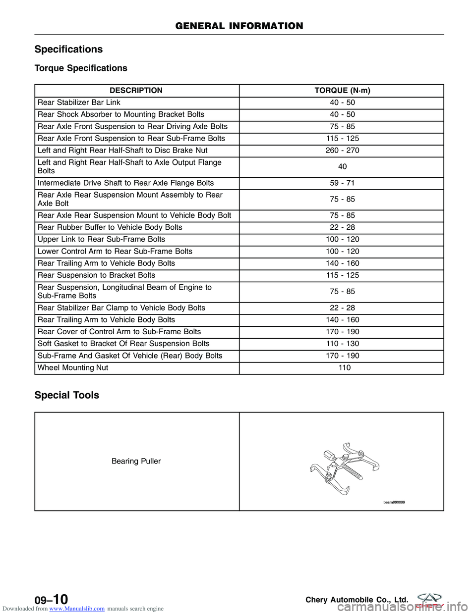
Torque Specifications
DESCRIPTIONTORQUE (N·m)
Rear Stabilizer Bar Link 40 - 50
Rear Shock Absorber to Mounting Bracket Bolts 40 - 50
Rear Axle Front Suspension to Rear Driving Axle Bolts 75 - 85
Rear Axle Front Suspension to Rear Sub-Frame Bolts 115 - 125
Left and Right Rear Half-Shaft to Disc Brake Nut 260 - 270
Left and Right Rear Half-Shaft to Axle Output Flange
Bolts 40
Intermediate Drive Shaft to Rear Axle Flange Bolts 59 - 71
Rear Axle Rear Suspension Mount Assembly to Rear
Axle Bolt 75-85
Rear Axle Rear Suspension Mount to Vehicle Body Bolt 75 - 85
Rear Rubber Buffer to Vehicle Body Bolts 22 - 28
Upper Link to Rear Sub-Frame Bolts 100 - 120
Lower Control Arm to Rear Sub-Frame Bolts 100 - 120
Rear Trailing Arm to Vehicle Body Bolts 140 - 160
Rear Suspension to Bracket Bolts 115 - 125
Rear Suspension, Longitudinal Beam of Engine to
Sub-Frame Bolts 75-85
Rear Stabilizer Bar Clamp to Vehicle Body Bolts 22 - 28
Rear Trailing Arm to Vehicle Body Bolts 140 - 160
Rear Cover of Control Arm to Sub-Frame Bolts 170 - 190
Soft Gasket to Bracket Of Rear Suspension Bolts 110 - 130
Sub-Frame And Gasket Of Vehicle (Rear) Body Bolts 170 - 190
Wheel Mounting Nut \
\
11 0
Special Tools
Bearing Puller
GENERAL INFORMATION
09–10Chery Automobile Co., Ltd.
Page 1305 of 1903
Downloaded from www.Manualslib.com manuals search engine WARNING!
Do not remove the strut rod nut while the strut assembly is installed in the vehicle, or before the coil spring is
compressed with a spring compressor. The spring is held under high pressure and must be compressed before
the strut rod nut can be removed.
CAUTION:
At no time when servicing a vehicle can a sheet metal screw, bolt, or other metal fastener be
installed in the shock tower to replace the original plastic clamp. It may come in contact with the
strut or coil spring.
CAUTION:
The wheel bearing will be damaged if the vehicle is rolled with the axle shaft hub nut loose.
Operation
The front suspension utilizes a MacPherson strut system. This suspension system incorporates a strut assembly that
takes the place of the upper arm and ball joint. The strut performs the function of a shock absorber and is encom-
passed by a coil spring.
Specifications
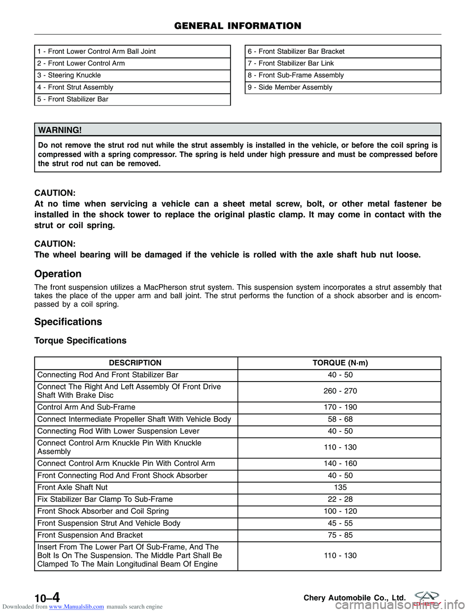
Torque Specifications
DESCRIPTIONTORQUE (N·m)
Connecting Rod And Front Stabilizer Bar 40 - 50
Connect The Right And Left Assembly Of Front Drive
Shaft With Brake Disc 260 - 270
Control Arm And Sub-Frame 170 - 190
Connect Intermediate Propeller Shaft With Vehicle Body 58 - 68
Connecting Rod With Lower Suspension Lever 40 - 50
Connect Control Arm Knuckle Pin With Knuckle
Assembly 110 - 130
Connect Control Arm Knuckle Pin With Control Arm 140 - 160
Front Connecting Rod And Front Shock Absorber 40 - 50
Front Axle Shaft Nut 135
Fix Stabilizer Bar Clamp To Sub-Frame 22 - 28
Front Shock Absorber and Coil Spring 100 - 120
Front Suspension Strut And Vehicle Body 45 - 55
Front Suspension And Bracket 75 - 85
Insert From The Lower Part Of Sub-Frame, And The
Bolt Is On The Suspension. The Middle Part Shall Be
Clamped To The Main Longitudinal Beam Of Engine 110 - 130
1 - Front Lower Control Arm Ball Joint
2 - Front Lower Control Arm
3 - Steering Knuckle
4 - Front Strut Assembly
5 - Front Stabilizer Bar6 - Front Stabilizer Bar Bracket
7 - Front Stabilizer Bar Link
8 - Front Sub-Frame Assembly
9 - Side Member Assembly
GENERAL INFORMATION
LTSM100008
10–4Chery Automobile Co., Ltd.
Page 1306 of 1903
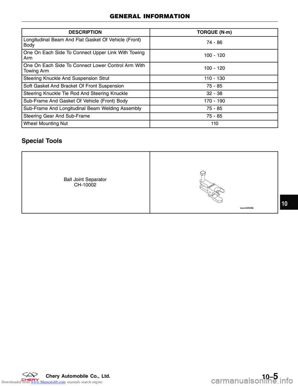
Downloaded from www.Manualslib.com manuals search engine DESCRIPTIONTORQUE (N·m)
Longitudinal Beam And Flat Gasket Of Vehicle (Front)
Body 74-86
One On Each Side To Connect Upper Link With Towing
Arm 100 - 120
One On Each Side To Connect Lower Control Arm With
Towing Arm 100 - 120
Steering Knuckle And Suspension Strut 110 - 130
Soft Gasket And Bracket Of Front Suspension 75 - 85
Steering Knuckle Tie Rod And Steering Knuckle 32 - 38
Sub-Frame And Gasket Of Vehicle (Front) Body 170 - 190
Sub-Frame And Longitudinal Beam Welding Assembly 75 - 85
Steering Gear And Sub-Frame 75 - 85
Wheel Mounting Nut \
\
110
Special Tools
Ball Joint Separator
CH-10002
GENERAL INFORMATION
10
10–5Chery Automobile Co., Ltd.