Page 1329 of 1903

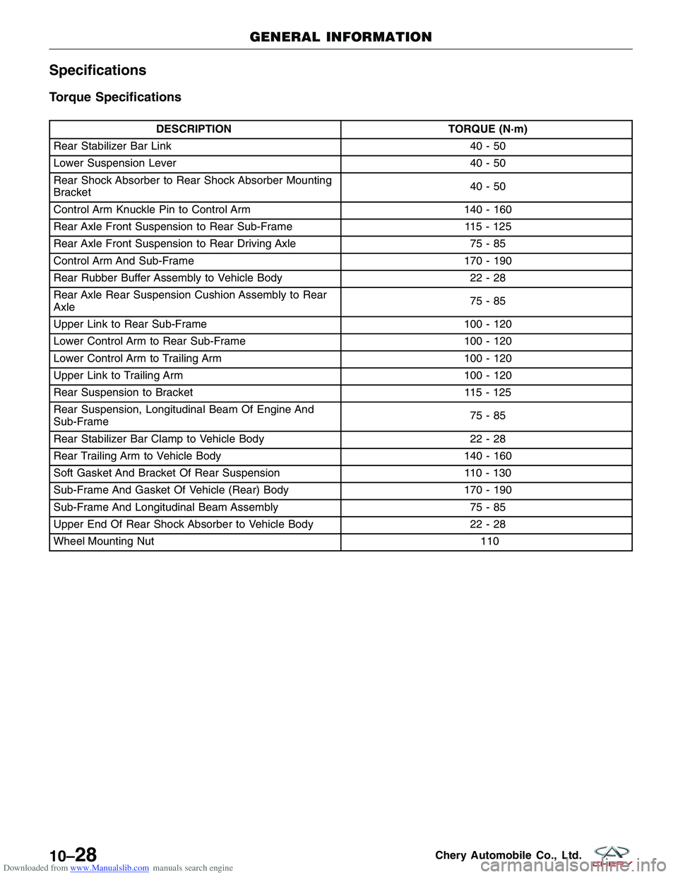
Downloaded from www.Manualslib.com manuals search engine Specifications
Torque Specifications
DESCRIPTIONTORQUE (N·m)
Rear Stabilizer Bar Link 40 - 50
Lower Suspension Lever 40 - 50
Rear Shock Absorber to Rear Shock Absorber Mounting
Bracket 40-50
Control Arm Knuckle Pin to Control Arm 140 - 160
Rear Axle Front Suspension to Rear Sub-Frame 115 - 125
Rear Axle Front Suspension to Rear Driving Axle 75 - 85
Control Arm And Sub-Frame 170 - 190
Rear Rubber Buffer Assembly to Vehicle Body 22 - 28
Rear Axle Rear Suspension Cushion Assembly to Rear
Axle 75-85
Upper Link to Rear Sub-Frame 100 - 120
Lower Control Arm to Rear Sub-Frame 100 - 120
Lower Control Arm to Trailing Arm 100 - 120
Upper Link to Trailing Arm 100 - 120
Rear Suspension to Bracket 115 - 125
Rear Suspension, Longitudinal Beam Of Engine And
Sub-Frame 75-85
Rear Stabilizer Bar Clamp to Vehicle Body 22 - 28
Rear Trailing Arm to Vehicle Body 140 - 160
Soft Gasket And Bracket Of Rear Suspension 110 - 130
Sub-Frame And Gasket Of Vehicle (Rear) Body 170 - 190
Sub-Frame And Longitudinal Beam Assembly 75 - 85
Upper End Of Rear Shock Absorber to Vehicle Body 22 - 28
Wheel Mounting Nut \
11
0
GENERAL INFORMATION
10–28Chery Automobile Co., Ltd.
Page 1636 of 1903

Downloaded from www.Manualslib.com manuals search engine INSTRUMENT CLUSTER
Description
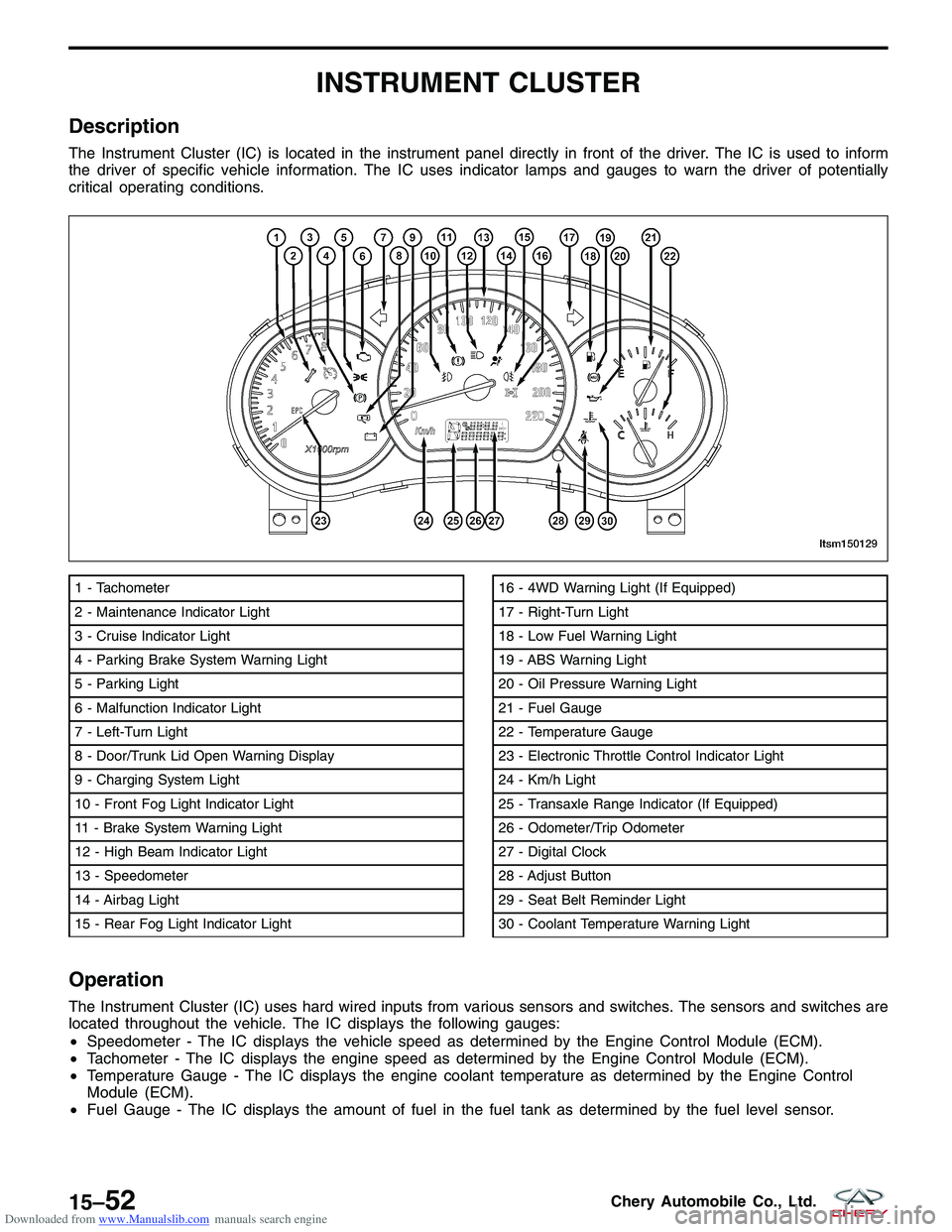
The Instrument Cluster (IC) is located in the instrument panel directly in front of the driver. The IC is used to inform
the driver of specific vehicle information. The IC uses indicator lamps and gauges to warn the driver of potentially
critical operating conditions.
Operation
The Instrument Cluster (IC) uses hard wired inputs from various sensors and switches. The sensors and switches are
located throughout the vehicle. The IC displays the following gauges:
•Speedometer - The IC displays the vehicle speed as determined by the Engine Control Module (ECM).
• Tachometer - The IC displays the engine speed as determined by the Engine Control Module (ECM).
• Temperature Gauge - The IC displays the engine coolant temperature as determined by the Engine Control
Module (ECM).
• Fuel Gauge - The IC displays the amount of fuel in the fuel tank as determined by the fuel level sensor.
1 - Tachometer
2 - Maintenance Indicator Light
3 - Cruise Indicator Light
4 - Parking Brake System Warning Light
5 - Parking Light
6 - Malfunction Indicator Light
7 - Left-Turn Light
8 - Door/Trunk Lid Open Warning Display
9 - Charging System Light
10 - Front Fog Light Indicator Light
11 - Brake System Warning Light
12 - High Beam Indicator Light
13 - Speedometer
14 - Airbag Light
15 - Rear Fog Light Indicator Light16 - 4WD Warning Light (If Equipped)
17 - Right-Turn Light
18 - Low Fuel Warning Light
19 - ABS Warning Light
20 - Oil Pressure Warning Light
21 - Fuel Gauge
22 - Temperature Gauge
23 - Electronic Throttle Control Indicator Light
24 - Km/h Light
25 - Transaxle Range Indicator (If Equipped)
26 - Odometer/Trip Odometer
27 - Digital Clock
28 - Adjust Button
29 - Seat Belt Reminder Light
30 - Coolant Temperature Warning Light
LTSM150129
15–52Chery Automobile Co., Ltd.
Page 1646 of 1903

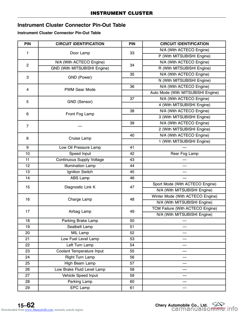
Downloaded from www.Manualslib.com manuals search engine Instrument Cluster Connector Pin-Out Table
Instrument Cluster Connector Pin-Out Table
PINCIRCUIT IDENTIFICATION PINCIRCUIT IDENTIFICATION
1 Door Lamp 33N/A (With ACTECO Engine)
P (With MITSUBISHI Engine)
2 N/A (With ACTECO Engine)
34N/A (With ACTECO Engine)
GND (With MITSUBISHI Engine) R (With MITSUBISHI Engine)
3 GND (Power) 35
N/A (With ACTECO Engine)
N (With MITSUBISHI Engine)
4 PWM Gear Mode 36
N/A (With ACTECO Engine)
Auto Mode (With MITSUBISHI Engine)
5 GND (Sensor) 37
N/A (With ACTECO Engine)
4 (With MITSUBISHI Engine)
6 Front Fog Lamp 38
N/A (With ACTECO Engine)
3 (With MITSUBISHI Engine)
7— 39
N/A (With ACTECO Engine)
2 (With MITSUBISHI Engine)
8 Cruise Lamp 40
N/A (With ACTECO Engine)
1 (With MITSUBISHI Engine)
9 Low Oil Pressure Lamp 41—
10 Speed Input 42Rear Fog Lamp
11 Continuous Supply Voltage 43—
12 Illumination Lamp 44—
13 Ignition Switch 45—
14 ABS Lamp 46—
15 Diagnostic Link K 47Sport Mode (With ACTECO Engine)
N/A (With MITSUBISHI Engine)
16 Charge Lamp 48Winter Mode (With ACTECO Engine)
N/A (With MITSUBISHI Engine)
17 Airbag Lamp 49TCM Failure (With ACTECO Engine)
N/A (With MITSUBISHI Engine)
18 Parking Brake Lamp 50—
19 Seatbelt Lamp 51—
20 MIL Lamp 52—
21 Low Fuel Level Lamp 53—
22 Left Turn Lamp 54—
23 Coolant Temperature Input 55—
24 Right Turn Lamp 56—
25 High Beam Lamp 57—
26 Low Brake Fluid Level Lamp 58—
27 Vehicle Speed Input 59—
28 Parking Lamp 60—
29 EPC Lamp 61—
INSTRUMENT CLUSTER
15–62Chery Automobile Co., Ltd.
Page 1736 of 1903

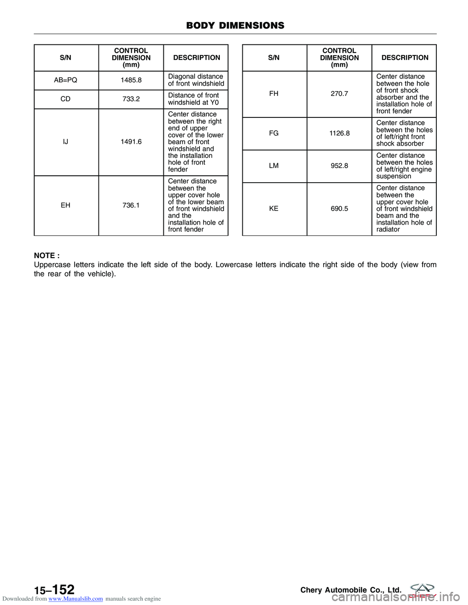
Downloaded from www.Manualslib.com manuals search engine NOTE :
Uppercase letters indicate the left side of the body. Lowercase letters indicate the right side of the body (view from
the rear of the vehicle).
S/NCONTROL
DIMENSION (mm) DESCRIPTION
AB=PQ 1485.8 Diagonal distance
of front windshield
CD 733.2Distance of front
windshield at Y0
IJ 1491.6Center distance
between the right
end of upper
cover of the lower
beam of front
windshield and
the installation
hole of front
fender
EH 736.1Center distance
between the
upper cover hole
of the lower beam
of front windshield
and the
installation hole of
front fenderS/N
CONTROL
DIMENSION (mm) DESCRIPTION
FH 270.7 Center distance
between the hole
of front shock
absorber and the
installation hole of
front fender
FG 1126.8Center distance
between the holes
of left/right front
shock absorber
LM 952.8Center distance
between the holes
of left/right engine
suspension
KE 690.5Center distance
between the
upper cover hole
of front windshield
beam and the
installation hole of
radiator
BODY DIMENSIONS
LTSM150001
15–152Chery Automobile Co., Ltd.
Page 1773 of 1903
Downloaded from www.Manualslib.com manuals search engine Front Combination Lamp Assembly
Removal & Installation
1. Open the hood.
2. Disconnect the turn signal lamp.
3. Disconnect the high/low beam front combinationlamp.
4. Remove the three front combination lamp assem- bly mounting bolts (1).
5. Carefully remove the front combination lamp assembly.
6. Installation is in the reverse order of removal.
1 Turn Signal Lamp
Bulb 12 V (21 W)
2 Headlamp Bulb
Front Position Lamp Bulb 12 V (55 W)
12V(5W)
EXTERIOR LAMPS
LTSM150037
LTSM150125
15
15–189Chery Automobile Co., Ltd.
Page 1776 of 1903
Downloaded from www.Manualslib.com manuals search engine 5. Carefully remove the bulb (1) for the high/lowbeam headlamp.
6. Replace the bulb with a new bulb as needed.
7. Installation is in the reverse order of removal.
Front Fog Lamp
Removal & Installation
1. Remove the front bumper (See Front Bumper Removal & Installation in Section 15 Body &
Accessories).
2. Disconnect the fog lamp.
3. Remove three mounting nuts (1).
EXTERIOR LAMPS
LTSM150141
LTSM150038
15–192Chery Automobile Co., Ltd.
Page 1868 of 1903
Downloaded from www.Manualslib.com manuals search engine Body Fuse and Relay Box
Description
The body fuse and relay box houses many of the fuses and relays for the vehicle’s electrical system. The body fuse
and relay box is situated on the left front side of the interior of the cabin and under the instrument panel, which is
mounted on the cross beam of the instrument panel. All the fuses and relays cannot be serviced it must be replaced
as a unit.
Operation
When a circuit fails, the fuse will blow and remove current from the circuit.
Turn off the ignition switch, and then replace the fuse.
GENERAL INFORMATION
16–42Chery Automobile Co., Ltd.