Page 25 of 1903

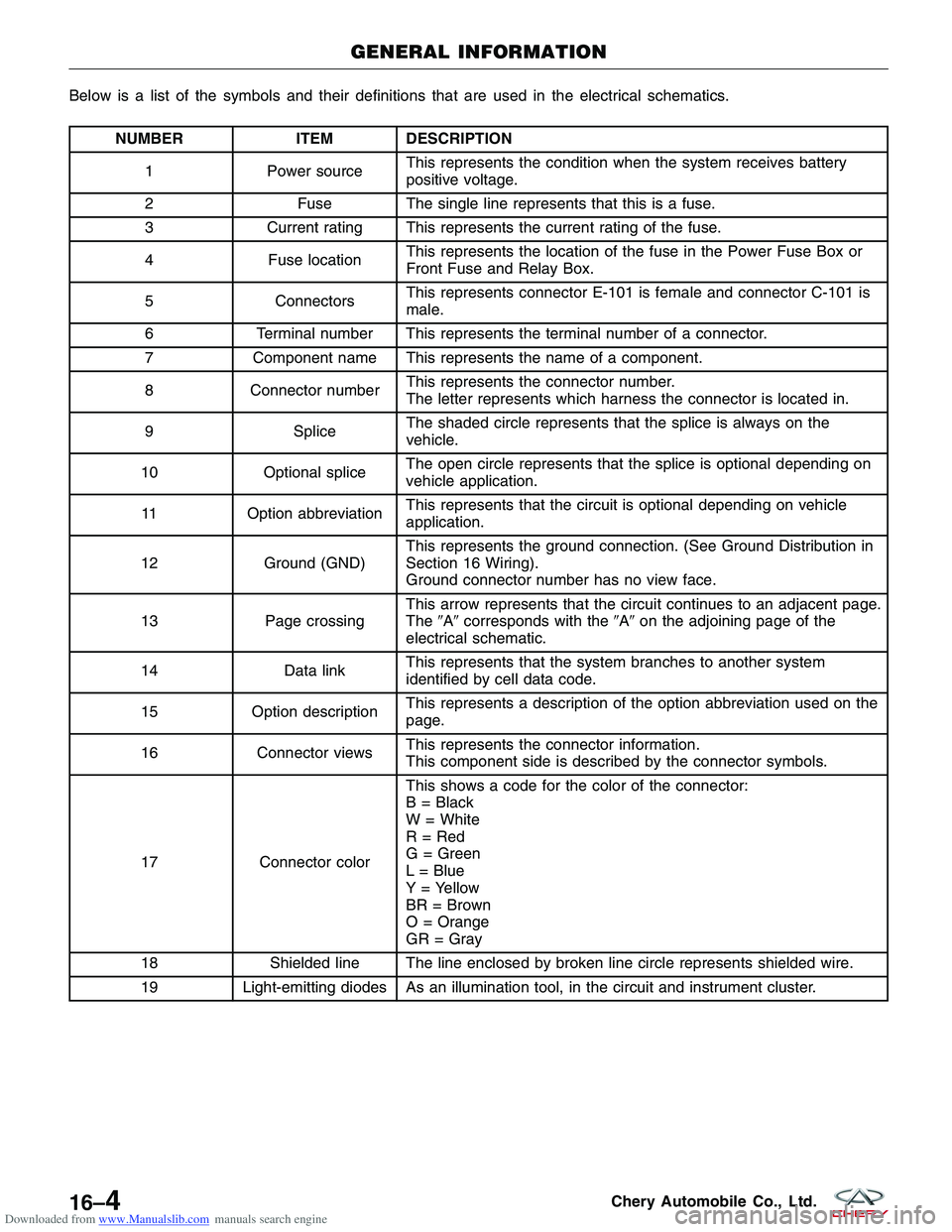
Downloaded from www.Manualslib.com manuals search engine NUMBERITEM DESCRIPTION
1 Power source This represents the condition when the system receives battery
positive voltage.
2 Fuse The single line represents that this is a fuse.
3 Current rating This represents the current rating of the fuse.
4 Fuse location This represents the location of the fuse in the Power Fuse Box or
Front Fuse and Relay Box.
5 Connectors This represents connector E-101 is female and connector C-101 is
male.
6 Terminal number This represents the terminal number of a connector.
7 Component name This represents the name of a component.
8 Connector number This represents the connector number.
The letter represents which harness the connector is located in.
9 SpliceThe shaded circle represents that the splice is always on the
vehicle.
10 Optional splice The open circle represents that the splice is optional depending on
vehicle application.
11 Option abbreviation This represents that the circuit is optional depending on vehicle
application.
12 Ground (GND) This represents the ground connection. (See Ground Distribution in
Section 16 Wiring).
Ground connector number has no view face.
13 Page crossing This arrow represents that the circuit continues to an adjacent page.
The
�A�corresponds with the �A�on the adjoining page of the
electrical schematic.
14 Data linkThis represents that the system branches to another system
identified by cell data code.
15 Option description This represents a description of the option abbreviation used on the
page.
16 Connector views This represents the connector information.
This component side is described by the connector symbols.
17 Connector color This shows a code for the color of the connector:
B = Black
W = White
R = Red
G = Green
L = Blue
Y = Yellow
BR = Brown
O = Orange
GR = Gray
18 Shielded line The line enclosed by broken line circle represents shielded wire.
19 Light-emitting diodes As an illumination tool, in the circuit and instrument cluster.
HOW TO READ ELECTRICAL SCHEMATICS
01–24Chery Automobile Co., Ltd.
Page 1830 of 1903

Downloaded from www.Manualslib.com manuals search engine Below is a list of the symbols and their definitions that are used in the electrical schematics.
NUMBERITEM DESCRIPTION
1 Power source This represents the condition when the system receives battery
positive voltage.
2 Fuse The single line represents that this is a fuse.
3 Current rating This represents the current rating of the fuse.
4 Fuse location This represents the location of the fuse in the Power Fuse Box or
Front Fuse and Relay Box.
5 Connectors This represents connector E-101 is female and connector C-101 is
male.
6 Terminal number This represents the terminal number of a connector.
7 Component name This represents the name of a component.
8 Connector number This represents the connector number.
The letter represents which harness the connector is located in.
9 Splice The shaded circle represents that the splice is always on the
vehicle.
10 Optional splice The open circle represents that the splice is optional depending on
vehicle application.
11 Option abbreviation This represents that the circuit is optional depending on vehicle
application.
12 Ground (GND) This represents the ground connection. (See Ground Distribution in
Section 16 Wiring).
Ground connector number has no view face.
13 Page crossing This arrow represents that the circuit continues to an adjacent page.
The
�A�corresponds with the �A�on the adjoining page of the
electrical schematic.
14 Data linkThis represents that the system branches to another system
identified by cell data code.
15 Option description This represents a description of the option abbreviation used on the
page.
16 Connector views This represents the connector information.
This component side is described by the connector symbols.
17 Connector color This shows a code for the color of the connector:
B = Black
W = White
R = Red
G = Green
L = Blue
Y = Yellow
BR = Brown
O = Orange
GR = Gray
18 Shielded line The line enclosed by broken line circle represents shielded wire.
19 Light-emitting diodes As an illumination tool, in the circuit and instrument cluster.
GENERAL INFORMATION
16–4Chery Automobile Co., Ltd.
Page 1864 of 1903

Downloaded from www.Manualslib.com manuals search engine GENERAL INFORMATION
Description
In order to ensure the normal operation of the system, every electrical system is equipped with fuses and relays. The
fuses and relays are stored in the fuse boxes.
The vehicle fuses and relays are located in the following locations:
•Power Fuse Box
• Front Fuse and Relay Box
• Body Fuse and Relay Box
Operation
When replacing a open fuse, it is important to use only a fuse having the correct amperage rating. The use of a fuse
with a rating other than indicated may result in a dangerous electrical system overload. If a properly rated fuse con-
tinues to open, it indicates a problem in the circuit that must be corrected.
Power Fuse Box
Description
The power fuse box is located on the side of the battery. All of the electrical current distributed throughout the vehicle
is directed through the power fuse box. The power fuse box houses five maxi-type bolt in fuses.
Operation
All of the current from the battery and the generator output enters the power fuse box through the cable and eyelet
that are secured with a nut to the power fuse box B(+) terminal stud located on one end of the power fuse box
housing. The power fuse box terminal stud cover is unlatched and opened to access the fuses.
16–38Chery Automobile Co., Ltd.