Page 1729 of 1903

Downloaded from www.Manualslib.com manuals search engine BODY EXTERIOR
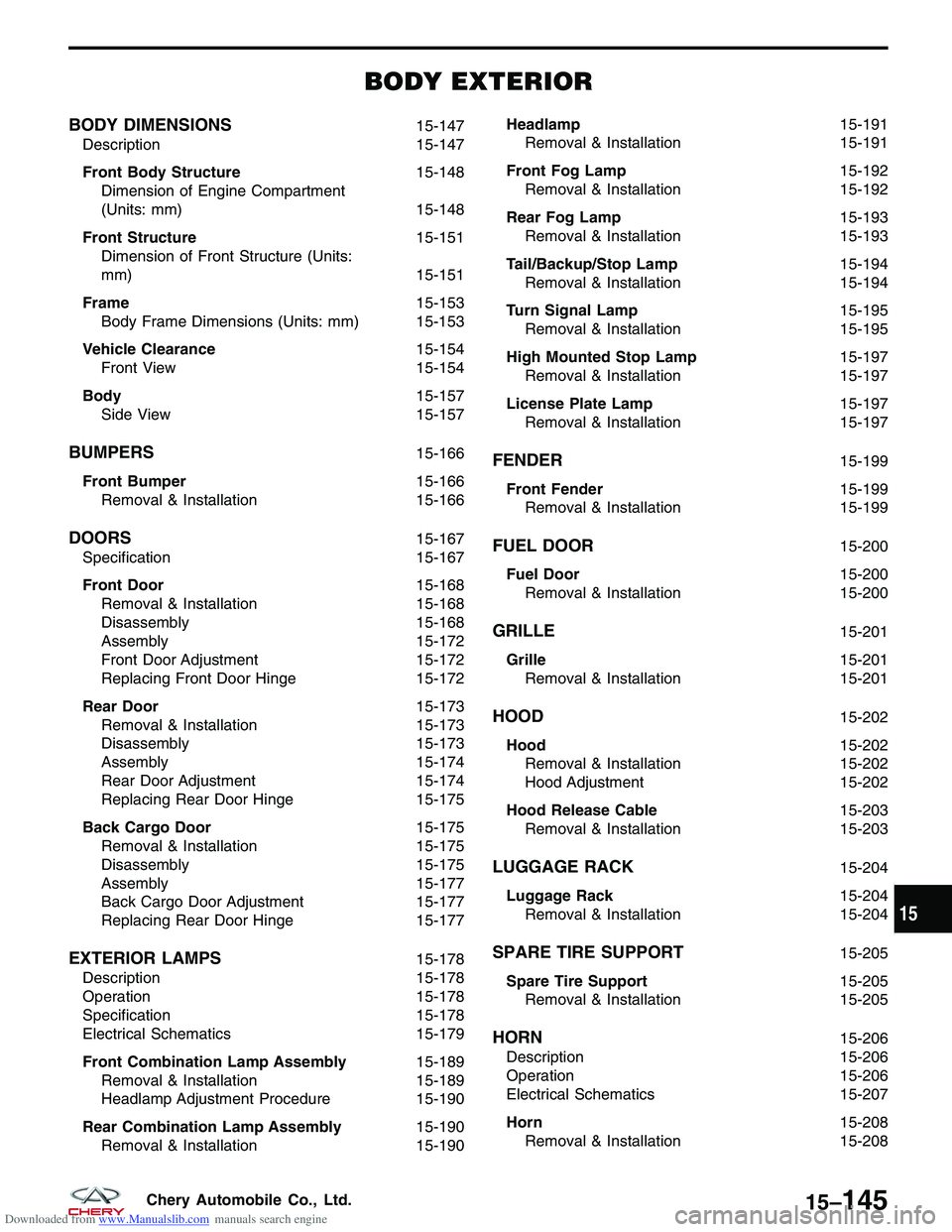
BODY DIMENSIONS15-147
Description 15-147
Front Body Structure 15-148
Dimension of Engine Compartment
(Units: mm) 15-148
Front Structure 15-151
Dimension of Front Structure (Units:
mm) 15-151
Frame 15-153
Body Frame Dimensions (Units: mm) 15-153
Vehicle Clearance 15-154
Front View 15-154
Body 15-157
Side View 15-157
BUMPERS15-166
Front Bumper 15-166
Removal & Installation 15-166
DOORS15-167
Specification 15-167
Front Door 15-168
Removal & Installation 15-168
Disassembly 15-168
Assembly 15-172
Front Door Adjustment 15-172
Replacing Front Door Hinge 15-172
Rear Door 15-173
Removal & Installation 15-173
Disassembly 15-173
Assembly 15-174
Rear Door Adjustment 15-174
Replacing Rear Door Hinge 15-175
Back Cargo Door 15-175
Removal & Installation 15-175
Disassembly 15-175
Assembly 15-177
Back Cargo Door Adjustment 15-177
Replacing Rear Door Hinge 15-177
EXTERIOR LAMPS15-178
Description 15-178
Operation 15-178
Specification 15-178
Electrical Schematics 15-179
Front Combination Lamp Assembly 15-189
Removal & Installation 15-189
Headlamp Adjustment Procedure 15-190
Rear Combination Lamp Assembly 15-190
Removal & Installation 15-190Headlamp
15-191
Removal & Installation 15-191
Front Fog Lamp 15-192
Removal & Installation 15-192
Rear Fog Lamp 15-193
Removal & Installation 15-193
Tail/Backup/Stop Lamp 15-194
Removal & Installation 15-194
Turn Signal Lamp 15-195
Removal & Installation 15-195
High Mounted Stop Lamp 15-197
Removal & Installation 15-197
License Plate Lamp 15-197
Removal & Installation 15-197
FENDER15-199
Front Fender 15-199
Removal & Installation 15-199
FUEL DOOR15-200
Fuel Door 15-200
Removal & Installation 15-200
GRILLE15-201
Grille 15-201
Removal & Installation 15-201
HOOD15-202
Hood 15-202
Removal & Installation 15-202
Hood Adjustment 15-202
Hood Release Cable 15-203
Removal & Installation 15-203
LUGGAGE RACK15-204
Luggage Rack 15-204
Removal & Installation 15-204
SPARE TIRE SUPPORT15-205
Spare Tire Support 15-205
Removal & Installation 15-205
HORN15-206
Description 15-206
Operation 15-206
Electrical Schematics 15-207
Horn 15-208
Removal & Installation 15-208
15
15–145Chery Automobile Co., Ltd.
Page 1730 of 1903

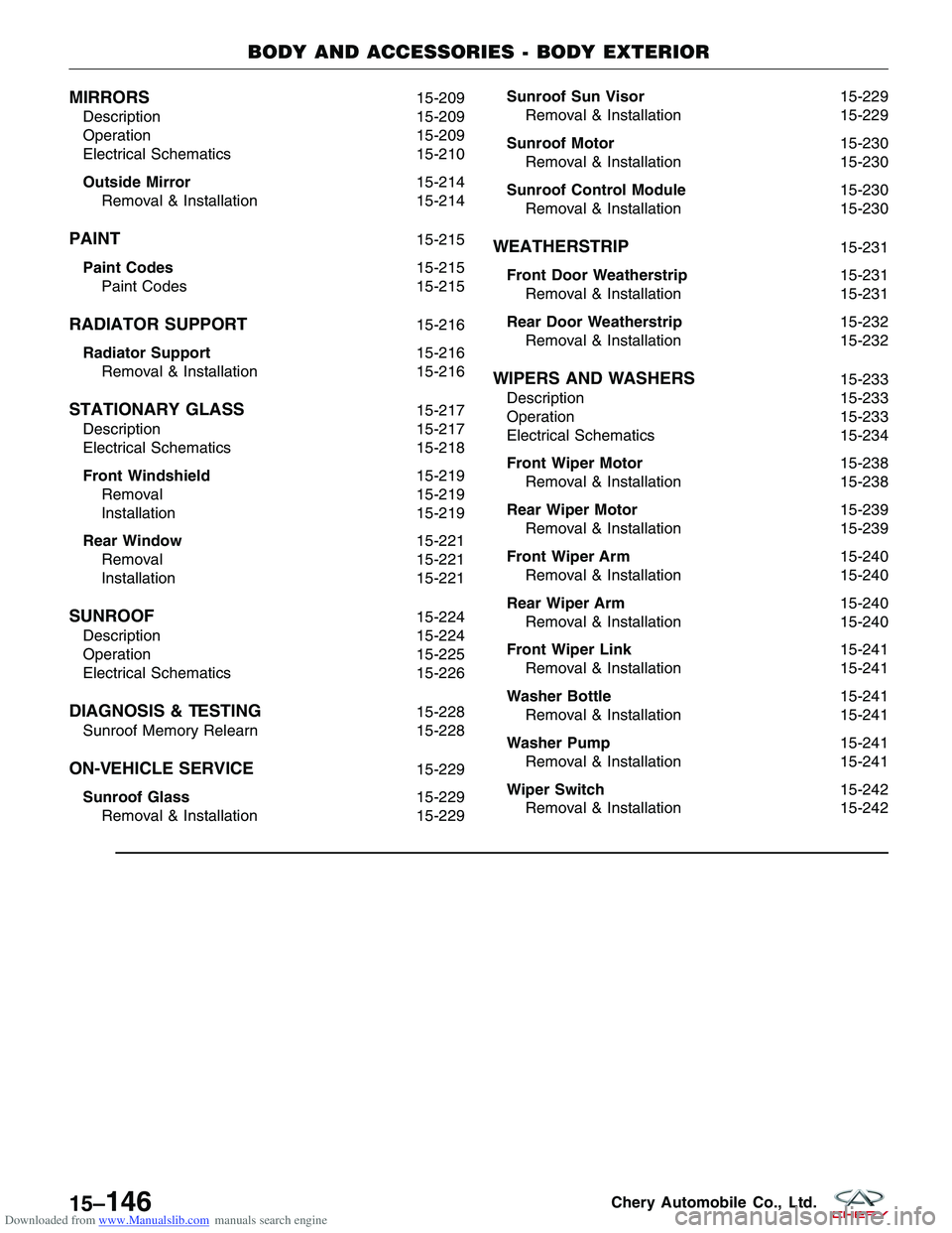
Downloaded from www.Manualslib.com manuals search engine MIRRORS15-209
Description 15-209
Operation 15-209
Electrical Schematics 15-210
Outside Mirror 15-214
Removal & Installation 15-214
PAINT15-215
Paint Codes 15-215
Paint Codes 15-215
RADIATOR SUPPORT15-216
Radiator Support 15-216
Removal & Installation 15-216
STATIONARY GLASS15-217
Description 15-217
Electrical Schematics 15-218
Front Windshield 15-219
Removal 15-219
Installation 15-219
Rear Window 15-221
Removal 15-221
Installation 15-221
SUNROOF15-224
Description 15-224
Operation 15-225
Electrical Schematics 15-226
DIAGNOSIS & TESTING15-228
Sunroof Memory Relearn 15-228
ON-VEHICLE SERVICE15-229
Sunroof Glass 15-229
Removal & Installation 15-229Sunroof Sun Visor
15-229
Removal & Installation 15-229
Sunroof Motor 15-230
Removal & Installation 15-230
Sunroof Control Module 15-230
Removal & Installation 15-230
WEATHERSTRIP15-231
Front Door Weatherstrip 15-231
Removal & Installation 15-231
Rear Door Weatherstrip 15-232
Removal & Installation 15-232
WIPERS AND WASHERS15-233
Description 15-233
Operation 15-233
Electrical Schematics 15-234
Front Wiper Motor 15-238
Removal & Installation 15-238
Rear Wiper Motor 15-239
Removal & Installation 15-239
Front Wiper Arm 15-240
Removal & Installation 15-240
Rear Wiper Arm 15-240
Removal & Installation 15-240
Front Wiper Link 15-241
Removal & Installation 15-241
Washer Bottle 15-241
Removal & Installation 15-241
Washer Pump 15-241
Removal & Installation 15-241
Wiper Switch 15-242
Removal & Installation 15-242
BODY AND ACCESSORIES - BODY EXTERIOR
15–146Chery Automobile Co., Ltd.
Page 1731 of 1903
Downloaded from www.Manualslib.com manuals search engine BODY DIMENSIONS
Description
•All measurements should be made from the bare metal, remove trim and bumper covers as necessary.
• Repair the badly damaged areas before taking measurements for underbody alignment.
• Monitor the upper body structure for excessive stress or movement while making any corrections to the under-
body structure.
• Remove all the necessary glass to prevent breakage.
• All dimensions are shown in millimeters (mm).
15
15–147Chery Automobile Co., Ltd.
Page 1732 of 1903
Downloaded from www.Manualslib.com manuals search engine Front Body Structure
Dimension of Engine Compartment (Units: mm)
BODY DIMENSIONS
LTSM150032
15–148Chery Automobile Co., Ltd.
Page 1733 of 1903
Downloaded from www.Manualslib.com manuals search engine Dimension of Body Openings
Dimension of body, Left-Right.
Uppercase letters indicate the right side of the body, lowercase letters indicate the left side of the body (Rear view).
BODY DIMENSIONS
LTSM150002
15
15–149Chery Automobile Co., Ltd.
Page 1734 of 1903
Downloaded from www.Manualslib.com manuals search engine BODY DIMENSIONS
LTSM150003
15–150Chery Automobile Co., Ltd.
Page 1735 of 1903
Downloaded from www.Manualslib.com manuals search engine Front Structure
Dimension of Front Structure (Units: mm)
Body dimension, Left-Right
BODY DIMENSIONS
LTSM150001
15
15–151Chery Automobile Co., Ltd.
Page 1736 of 1903

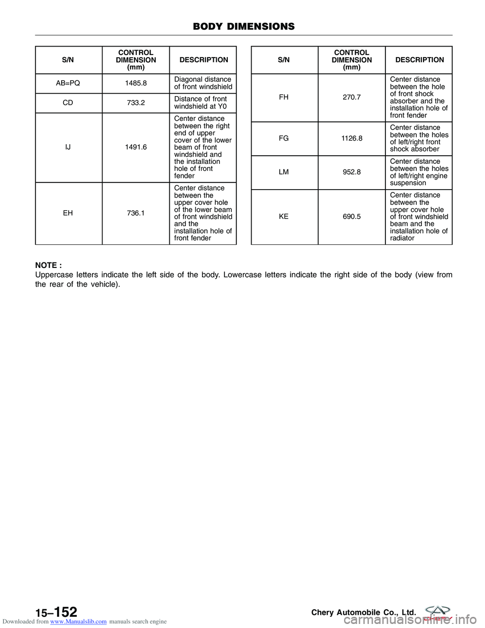
Downloaded from www.Manualslib.com manuals search engine NOTE :
Uppercase letters indicate the left side of the body. Lowercase letters indicate the right side of the body (view from
the rear of the vehicle).
S/NCONTROL
DIMENSION (mm) DESCRIPTION
AB=PQ 1485.8 Diagonal distance
of front windshield
CD 733.2Distance of front
windshield at Y0
IJ 1491.6Center distance
between the right
end of upper
cover of the lower
beam of front
windshield and
the installation
hole of front
fender
EH 736.1Center distance
between the
upper cover hole
of the lower beam
of front windshield
and the
installation hole of
front fenderS/N
CONTROL
DIMENSION (mm) DESCRIPTION
FH 270.7 Center distance
between the hole
of front shock
absorber and the
installation hole of
front fender
FG 1126.8Center distance
between the holes
of left/right front
shock absorber
LM 952.8Center distance
between the holes
of left/right engine
suspension
KE 690.5Center distance
between the
upper cover hole
of front windshield
beam and the
installation hole of
radiator
BODY DIMENSIONS
LTSM150001
15–152Chery Automobile Co., Ltd.