2008 NISSAN TEANA fuse
[x] Cancel search: fusePage 4253 of 5121
SRC-10
< FUNCTION DIAGNOSIS >
DIAGNOSIS SYSTEM (AIRBAG)
DIAGNOSIS SYSTEM (AIRBAG)
Diagnosis DescriptionINFOID:0000000003813934
CAUTION:
• Never use electrical test equipment on any circuit related to the SRS unless instructed in this Ser-
vice Manual. SRS wiring harnesses can be identified by yellow and/or orange harnesses or harness
connectors.
Never repair, splice or modify the SRS wiring harness. If the harness is damaged, replace it with a
new one.
Keep ground portion clean.
DIAGNOSIS FUNCTION
The SRS self-diagnosis results can be read by using air bag warning lamp and/or CONSULT-III.
The user mode is exclusively prepared for the customer (driver). This mode warns the driver of a system
malfunction through the operation of the air bag warning lamp.
The diagnosis mode allows the technician to locate and inspect the malfunctioning part.
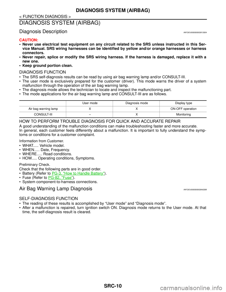
The mode applications for the air bag warning lamp and CONSULT-III are as follows.
HOW TO PERFORM TROUBLE DIAGNOSIS FOR QUICK AND ACCURATE REPAIR
A good understanding of the malfunction conditions can make troubleshooting faster and more accurate.
In general, each customer feels differently about a malfunction. It is important to fully understand the symp-
toms or conditions for a customer complaint.
Information from Customer.
WHAT..... Vehicle model.
WHEN..... Date, Frequency.
WHERE..... Road conditions.
HOW..... Operating conditions, Symptoms.
Preliminary Check.
Check that the following parts are in good order.
Battery (Refer to PG-3, "
How to Handle Battery").
Fuse (Refer to PG-82, "
Fuse").
System component-to-harness connections.
Air Bag Warning Lamp DiagnosisINFOID:0000000003843289
SELF-DIAGNOSIS FUNCTION
The reading of these results is accomplished by “User mode” and “Diagnosis mode”.
After a malfunction is repaired, turn ignition switch ON. Diagnosis mode returns to the User mode. At that
time, the self-diagnosis result is cleared.
User mode Diagnosis mode Display type
Air bag warning lamp X X ON-OFF operation
CONSULT-III – X Monitoring
Page 4388 of 5121
SRS AIR BAG WARNING LAMP DOES NOT TURN OFF
SRC-145
< SYMPTOM DIAGNOSIS >
C
D
E
F
G
I
J
K
L
MA
B
SRC
N
O
P
SYMPTOM DIAGNOSIS
SRS AIR BAG WARNING LAMP DOES NOT TURN OFF
Diagnosis ProcedureINFOID:0000000003814106
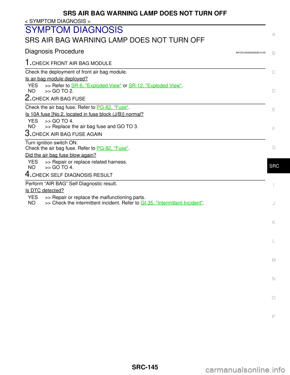
1.CHECK FRONT AIR BAG MODULE
Check the deployment of front air bag module.
Is air bag module deployed?
YES >> Refer to SR-6, "Exploded View" or SR-12, "Exploded View".
NO >> GO TO 2.
2.CHECK AIR BAG FUSE
Check the air bag fuse. Refer to PG-82, "
Fuse".
Is 10A fuse [No.2, located in fuse block (J/B)] normal?
YES >> GO TO 4.
NO >> Replace the air bag fuse and GO TO 3.
3.CHECK AIR BAG FUSE AGAIN
Turn ignition switch ON.
Check the air bag fuse. Refer to PG-82, "
Fuse".
Did the air bag fuse blow again?
YES >> Repair or replace related harness.
NO >> GO TO 4.
4.CHECK SELF DIAGNOSIS RESULT
Perform “AIR BAG” Self Diagnostic result.
Is DTC detected?
YES >> Repair or replace the malfunctioning parts.
NO >> Check the intermittent incident. Refer to GI-35, "
Intermittent Incident".
Page 4389 of 5121
SRC-146
< SYMPTOM DIAGNOSIS >
SRS AIR BAG WARNING LAMP DOES NOT TURN ON
SRS AIR BAG WARNING LAMP DOES NOT TURN ON
Diagnosis ProcedureINFOID:0000000003814107
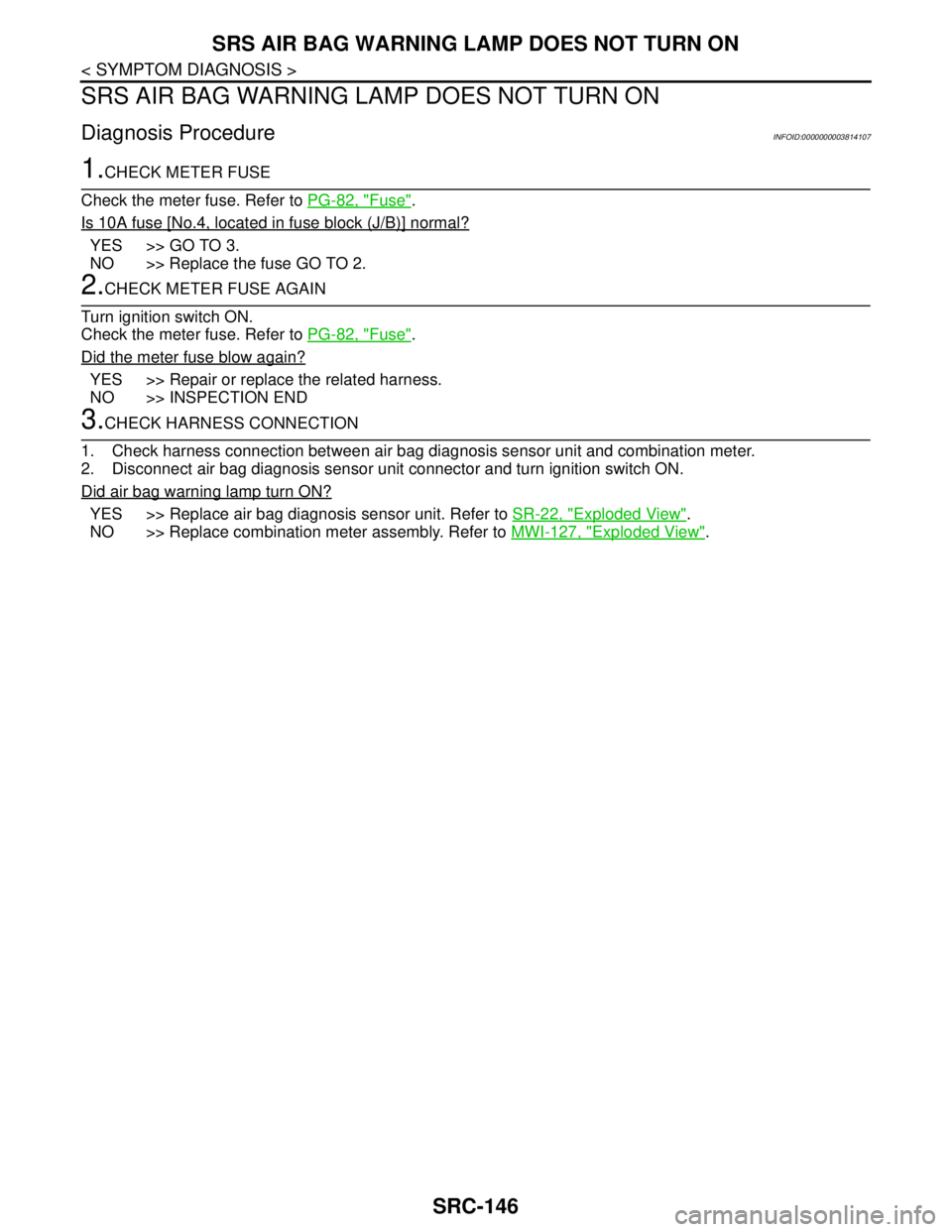
1.CHECK METER FUSE
Check the meter fuse. Refer to PG-82, "
Fuse".
Is 10A fuse [No.4, located in fuse block (J/B)] normal?
YES >> GO TO 3.
NO >> Replace the fuse GO TO 2.
2.CHECK METER FUSE AGAIN
Turn ignition switch ON.
Check the meter fuse. Refer to PG-82, "
Fuse".
Did the meter fuse blow again?
YES >> Repair or replace the related harness.
NO >> INSPECTION END
3.CHECK HARNESS CONNECTION
1. Check harness connection between air bag diagnosis sensor unit and combination meter.
2. Disconnect air bag diagnosis sensor unit connector and turn ignition switch ON.
Did air bag warning lamp turn ON?
YES >> Replace air bag diagnosis sensor unit. Refer to SR-22, "Exploded View".
NO >> Replace combination meter assembly. Refer to MWI-127, "
Exploded View".
Page 4397 of 5121
POWER STEERING FLUID
ST-7
< ON-VEHICLE MAINTENANCE >
C
D
E
F
H
I
J
K
L
MA
B
ST
N
O
P
ON-VEHICLE MAINTENANCE
POWER STEERING FLUID
InspectionINFOID:0000000003826225
FLUID LEVEL
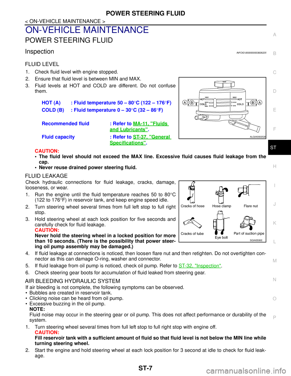
1. Check fluid level with engine stopped.
2. Ensure that fluid level is between MIN and MAX.
3. Fluid levels at HOT and COLD are different. Do not confuse
them.
CAUTION:
The fluid level should not exceed the MAX line. Excessive fluid causes fluid leakage from the
cap.
Never reuse drained power steering fluid.
FLUID LEAKAGE
Check hydraulic connections for fluid leakage, cracks, damage,
looseness, or wear.
1. Run the engine until the fluid temperature reaches 50 to 80°C
(122 to 176°F) in reservoir tank, and keep engine speed idle.
2. Turn steering wheel several times from full left stop to full right
stop.
3. Hold steering wheel at each lock position for five seconds and
carefully check for fluid leakage.
CAUTION:
Never hold the steering wheel in a locked position for more
than 10 seconds. (There is the possibility that power steer-
ing oil pump assembly may be damaged.)
4. If fluid leakage at connections is noticed, then loosen flare nut and then retighten. Do not overtighten con-
nector as this can damage O-ring, washer and connector.
5. If fluid leakage from oil pump is noticed, check oil pump. Refer to ST-32, "
Inspection".
6. Check steering gear boots for accumulation of fluid leaked from steering gear.
AIR BLEEDING HYDRAULIC SYSTEM
If air bleeding is not complete, the following symptoms can be observed.
Bubbles are created in reservoir tank.
Clicking noise can be heard from oil pump.
Excessive buzzing in the oil pump.
NOTE:
Fluid noise may occur in the steering gear or oil pump. This does not affect performance or durability of the
system.
1. Turn steering wheel several times from full left stop to full right stop with engine off.
CAUTION:
Fill reservoir tank with a sufficient amount of fluid so that fluid level is not below the MIN line while
turning steering wheel.
2. Start the engine and hold steering wheel at each lock position for 3 second at idle to check for fluid leak-
age.HOT (A) : Fluid temperature 50 – 80°C (122 – 176°F)
COLD (B) : Fluid temperature 0 – 30°C (32 – 86°F)
Recommended fluid : Refer to MA-11, "
Fluids
and Lubricants".
Fluid capacity : Refer to ST-37, "
General
Specifications".
ALGIA0002GB
SGIA0506E
Page 4434 of 5121
STC-6
< COMPONENT DIAGNOSIS >
POWER SUPPLY AND GROUND CIRCUIT
COMPONENT DIAGNOSIS
POWER SUPPLY AND GROUND CIRCUIT
DescriptionINFOID:0000000003893526
Power supply to EPS system
Diagnosis ProcedureINFOID:0000000003893527
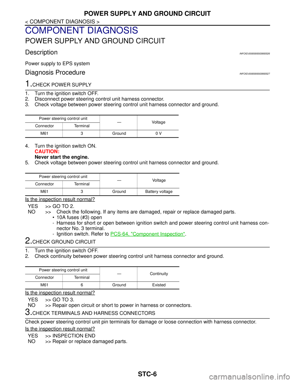
1.CHECK POWER SUPPLY
1. Turn the ignition switch OFF.
2. Disconnect power steering control unit harness connector.
3. Check voltage between power steering control unit harness connector and ground.
4. Turn the ignition switch ON.
CAUTION:
Never start the engine.
5. Check voltage between power steering control unit harness connector and ground.
Is the inspection result normal?
YES >> GO TO 2.
NO >> Check the following. If any items are damaged, repair or replace damaged parts.
10A fuses (#3) open
- Harness for short or open between ignition switch and power steering control unit harness con-
nector No. 3 terminal.
- Ignition switch. Refer to PCS-64, "
Component Inspection".
2.CHECK GROUND CIRCUIT
1. Turn the ignition switch OFF.
2. Check continuity between power steering control unit harness connector and ground.
Is the inspection result normal?
YES >> GO TO 3.
NO >> Repair open circuit or short to power in harness or connectors.
3.CHECK TERMINALS AND HARNESS CONNECTORS
Check power steering control unit pin terminals for damage or loose connection with harness connector.
Is the inspection result normal?
YES >> INSPECTION END
NO >> Repair or replace damaged parts.
Power steering control unit
—Voltage
Connector Terminal
M61 3 Ground 0 V
Power steering control unit
— Voltage
Connector Terminal
M61 3 Ground Battery voltage
Power steering control unit
—Continuity
Connector Terminal
M61 6 Ground Existed
Page 4450 of 5121
DIAGNOSIS AND REPAIR WORKFLOW
STR-3
< BASIC INSPECTION >
C
D
E
F
G
H
I
J
K
L
MA
STR
N
P O
NOTE:
If any malfunction is found, immediately disconnect the battery cable from the negative terminal.
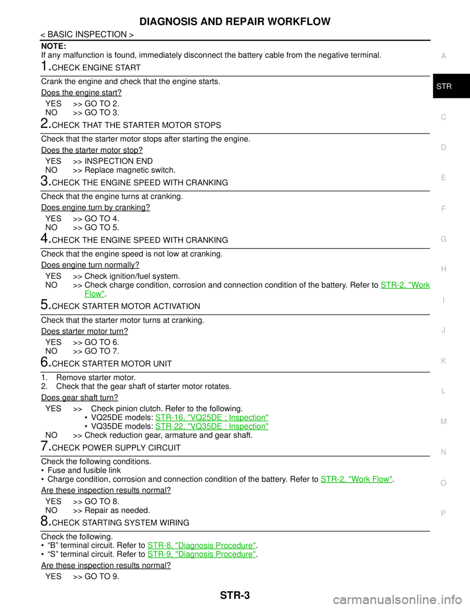
1.CHECK ENGINE START
Crank the engine and check that the engine starts.
Does the engine start?
YES >> GO TO 2.
NO >> GO TO 3.
2.CHECK THAT THE STARTER MOTOR STOPS
Check that the starter motor stops after starting the engine.
Does the starter motor stop?
YES >> INSPECTION END
NO >> Replace magnetic switch.
3.CHECK THE ENGINE SPEED WITH CRANKING
Check that the engine turns at cranking.
Does engine turn by cranking?
YES >> GO TO 4.
NO >> GO TO 5.
4.CHECK THE ENGINE SPEED WITH CRANKING
Check that the engine speed is not low at cranking.
Does engine turn normally?
YES >> Check ignition/fuel system.
NO >> Check charge condition, corrosion and connection condition of the battery. Refer to STR-2, "
Work
Flow".
5.CHECK STARTER MOTOR ACTIVATION
Check that the starter motor turns at cranking.
Does starter motor turn?
YES >> GO TO 6.
NO >> GO TO 7.
6.CHECK STARTER MOTOR UNIT
1. Remove starter motor.
2. Check that the gear shaft of starter motor rotates.
Does gear shaft turn?
YES >> Check pinion clutch. Refer to the following.
• VQ25DE models: STR-16, "
VQ25DE : Inspection"
VQ35DE models: STR-22, "VQ35DE : Inspection"
NO >> Check reduction gear, armature and gear shaft.
7.CHECK POWER SUPPLY CIRCUIT
Check the following conditions.
Fuse and fusible link
Charge condition, corrosion and connection condition of the battery. Refer to STR-2, "
Work Flow".
Are these inspection results normal?
YES >> GO TO 8.
NO >> Repair as needed.
8.CHECK STARTING SYSTEM WIRING
Check the following.
“B” terminal circuit. Refer to STR-8, "
Diagnosis Procedure".
“S” terminal circuit. Refer to STR-9, "
Diagnosis Procedure".
Are these inspection results normal?
YES >> GO TO 9.
Page 4455 of 5121
STR-8
< COMPONENT DIAGNOSIS >
B TERMINAL CIRCUIT
COMPONENT DIAGNOSIS
B TERMINAL CIRCUIT
DescriptionINFOID:0000000003860425
The “B” terminal is constantly supplied with battery power.
Diagnosis ProcedureINFOID:0000000003860426
CAUTION:
Perform diagnosis under the condition that engine cannot start by the following procedure.
1. Remove fuel pump fuse.
2. Crank or start the engine (where possible) until the fuel pressure is released.
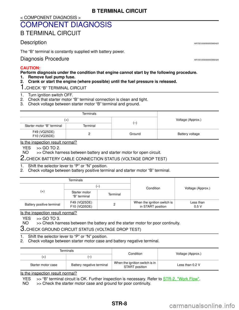
1.CHECK “B” TERMINAL CIRCUIT
1. Turn ignition switch OFF.
2. Check that starter motor “B” terminal connection is clean and tight.
3. Check voltage between starter motor “B” terminal and ground.
Is the inspection result normal?
YES >> GO TO 2.
NO >> Check harness between battery and starter motor for open circuit.
2.CHECK BATTERY CABLE CONNECTION STATUS (VOLTAGE DROP TEST)
1. Shift the selector lever to “P” or “N” position.
2. Check voltage between battery positive terminal and starter motor “B” terminal.
Is the inspection result normal?
YES >> GO TO 3.
NO >> Check harness between the battery and the starter motor for poor continuity.
3.CHECK GROUND CIRCUIT STATUS (VOLTAGE DROP TEST)
1. Shift the selector lever to “P” or “N” position.
2. Check voltage between starter motor case and battery negative terminal.
Is the inspection result normal?
YES >> “B” terminal circuit is OK. Further inspection is necessary. Refer to STR-2, "Work Flow".
NO >> Check the starter motor case and ground for poor continuity.
Te r m i n a l s
Voltage (Approx.) (+)
(–)
Starter motor “B” terminal Terminal
F49 (VQ25DE)
F10 (VQ35DE)2 Ground Battery voltage
Te r m i n a l s
Condition Voltage (Approx.)
(+)(–)
Starter motor
“B” terminalTerminal
Battery positive terminalF49 (VQ25DE)
F10 (VQ35DE)2 When the ignition switch is
in START positionLess than
0.5 V
Te r m i n a l s
Condition Voltage (Approx.)
(+) (–)
Starter motor case Battery negative terminalWhen the ignition switch is in
START positionLess than 0.2 V
Page 4456 of 5121
S TERMINAL CIRCUIT
STR-9
< COMPONENT DIAGNOSIS >
C
D
E
F
G
H
I
J
K
L
MA
STR
N
P O
S TERMINAL CIRCUIT
DescriptionINFOID:0000000003860427
The starter motor magnetic switch is supplied with power when the ignition switch is turned to START with the
selector lever “P” or “N”.
Diagnosis ProcedureINFOID:0000000003860428
CAUTION:
Perform diagnosis under the condition that engine cannot start by the following procedure.
1. Remove fuel pump fuse.
2. Crank or start the engine (where possible) until the fuel pressure is released.
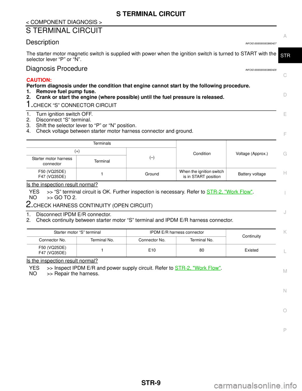
1.CHECK “S” CONNECTOR CIRCUIT
1. Turn ignition switch OFF.
2. Disconnect “S” terminal.
3. Shift the selector lever to “P” or “N” position.
4. Check voltage between starter motor harness connector and ground.
Is the inspection result normal?
YES >> “S” terminal circuit is OK. Further inspection is necessary. Refer to STR-2, "Work Flow".
NO >> GO TO 2.
2.CHECK HARNESS CONTINUITY (OPEN CIRCUIT)
1. Disconnect IPDM E/R connector.
2. Check continuity between starter motor “S” terminal and IPDM E/R harness connector.
Is the inspection result normal?
YES >> Inspect IPDM E/R and power supply circuit. Refer to STR-2, "Work Flow".
NO >> Repair the harness.
Te r m i n a l s
Condition Voltage (Approx.) (+)
(–)
Starter motor harness
connectorTe r m i n a l
F50 (VQ25DE)
F47 (VQ35DE)1 GroundWhen the ignition switch
is in START positionBattery voltage
Starter motor “S” terminal IPDM E/R harness connector
Continuity
Connector No. Terminal No. Connector No. Terminal No.
F50 (VQ25DE)
F47 (VQ35DE)1E1080Existed