2008 NISSAN TEANA fuse
[x] Cancel search: fusePage 3763 of 5121
RF-32
< ECU DIAGNOSIS >
BCM (BODY CONTROL MODULE)
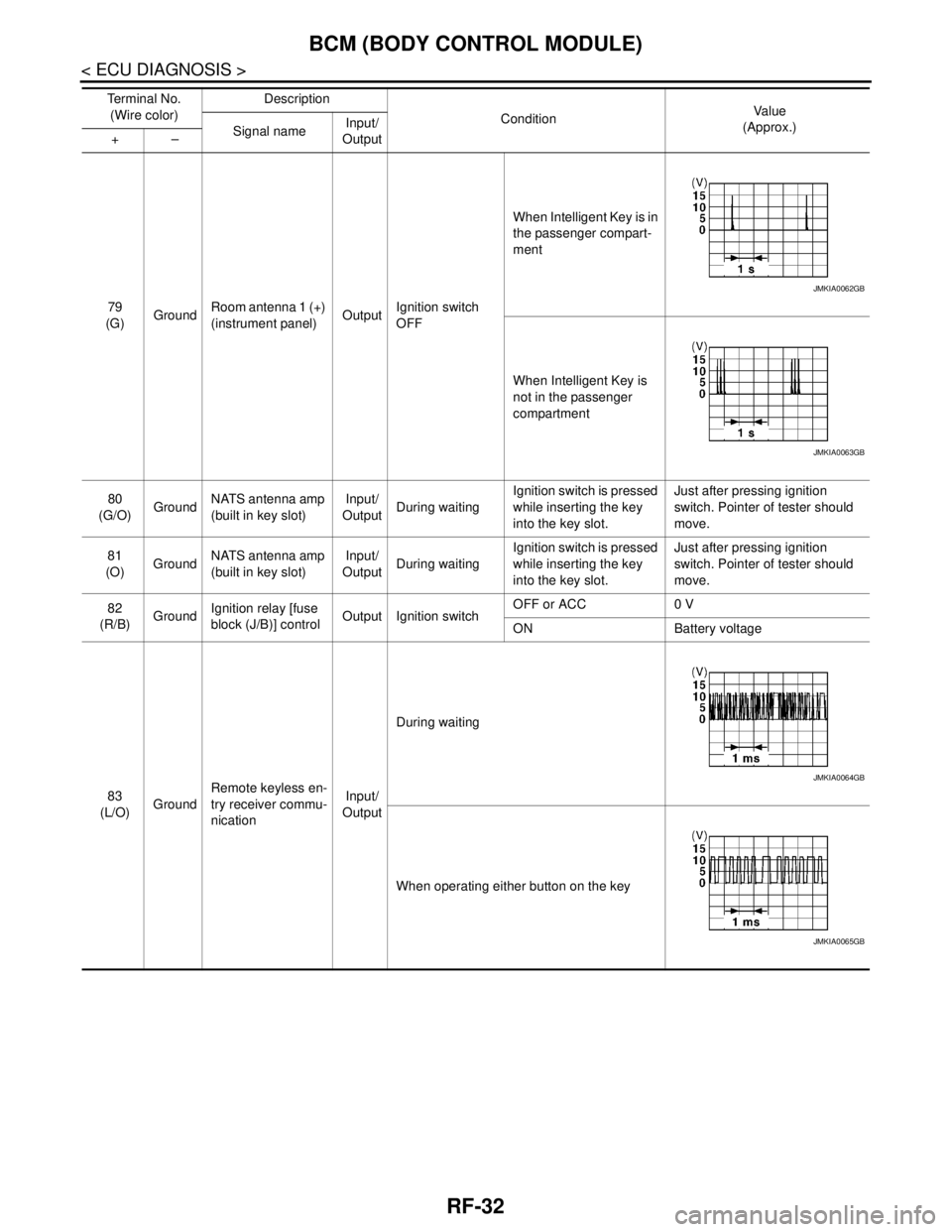
79
(G)GroundRoom antenna 1 (+)
(instrument panel)OutputIgnition switch
OFFWhen Intelligent Key is in
the passenger compart-
ment
When Intelligent Key is
not in the passenger
compartment
80
(G/O)GroundNATS antenna amp
(built in key slot)Input/
OutputDuring waitingIgnition switch is pressed
while inserting the key
into the key slot.Just after pressing ignition
switch. Pointer of tester should
move.
81
(O)GroundNATS antenna amp
(built in key slot)Input/
OutputDuring waitingIgnition switch is pressed
while inserting the key
into the key slot.Just after pressing ignition
switch. Pointer of tester should
move.
82
(R/B)GroundIgnition relay [fuse
block (J/B)] controlOutput Ignition switchOFF or ACC 0 V
ON Battery voltage
83
(L/O)GroundRemote keyless en-
try receiver commu-
nicationInput/
OutputDuring waiting
When operating either button on the key Te r m i n a l N o .
(Wire color)Description
ConditionVa l u e
(Approx.)
Signal nameInput/
Output +–
JMKIA0062GB
JMKIA0063GB
JMKIA0064GB
JMKIA0065GB
Page 3770 of 5121
BCM (BODY CONTROL MODULE)
RF-39
< ECU DIAGNOSIS >
C
D
E
F
G
H
I
J
L
MA
B
RF
N
O
P
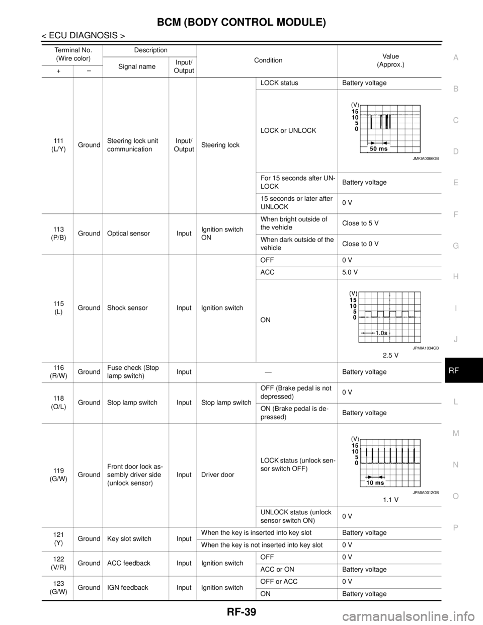
111
(L/Y)GroundSteering lock unit
communicationInput/
OutputSteering lockLOCK status Battery voltage
LOCK or UNLOCK
For 15 seconds after UN-
LOCKBattery voltage
15 seconds or later after
UNLOCK0 V
11 3
(P/B)Ground Optical sensor InputIgnition switch
ONWhen bright outside of
the vehicleClose to 5 V
When dark outside of the
vehicleClose to 0 V
11 5
(L)Ground Shock sensor Input Ignition switchOFF 0 V
ACC 5.0 V
ON
2.5 V
11 6
(R/W)GroundFuse check (Stop
lamp switch)Input — Battery voltage
11 8
(O/L)Ground Stop lamp switch Input Stop lamp switchOFF (Brake pedal is not
depressed)0 V
ON (Brake pedal is de-
pressed)Battery voltage
11 9
(G/W)GroundFront door lock as-
sembly driver side
(unlock sensor)Input Driver doorLOCK status (unlock sen-
sor switch OFF)
1.1 V
UNLOCK status (unlock
sensor switch ON)0 V
121
(Y)Ground Key slot switch InputWhen the key is inserted into key slot Battery voltage
When the key is not inserted into key slot 0 V
122
(V/R)Ground ACC feedback Input Ignition switchOFF 0 V
ACC or ON Battery voltage
123
(G/W)Ground IGN feedback Input Ignition switchOFF or ACC 0 V
ON Battery voltage Te r m i n a l N o .
(Wire color)Description
ConditionVa l u e
(Approx.)
Signal nameInput/
Output +–
JMKIA0066GB
JPMIA1034GB
JPMIA0012GB
Page 3821 of 5121
RF-90
< ON-VEHICLE REPAIR >
SUNROOF UNIT ASSEMBLY
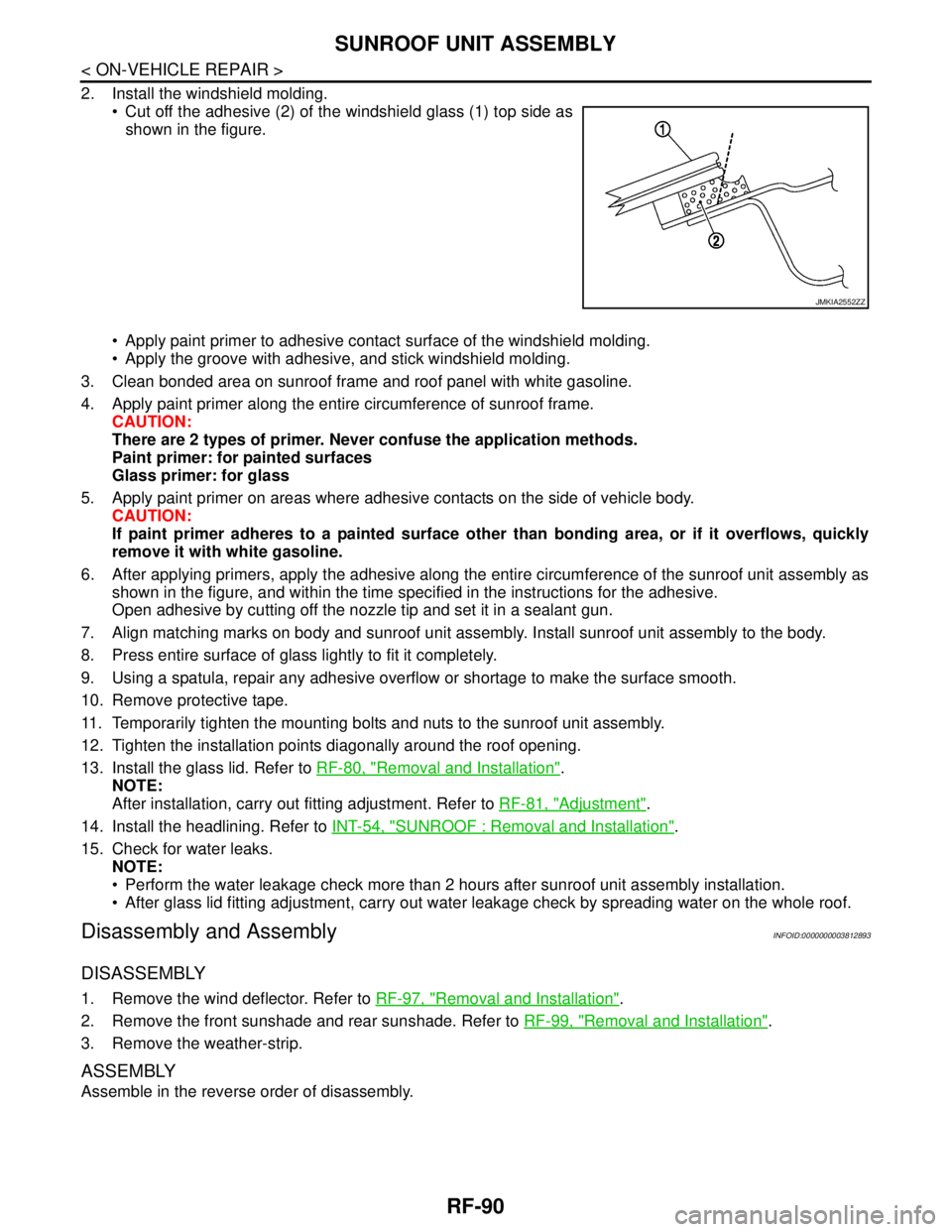
2. Install the windshield molding.
Cut off the adhesive (2) of the windshield glass (1) top side as
shown in the figure.
Apply paint primer to adhesive contact surface of the windshield molding.
Apply the groove with adhesive, and stick windshield molding.
3. Clean bonded area on sunroof frame and roof panel with white gasoline.
4. Apply paint primer along the entire circumference of sunroof frame.
CAUTION:
There are 2 types of primer. Never confuse the application methods.
Paint primer: for painted surfaces
Glass primer: for glass
5. Apply paint primer on areas where adhesive contacts on the side of vehicle body.
CAUTION:
If paint primer adheres to a painted surface other than bonding area, or if it overflows, quickly
remove it with white gasoline.
6. After applying primers, apply the adhesive along the entire circumference of the sunroof unit assembly as
shown in the figure, and within the time specified in the instructions for the adhesive.
Open adhesive by cutting off the nozzle tip and set it in a sealant gun.
7. Align matching marks on body and sunroof unit assembly. Install sunroof unit assembly to the body.
8. Press entire surface of glass lightly to fit it completely.
9. Using a spatula, repair any adhesive overflow or shortage to make the surface smooth.
10. Remove protective tape.
11. Temporarily tighten the mounting bolts and nuts to the sunroof unit assembly.
12. Tighten the installation points diagonally around the roof opening.
13. Install the glass lid. Refer to RF-80, "
Removal and Installation".
NOTE:
After installation, carry out fitting adjustment. Refer to RF-81, "
Adjustment".
14. Install the headlining. Refer to INT-54, "
SUNROOF : Removal and Installation".
15. Check for water leaks.
NOTE:
Perform the water leakage check more than 2 hours after sunroof unit assembly installation.
After glass lid fitting adjustment, carry out water leakage check by spreading water on the whole roof.
Disassembly and AssemblyINFOID:0000000003812893
DISASSEMBLY
1. Remove the wind deflector. Refer to RF-97, "Removal and Installation".
2. Remove the front sunshade and rear sunshade. Refer to RF-99, "
Removal and Installation".
3. Remove the weather-strip.
ASSEMBLY
Assemble in the reverse order of disassembly.
JMKIA2552ZZ
Page 3823 of 5121
RF-92
< ON-VEHICLE REPAIR >
FRONT SUNROOF GLASS
5. Apply protective tape around the roof panel and windshield to protect the surface from damage.
6. Remove weather-strip.
7. Cut adhesive.
Pass piano wire though the adhesive with a wire pierce.
Tie both ends of piano wire to wire grip.
Pull piano wire in turn and cut off adhesive.
8. Remove front sunroof glass from vehicle.
WARNING:
Always use safety glasses and heavy gloves to help prevent glass splinters from entering your eyes
or cutting your hands when cutting the glass from the vehicle.
CAUTION:
Never reuse the front sunroof glass which has been removed once.
INSTALLATION
WARNING:
Keep heat and open flames away as primers and adhesive are flammable.
The materials contained in the kit are harmful if swallowed, and may irritate skin and eyes. Never let
them in contact with the skin and eyes.
Use in an open, well ventilated location. Never breathe the vapors. They may be harmful if inhaled.
Move immediately to an area with fresh air if affected by vapor inhalation.
NOTE:
Use a genuine Nissan Urethane Adhesive Kit (if available) or an equivalent and follow the instructions fur-
nished with it.
Inform the customer that the vehicle should remain stationary until the urethane adhesive has completely
cured (approximately 24 hours). Curing time varies with temperature and humidity.
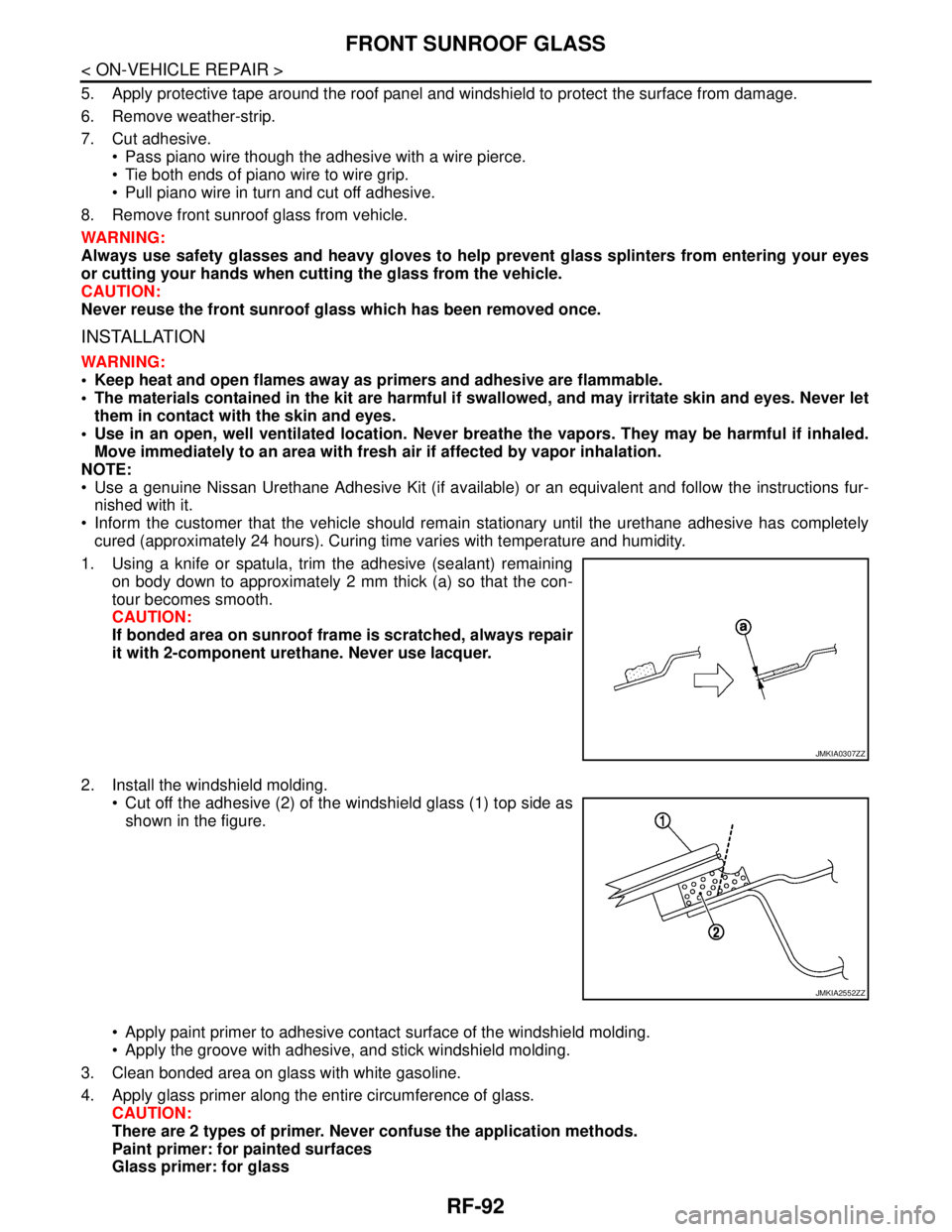
1. Using a knife or spatula, trim the adhesive (sealant) remaining
on body down to approximately 2 mm thick (a) so that the con-
tour becomes smooth.
CAUTION:
If bonded area on sunroof frame is scratched, always repair
it with 2-component urethane. Never use lacquer.
2. Install the windshield molding.
Cut off the adhesive (2) of the windshield glass (1) top side as
shown in the figure.
Apply paint primer to adhesive contact surface of the windshield molding.
Apply the groove with adhesive, and stick windshield molding.
3. Clean bonded area on glass with white gasoline.
4. Apply glass primer along the entire circumference of glass.
CAUTION:
There are 2 types of primer. Never confuse the application methods.
Paint primer: for painted surfaces
Glass primer: for glass
JMKIA0307ZZ
JMKIA2552ZZ
Page 3826 of 5121
REAR SUNROOF GLASS
RF-95
< ON-VEHICLE REPAIR >
C
D
E
F
G
H
I
J
L
MA
B
RF
N
O
P
5. Remove weather-strip.
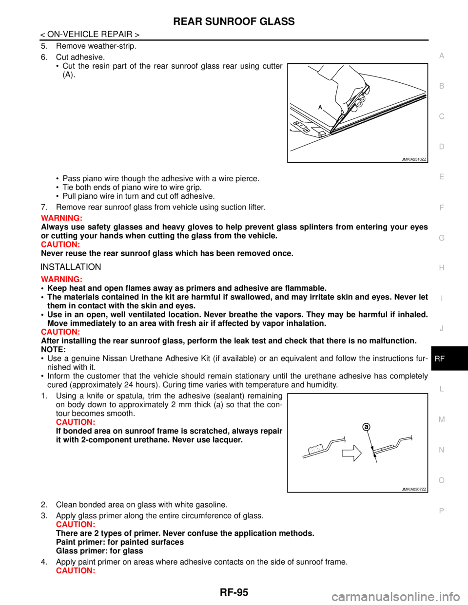
6. Cut adhesive.
Cut the resin part of the rear sunroof glass rear using cutter
(A).
Pass piano wire though the adhesive with a wire pierce.
Tie both ends of piano wire to wire grip.
Pull piano wire in turn and cut off adhesive.
7. Remove rear sunroof glass from vehicle using suction lifter.
WARNING:
Always use safety glasses and heavy gloves to help prevent glass splinters from entering your eyes
or cutting your hands when cutting the glass from the vehicle.
CAUTION:
Never reuse the rear sunroof glass which has been removed once.
INSTALLATION
WARNING:
Keep heat and open flames away as primers and adhesive are flammable.
The materials contained in the kit are harmful if swallowed, and may irritate skin and eyes. Never let
them in contact with the skin and eyes.
Use in an open, well ventilated location. Never breathe the vapors. They may be harmful if inhaled.
Move immediately to an area with fresh air if affected by vapor inhalation.
CAUTION:
After installing the rear sunroof glass, perform the leak test and check that there is no malfunction.
NOTE:
Use a genuine Nissan Urethane Adhesive Kit (if available) or an equivalent and follow the instructions fur-
nished with it.
Inform the customer that the vehicle should remain stationary until the urethane adhesive has completely
cured (approximately 24 hours). Curing time varies with temperature and humidity.
1. Using a knife or spatula, trim the adhesive (sealant) remaining
on body down to approximately 2 mm thick (a) so that the con-
tour becomes smooth.
CAUTION:
If bonded area on sunroof frame is scratched, always repair
it with 2-component urethane. Never use lacquer.
2. Clean bonded area on glass with white gasoline.
3. Apply glass primer along the entire circumference of glass.
CAUTION:
There are 2 types of primer. Never confuse the application methods.
Paint primer: for painted surfaces
Glass primer: for glass
4. Apply paint primer on areas where adhesive contacts on the side of sunroof frame.
CAUTION:
JMKIA2510ZZ
JMKIA0307ZZ
Page 3876 of 5121
![NISSAN TEANA 2008 Service Manual SE-12
< COMPONENT DIAGNOSIS >[WITH VENTILATION SEAT]
POWER SUPPLY AND GROUND CIRCUIT
COMPONENT DIAGNOSIS
POWER SUPPLY AND GROUND CIRCUIT
VENTILATION SEAT CONTROL UNIT
VENTILATION SEAT CONTROL UNIT : D NISSAN TEANA 2008 Service Manual SE-12
< COMPONENT DIAGNOSIS >[WITH VENTILATION SEAT]
POWER SUPPLY AND GROUND CIRCUIT
COMPONENT DIAGNOSIS
POWER SUPPLY AND GROUND CIRCUIT
VENTILATION SEAT CONTROL UNIT
VENTILATION SEAT CONTROL UNIT : D](/manual-img/5/57391/w960_57391-3875.png)
SE-12
< COMPONENT DIAGNOSIS >[WITH VENTILATION SEAT]
POWER SUPPLY AND GROUND CIRCUIT
COMPONENT DIAGNOSIS
POWER SUPPLY AND GROUND CIRCUIT
VENTILATION SEAT CONTROL UNIT
VENTILATION SEAT CONTROL UNIT : Diagnosis ProcedureINFOID:0000000003809329
1.CHECK FUSE
Check that the following fuses are not fusing.
Is the fuse fusing?
YES >> Replace the blown fuse after repairing the affected circuit if a fuse is blown.
NO >> GO TO 2.
2.CHECK POWER SUPPLY CIRCUIT
1. Turn ignition switch OFF.
2. Disconnect ventilation seat control unit connector.
3. Check voltage between ventilation seat control unit harness connector and ground.
Is the measurement value normal?
YES >> GO TO 3.
NO >> Repair or replace harness.
3.CHECK GROUND CIRCUIT
Check continuity between ventilation seat control unit harness connector and ground.
Does continuity exist?
YES >> INSPECTION END
NO >> Repair or replace harness.
Terminal No. Signal name Fuse No.
Front seat 44 Battery power supply 35
Rear seat 44 Battery power supply 38
Front seat and rear seat 46 Ignition power supply 3
(+)
(−) ConditionVoltag e
(Approx.) Ventilation seat control unit
Connector Terminal
Front seat (driver side)B466 46
Ground IgnitIon switchON
Battery voltage B465 44 OFF
Front seat (passenger side)B442 46 ON
B441 44 OFF
Rear seat (LH)B490 46 ON
B489 44 OFF
Rear seat (RH)B501 46 ON
B500 44 OFF
Ventilation seat control unit
GroundContinuity
Connector Terminal
Front seat (driver side) B465
45
Exists Front seat (passenger side) B441
Rear seat (LH) B489
45
Rear seat (RH) B500
Page 4059 of 5121
![NISSAN TEANA 2008 Service Manual SEC-50
< COMPONENT DIAGNOSIS >[INTELLIGENT KEY SYSTEM]
B2555 STOP LAMP
B2555 STOP LAMP
DescriptionINFOID:0000000003814960
BCM detects the stop lamp status and confirms the stop lamp switch ON/OFF stat NISSAN TEANA 2008 Service Manual SEC-50
< COMPONENT DIAGNOSIS >[INTELLIGENT KEY SYSTEM]
B2555 STOP LAMP
B2555 STOP LAMP
DescriptionINFOID:0000000003814960
BCM detects the stop lamp status and confirms the stop lamp switch ON/OFF stat](/manual-img/5/57391/w960_57391-4058.png)
SEC-50
< COMPONENT DIAGNOSIS >[INTELLIGENT KEY SYSTEM]
B2555 STOP LAMP
B2555 STOP LAMP
DescriptionINFOID:0000000003814960
BCM detects the stop lamp status and confirms the stop lamp switch ON/OFF status. BCM confirms the
engine start condition according to the stop lamp switch ON/OFF status.
DTC LogicINFOID:0000000003814961
DTC DETECTION LOGIC
DTC CONFIRMATION PROCEDURE
1.PERFORM DTC CONFIRMATION PROCEDURE
1. Depress the brake pedal and wait for at least 1 second.
2. Check “Self diagnostic result” with CONSULT-III.
Is DTC detected?
YES >> Go to SEC-50, "Diagnosis Procedure".
NO >> INSPECTION END
Diagnosis ProcedureINFOID:0000000003814962
1.CHECK STOP LAMP SWITCH INPUT SIGNAL
1. Turn ignition switch OFF.
2. Disconnect BCM connector.
3. Check voltage between BCM harness connector and ground.
Is the inspection normal?
YES >> GO TO 2.
NO >> Check the following.
10A fuse [No. 7, located in the fuse block (J/B)]
Harness for open or short between BCM and fuse.
2.CHECK STOP LAMP SWITCH POWER SUPPLY CIRCUIT
1. Disconnect stop lamp switch connector.
2. Check voltage between stop lamp harness connector and ground.
Is the inspection result normal?
YES >> GO TO 3.
NO >> Check harness for open or short between stop lamp switch and fuse.
DTC No.Trouble diagno-
sis nameDTC detecting condition Possible cause
B2555 STOP LAMPBCM makes a comparison between the
upper voltage and lower voltage of stop
lamp switch. It judges from their values to
detect the malfunctioning circuit. Harness or connectors
(Stop lamp switch circuit is open or shorted)
Stop lamp switch
Fuse
(+)
(–)Voltage (V)
(Approx.) BCM
Connector Terminal
M123 116 Ground Battery voltage
(+)
(–)Voltage (V)
(Approx.) Stop lamp switch
Connector Terminal
E115 1 Ground Battery voltage
Page 4071 of 5121
![NISSAN TEANA 2008 Service Manual SEC-62
< COMPONENT DIAGNOSIS >[INTELLIGENT KEY SYSTEM]
B2603 SHIFT POSITION STATUS
4. Check continuity between TCM harness connector and ground.
Is the inspection result normal?
YES >> Replace TCM. Re NISSAN TEANA 2008 Service Manual SEC-62
< COMPONENT DIAGNOSIS >[INTELLIGENT KEY SYSTEM]
B2603 SHIFT POSITION STATUS
4. Check continuity between TCM harness connector and ground.
Is the inspection result normal?
YES >> Replace TCM. Re](/manual-img/5/57391/w960_57391-4070.png)
SEC-62
< COMPONENT DIAGNOSIS >[INTELLIGENT KEY SYSTEM]
B2603 SHIFT POSITION STATUS
4. Check continuity between TCM harness connector and ground.
Is the inspection result normal?
YES >> Replace TCM. Refer to TM-153, "Exploded View".
NO >> Repair or replace harness.
VQ25DE MODELS
VQ25DE MODELS : Diagnosis ProcedureINFOID:0000000003867329
1.CHECK DTC WITH IPDM E/R
Check “Self diagnostic result” with CONSULT-III for IPDM E/R.
Is DTC B210F detected?
YES >> Refer to SEC-107, "DTC Logic".
NO >> GO TO 2.
2.CHECK PNP SWITCH INPUT SIGNAL
1. Turn ignition switch OFF.
2. Disconnect park/neutral position switch connector.
3. Turn ignition switch ON.
4. Check voltage between park/neutral position switch harness connector and ground.
Is the inspection normal?
YES >> GO TO 4.
NO >> GO TO 3.
3.CHECK PNP SWITCH POWER SUPPLY CIRCUIT
1. Turn ignition switch OFF.
2. Disconnect IPDM E/R connector.
3. Check continuity between park/neutral position switch harness connector and IPDM E/R harness connec-
tor.
4. Check continuity between park/neutral position switch harness connector and ground.
Is the inspection result normal?
YES >> Check the following.
10 A fuse (No. 42, located in the IPDM E/R)
TCM IPDM E/R
Continuity
Connector Terminal Connector Terminal
F23 20 F12 72 Existed
TCM
GroundContinuity
Connector Terminal
F23 20 Not existed
(+)
(–)Voltage (V)
(Approx.) Park/neutral position switch
Connector Terminal
F57 1 Ground Battery voltage
Park/neutral position switch IPDM E/R
Continuity
Connector Terminal Connector Terminal
F57 1 F12 74 Existed
Park/neutral position switch
GroundContinuity
Connector Terminal
F57 1 Not existed