Page 3619 of 5121
PG
FUSE BLOCK - JUNCTION BOX (J/B)
PG-101
< COMPONENT DIAGNOSIS >[POWER SUPPLY&GROUND CIRCUIT]
C
D
E
F
G
H
I
J
K
L B A
O
P N
FUSE BLOCK - JUNCTION BOX (J/B)
Fuse, Connector and Terminal ArrangementINFOID:0000000003792684
JCMWM1766GB
Page 3620 of 5121
PG-102
< COMPONENT DIAGNOSIS >[POWER SUPPLY&GROUND CIRCUIT]
FUSE, FUSIBLE LINK AND RELAY BOX
FUSE, FUSIBLE LINK AND RELAY BOX
Fuse and Fusible Link ArrangementINFOID:0000000003792685
JCMWM1767GB
Page 3621 of 5121
PG
IPDM E/R (INTELLIGENT POWER DISTRIBUTION MODULE ENGINE ROOM)
PG-103
< COMPONENT DIAGNOSIS >[POWER SUPPLY&GROUND CIRCUIT]
C
D
E
F
G
H
I
J
K
L B A
O
P N
IPDM E/R (INTELLIGENT POWER DISTRIBUTION MODULE ENGINE
ROOM)
Fuse, Connector and Terminal ArrangementINFOID:0000000003792686
JCMWM1768GB
Page 3635 of 5121

INSPECTION AND ADJUSTMENT
PWC-5
< BASIC INSPECTION >
C
D
E
F
G
H
I
J
L
MA
B
PWC
N
O
P
INSPECTION AND ADJUSTMENT
ADDITIONAL SERVICE WHEN REMOVING BATTERY NEGATIVE TERMINAL
ADDITIONAL SERVICE WHEN REMOVING BATTERY NEGATIVE TERMINAL : De-
scription
INFOID:0000000003825989
When the negative terminal of battery is disconnected, the initialization is necessary.
If any of the following operations are performed, the initialization is necessary as well as when the negative
terminal of battery is disconnected.
Power supply to the power window main switch or power window motor is cut off by the removal
of battery terminal or if the battery fuse is blown.
Disconnection and connection of power window main switch harness connector.
Removal and installation of motor from regulator assembly.
Operation of regulator assembly as an independent unit.
Removal and installation of glass.
Removal and installation of door glass run.
The following specified operations can not be performed under the non-initialized condition.
Auto-up operation
Anti-pinch function
ADDITIONAL SERVICE WHEN REMOVING BATTERY NEGATIVE TERMINAL : Spe-
cial Repair Requirement
INFOID:0000000003825990
INITIALIZATION PROCEDURE
1. Disconnect battery negative terminal or power window main switch connector. Reconnect it after a minute
or more.
2. Turn ignition switch ON.
3. Operate power window switch to fully open the window. (This operation is unnecessary if the window is
already fully open)
4. Continue pulling the power window switch UP (AUTO-UP operation). Even after glass stops at the fully
closed position, keep pulling the switch for 2 seconds or more.
5. Initializing procedure is completed.
6. Inspect anti-pinch function.
CHECK ANTI-PINCH FUNCTION
1. Fully open the door window.
2. Place a piece of wood near fully closed position.
3. Close door glass completely with AUTO-UP.
Check that glass lowers for approximately 150 mm (5.9 in) or for 2 seconds without pinching piece of wood
and stops.
Check that glass does not rise when operating the power window main switch while lowering.
CAUTION:
• Perform initial setting when auto-up operation or anti-pinch function does not operate normally.
Check that AUTO-UP operates before inspection when system initialization is performed.
Never check with hands or other body parts because they may be pinched. Never get pinched.
It may switch to fail-safe mode if open/close operation is performed continuously without fully clos-
ing. Perform initial setting in that situation. Refer to PWC-72, "
Fail-safe"
Finish initial setting. Otherwise, next operation cannot be done.
1. Auto-up operation
2. Anti-pinch function
ADDITIONAL SERVICE WHEN REPLACING CONTROL UNIT
ADDITIONAL SERVICE WHEN REPLACING CONTROL UNIT : Description
INFOID:0000000003825991
When the control unit is replaced, the initialization is necessary.
If any of the following operations are performed, the initialization is necessary as well as when the control unit
is disconnected.
Power supply to the power window main switch or power window motor is cut off by the removal
of battery terminal or if the battery fuse is blown.
Page 3642 of 5121

PWC-12
< COMPONENT DIAGNOSIS >
POWER SUPPLY AND GROUND CIRCUIT
COMPONENT DIAGNOSIS
POWER SUPPLY AND GROUND CIRCUIT
BCM
BCM : Diagnosis ProcedureINFOID:0000000003825998
1.CHECK FUSE AND FUSIBLE LINK
1.Turn ignition switch OFF.
2.Check that the following fuse and fusible link are not blown.
Is the fuse fusing?
YES >> Replace the blown fuse or fusible link after repairing the affected circuit if a fuse or fusible link is
blown.
NO >> GO TO 2.
2.CHECK POWER SUPPLY CIRCUIT
1. Disconnect BCM connectors.
2. Check voltage between BCM harness connector and ground.
Is the inspection result normal?
YES >> GO TO 3.
NO >> Repair or replace harness.
3.CHECK GROUND CIRCUIT
Check continuity between BCM harness connector and ground.
Is the inspection result normal?
YES >> INSPECTION END
NO >> Repair or replace harness.
POWER WINDOW MAIN SWITCH
POWER WINDOW MAIN SWITCH : Diagnosis ProcedureINFOID:0000000003825999
1.CHECK POWER SUPPLY CIRCUIT 1
1. Turn ignition OFF.
2. Disconnect power window main switch connector.
3. Turn ignition switch ON.
4. Check voltage between power window main switch harness connector and ground.
Terminal No. Signal name Fuse and fusible link No.
1
Battery power supplyI (40A)
1110 (10A)
(+)
(−)Vo l ta g e
(Approx.) BCM
Connector Terminal
M118 1
Ground Battery voltage
M119 11
BCM
GroundContinuity
Connector Terminal
M119 13 Existed
Page 3674 of 5121

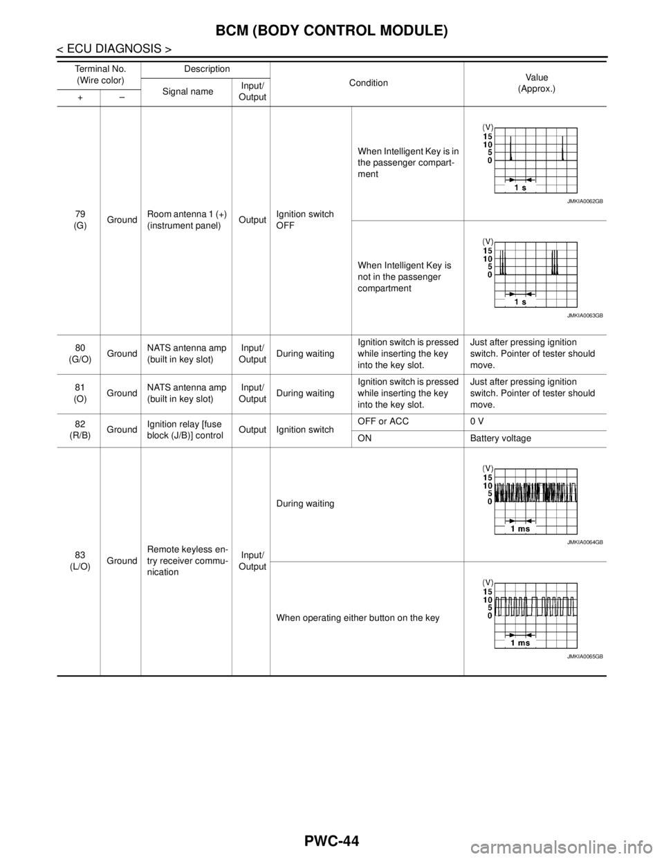
PWC-44
< ECU DIAGNOSIS >
BCM (BODY CONTROL MODULE)
79
(G)GroundRoom antenna 1 (+)
(instrument panel)OutputIgnition switch
OFFWhen Intelligent Key is in
the passenger compart-
ment
When Intelligent Key is
not in the passenger
compartment
80
(G/O)GroundNATS antenna amp
(built in key slot)Input/
OutputDuring waitingIgnition switch is pressed
while inserting the key
into the key slot.Just after pressing ignition
switch. Pointer of tester should
move.
81
(O)GroundNATS antenna amp
(built in key slot)Input/
OutputDuring waitingIgnition switch is pressed
while inserting the key
into the key slot.Just after pressing ignition
switch. Pointer of tester should
move.
82
(R/B)GroundIgnition relay [fuse
block (J/B)] controlOutput Ignition switchOFF or ACC 0 V
ON Battery voltage
83
(L/O)GroundRemote keyless en-
try receiver commu-
nicationInput/
OutputDuring waiting
When operating either button on the key Te r m i n a l N o .
(Wire color)Description
ConditionVa l u e
(Approx.)
Signal nameInput/
Output +–
JMKIA0062GB
JMKIA0063GB
JMKIA0064GB
JMKIA0065GB
Page 3681 of 5121

BCM (BODY CONTROL MODULE)
PWC-51
< ECU DIAGNOSIS >
C
D
E
F
G
H
I
J
L
MA
B
PWC
N
O
P
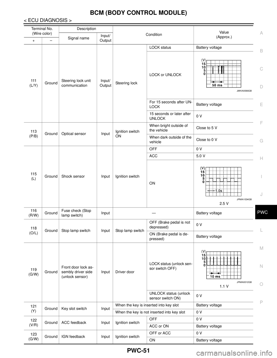
111
(L/Y)GroundSteering lock unit
communicationInput/
OutputSteering lockLOCK status Battery voltage
LOCK or UNLOCK
For 15 seconds after UN-
LOCKBattery voltage
15 seconds or later after
UNLOCK0 V
11 3
(P/B)Ground Optical sensor InputIgnition switch
ONWhen bright outside of
the vehicleClose to 5 V
When dark outside of the
vehicleClose to 0 V
11 5
(L)Ground Shock sensor Input Ignition switchOFF 0 V
ACC 5.0 V
ON
2.5 V
11 6
(R/W)GroundFuse check (Stop
lamp switch)Input — Battery voltage
11 8
(O/L)Ground Stop lamp switch Input Stop lamp switchOFF (Brake pedal is not
depressed)0 V
ON (Brake pedal is de-
pressed)Battery voltage
11 9
(G/W)GroundFront door lock as-
sembly driver side
(unlock sensor)Input Driver doorLOCK status (unlock sen-
sor switch OFF)
1.1 V
UNLOCK status (unlock
sensor switch ON)0 V
121
(Y)Ground Key slot switch InputWhen the key is inserted into key slot Battery voltage
When the key is not inserted into key slot 0 V
122
(V/R)Ground ACC feedback Input Ignition switchOFF 0 V
ACC or ON Battery voltage
123
(G/W)Ground IGN feedback Input Ignition switchOFF or ACC 0 V
ON Battery voltage Te r m i n a l N o .
(Wire color)Description
ConditionVa l u e
(Approx.)
Signal nameInput/
Output +–
JMKIA0066GB
JPMIA1034GB
JPMIA0012GB
Page 3742 of 5121

POWER SUPPLY AND GROUND CIRCUIT
RF-11
< COMPONENT DIAGNOSIS >
C
D
E
F
G
H
I
J
L
MA
B
RF
N
O
P
COMPONENT DIAGNOSIS
POWER SUPPLY AND GROUND CIRCUIT
BCM
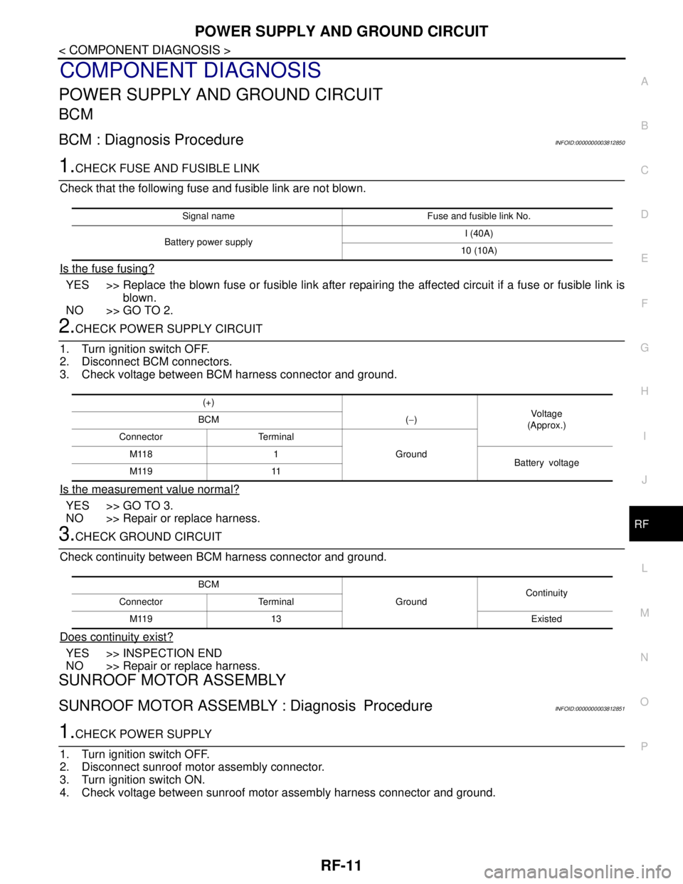
BCM : Diagnosis ProcedureINFOID:0000000003812850
1.CHECK FUSE AND FUSIBLE LINK
Check that the following fuse and fusible link are not blown.
Is the fuse fusing?
YES >> Replace the blown fuse or fusible link after repairing the affected circuit if a fuse or fusible link is
blown.
NO >> GO TO 2.
2.CHECK POWER SUPPLY CIRCUIT
1. Turn ignition switch OFF.
2. Disconnect BCM connectors.
3. Check voltage between BCM harness connector and ground.
Is the measurement value normal?
YES >> GO TO 3.
NO >> Repair or replace harness.
3.CHECK GROUND CIRCUIT
Check continuity between BCM harness connector and ground.
Does continuity exist?
YES >> INSPECTION END
NO >> Repair or replace harness.
SUNROOF MOTOR ASSEMBLY
SUNROOF MOTOR ASSEMBLY : Diagnosis ProcedureINFOID:0000000003812851
1.CHECK POWER SUPPLY
1. Turn ignition switch OFF.
2. Disconnect sunroof motor assembly connector.
3. Turn ignition switch ON.
4. Check voltage between sunroof motor assembly harness connector and ground.
Signal name Fuse and fusible link No.
Battery power supplyI (40A)
10 (10A)
(+)
Vol tag e
(Approx.) BCM (−)
Ground Connector Terminal
M118 1
Battery voltage
M119 11
BCM
GroundContinuity
Connector Terminal
M119 13 Existed