Page 3140 of 5121
![NISSAN TEANA 2008 Service Manual LAN
CAN COMMUNICATION CIRCUIT
LAN-73
< COMPONENT DIAGNOSIS >[CAN SYSTEM (TYPE 4)]
C
D
E
F
G
H
I
J
K
L B A
O
P N
Inspection result
Reproduced>>GO TO 6.
Non-reproduced>>Start the diagnosis again. Follow NISSAN TEANA 2008 Service Manual LAN
CAN COMMUNICATION CIRCUIT
LAN-73
< COMPONENT DIAGNOSIS >[CAN SYSTEM (TYPE 4)]
C
D
E
F
G
H
I
J
K
L B A
O
P N
Inspection result
Reproduced>>GO TO 6.
Non-reproduced>>Start the diagnosis again. Follow](/manual-img/5/57391/w960_57391-3139.png)
LAN
CAN COMMUNICATION CIRCUIT
LAN-73
< COMPONENT DIAGNOSIS >[CAN SYSTEM (TYPE 4)]
C
D
E
F
G
H
I
J
K
L B A
O
P N
Inspection result
Reproduced>>GO TO 6.
Non-reproduced>>Start the diagnosis again. Follow the trouble diagnosis procedure when past error is
detected.
6.CHECK UNIT REPRODUCTION
Perform the reproduction test as per the following procedure for each unit.
1. Turn the ignition switch OFF.
2. Disconnect the battery cable from the negative terminal.
3. Disconnect one of the unit connectors of CAN communication system.
NOTE:
ECM and IPDM E/R have a termination circuit. Check other units first.
4. Connect the battery cable to the negative terminal. Check if the symptoms described in the “Symptom
(Results from interview with customer)” are reproduced.
NOTE:
Although unit-related error symptoms occur, do not confuse them with other symptoms.
Inspection result
Reproduced>>Connect the connector. Check other units as per the above procedure.
Non-reproduced>>Replace the unit whose connector was disconnected.
Page 3156 of 5121
![NISSAN TEANA 2008 Service Manual LAN
CAN COMMUNICATION CIRCUIT
LAN-89
< COMPONENT DIAGNOSIS >[CAN SYSTEM (TYPE 6)]
C
D
E
F
G
H
I
J
K
L B A
O
P N
Inspection result
Reproduced>>GO TO 6.
Non-reproduced>>Start the diagnosis again. Follow NISSAN TEANA 2008 Service Manual LAN
CAN COMMUNICATION CIRCUIT
LAN-89
< COMPONENT DIAGNOSIS >[CAN SYSTEM (TYPE 6)]
C
D
E
F
G
H
I
J
K
L B A
O
P N
Inspection result
Reproduced>>GO TO 6.
Non-reproduced>>Start the diagnosis again. Follow](/manual-img/5/57391/w960_57391-3155.png)
LAN
CAN COMMUNICATION CIRCUIT
LAN-89
< COMPONENT DIAGNOSIS >[CAN SYSTEM (TYPE 6)]
C
D
E
F
G
H
I
J
K
L B A
O
P N
Inspection result
Reproduced>>GO TO 6.
Non-reproduced>>Start the diagnosis again. Follow the trouble diagnosis procedure when past error is
detected.
6.CHECK UNIT REPRODUCTION
Perform the reproduction test as per the following procedure for each unit.
1. Turn the ignition switch OFF.
2. Disconnect the battery cable from the negative terminal.
3. Disconnect one of the unit connectors of CAN communication system.
NOTE:
ECM and IPDM E/R have a termination circuit. Check other units first.
4. Connect the battery cable to the negative terminal. Check if the symptoms described in the “Symptom
(Results from interview with customer)” are reproduced.
NOTE:
Although unit-related error symptoms occur, do not confuse them with other symptoms.
Inspection result
Reproduced>>Connect the connector. Check other units as per the above procedure.
Non-reproduced>>Replace the unit whose connector was disconnected.
Page 3172 of 5121
![NISSAN TEANA 2008 Service Manual LAN
CAN COMMUNICATION CIRCUIT
LAN-105
< COMPONENT DIAGNOSIS >[CAN SYSTEM (TYPE 9)]
C
D
E
F
G
H
I
J
K
L B A
O
P N
Inspection result
Reproduced>>GO TO 6.
Non-reproduced>>Start the diagnosis again. Follo NISSAN TEANA 2008 Service Manual LAN
CAN COMMUNICATION CIRCUIT
LAN-105
< COMPONENT DIAGNOSIS >[CAN SYSTEM (TYPE 9)]
C
D
E
F
G
H
I
J
K
L B A
O
P N
Inspection result
Reproduced>>GO TO 6.
Non-reproduced>>Start the diagnosis again. Follo](/manual-img/5/57391/w960_57391-3171.png)
LAN
CAN COMMUNICATION CIRCUIT
LAN-105
< COMPONENT DIAGNOSIS >[CAN SYSTEM (TYPE 9)]
C
D
E
F
G
H
I
J
K
L B A
O
P N
Inspection result
Reproduced>>GO TO 6.
Non-reproduced>>Start the diagnosis again. Follow the trouble diagnosis procedure when past error is
detected.
6.CHECK UNIT REPRODUCTION
Perform the reproduction test as per the following procedure for each unit.
1. Turn the ignition switch OFF.
2. Disconnect the battery cable from the negative terminal.
3. Disconnect one of the unit connectors of CAN communication system.
NOTE:
ECM and IPDM E/R have a termination circuit. Check other units first.
4. Connect the battery cable to the negative terminal. Check if the symptoms described in the “Symptom
(Results from interview with customer)” are reproduced.
NOTE:
Although unit-related error symptoms occur, do not confuse them with other symptoms.
Inspection result
Reproduced>>Connect the connector. Check other units as per the above procedure.
Non-reproduced>>Replace the unit whose connector was disconnected.
Page 3228 of 5121

MA-40
< ON-VEHICLE MAINTENANCE >
CHASSIS MAINTENANCE
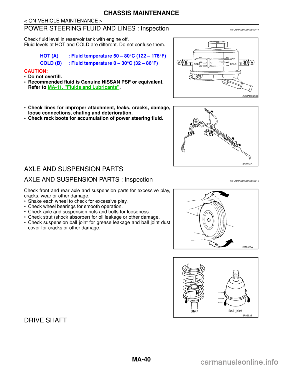
POWER STEERING FLUID AND LINES : Inspection
INFOID:0000000003862441
Check fluid level in reservoir tank with engine off.
Fluid levels at HOT and COLD are different. Do not confuse them.
CAUTION:
Do not overfill.
Recommended fluid is Genuine NISSAN PSF or equivalent.
Refer to MA-11, "
Fluids and Lubricants".
Check lines for improper attachment, leaks, cracks, damage,
loose connections, chafing and deterioration.
Check rack boots for accumulation of power steering fluid.
AXLE AND SUSPENSION PARTS
AXLE AND SUSPENSION PARTS : InspectionINFOID:0000000003858316
Check front and rear axle and suspension parts for excessive play,
cracks, wear or other damage.
Shake each wheel to check for excessive play.
Check wheel bearings for smooth operation.
Check axle and suspension nuts and bolts for looseness.
Check strut (shock absorber) for oil leakage or other damage.
Check suspension ball joint for grease leakage and ball joint dust
cover for cracks or other damage.
DRIVE SHAFT
HOT (A) : Fluid temperature 50 – 80°C (122 – 176°F)
COLD (B) : Fluid temperature 0 – 30°C (32 – 86°F)
ALGIA0002GB
SST851C
SMA525A
SFA392B
Page 3296 of 5121

MWI-42
< COMPONENT DIAGNOSIS >
POWER SUPPLY AND GROUND CIRCUIT
POWER SUPPLY AND GROUND CIRCUIT
COMBINATION METER
COMBINATION METER : Diagnosis ProcedureINFOID:0000000003792567
1.CHECK FUSE
Check for blown fuses.
Is the inspection result normal?
YES >> GO TO 2.
NO >> Be sure to eliminate cause of malfunction before installing new fuse.
2.CHECK POWER SUPPLY CIRCUIT
Check voltage between combination meter harness connector terminals and ground.
Is the inspection result normal?
YES >> GO TO 3.
NO >> Check harness between combination meter and fuse.
3.CHECK GROUND CIRCUIT
1. Turn ignition switch OFF.
2. Disconnect combination meter connector.
3. Check continuity between combination meter harness connector terminals and ground.
Is the inspection result normal?
YES >> INSPECTION END
NO >> Repair harness or connector.
BCM (BODY CONTROL MODULE)
BCM (BODY CONTROL MODULE) : Diagnosis ProcedureINFOID:0000000003900505
1.CHECK FUSE AND FUSIBLE LINK
Check that the following fuse and fusible link are not blown.
Power source Fuse No.
Battery 11
Ignition switch ON or START 4
Te r m i n a l s
Vol tag e
(Approx.) (+) (-)
Combination meter
Ground Connector Terminal
M341
Battery voltage
2
Te r m i n a l s
Continuity (+) (-)
Combination meter
Ground Connector Terminal
M343
Existed
23
Page 3297 of 5121

MWI
POWER SUPPLY AND GROUND CIRCUIT
MWI-43
< COMPONENT DIAGNOSIS >
C
D
E
F
G
H
I
J
K
L
MB A
O
P
Is the fuse fusing?
YES >> Replace the blown fuse or fusible link after repairing the affected circuit if a fuse or fusible link is
blown.
NO >> GO TO 2.
2.CHECK POWER SUPPLY CIRCUIT
1. Turn ignition switch OFF.
2. Disconnect BCM connectors.
3. Check voltage between BCM harness connector and ground.
Is the measurement value normal?
YES >> GO TO 3.
NO >> Repair harness or connector.
3.CHECK GROUND CIRCUIT
Check continuity between BCM harness connector and ground.
Does continuity exist?
YES >> INSPECTION END
NO >> Repair harness or connector.
IPDM E/R (INTELLIGENT POWER DISTRIBUTION MODULE ENGINE ROOM)
IPDM E/R (INTELLIGENT POWER DISTRIBUTION MODULE ENGINE ROOM) : Di-
agnosis Procedure
INFOID:0000000003900506
1.CHECK FUSES AND FUSIBLE LINK
Check that the following IPDM E/R fuses or fusible links are not blown.
Is the fuse fusing?
YES >> Replace the blown fuse or fusible link after repairing the affected circuit if a fuse or fusible link is
blown.
NO >> GO TO 2.
2.CHECK POWER SUPPLY CIRCUIT
1. Turn ignition switch OFF.
Signal name Fuse and fusible link No.
Battery power supplyI
10
Te r m i n a l s
Vo l ta g e
(Approx.) (+) (−)
BCM
Ground Connector Terminal
M118 1
Battery voltage
M119 11
BCM
GroundContinuity
Connector Terminal
M119 13 Existed
Signal name Fuses and fusible link No.
Battery power supplyE
50
51
Page 3334 of 5121

MWI-80
< ECU DIAGNOSIS >
BCM (BODY CONTROL MODULE)
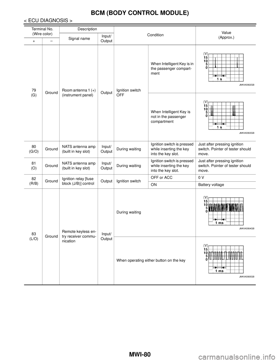
79
(G)GroundRoom antenna 1 (+)
(instrument panel)OutputIgnition switch
OFFWhen Intelligent Key is in
the passenger compart-
ment
When Intelligent Key is
not in the passenger
compartment
80
(G/O)GroundNATS antenna amp
(built in key slot)Input/
OutputDuring waitingIgnition switch is pressed
while inserting the key
into the key slot.Just after pressing ignition
switch. Pointer of tester should
move.
81
(O)GroundNATS antenna amp
(built in key slot)Input/
OutputDuring waitingIgnition switch is pressed
while inserting the key
into the key slot.Just after pressing ignition
switch. Pointer of tester should
move.
82
(R/B)GroundIgnition relay [fuse
block (J/B)] controlOutput Ignition switchOFF or ACC 0 V
ON Battery voltage
83
(L/O)GroundRemote keyless en-
try receiver commu-
nicationInput/
OutputDuring waiting
When operating either button on the key Te r m i n a l N o .
(Wire color)Description
ConditionVa l u e
(Approx.)
Signal nameInput/
Output +–
JMKIA0062GB
JMKIA0063GB
JMKIA0064GB
JMKIA0065GB
Page 3341 of 5121

MWI
BCM (BODY CONTROL MODULE)
MWI-87
< ECU DIAGNOSIS >
C
D
E
F
G
H
I
J
K
L
MB A
O
P
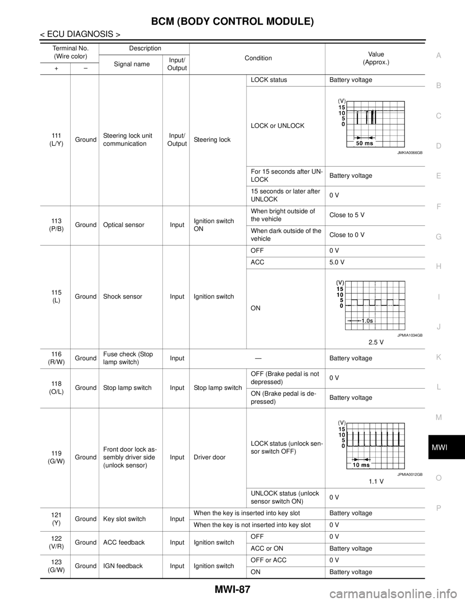
111
(L/Y)GroundSteering lock unit
communicationInput/
OutputSteering lockLOCK status Battery voltage
LOCK or UNLOCK
For 15 seconds after UN-
LOCKBattery voltage
15 seconds or later after
UNLOCK0 V
11 3
(P/B)Ground Optical sensor InputIgnition switch
ONWhen bright outside of
the vehicleClose to 5 V
When dark outside of the
vehicleClose to 0 V
11 5
(L)Ground Shock sensor Input Ignition switchOFF 0 V
ACC 5.0 V
ON
2.5 V
11 6
(R/W)GroundFuse check (Stop
lamp switch)Input — Battery voltage
11 8
(O/L)Ground Stop lamp switch Input Stop lamp switchOFF (Brake pedal is not
depressed)0 V
ON (Brake pedal is de-
pressed)Battery voltage
11 9
(G/W)GroundFront door lock as-
sembly driver side
(unlock sensor)Input Driver doorLOCK status (unlock sen-
sor switch OFF)
1.1 V
UNLOCK status (unlock
sensor switch ON)0 V
121
(Y)Ground Key slot switch InputWhen the key is inserted into key slot Battery voltage
When the key is not inserted into key slot 0 V
122
(V/R)Ground ACC feedback Input Ignition switchOFF 0 V
ACC or ON Battery voltage
123
(G/W)Ground IGN feedback Input Ignition switchOFF or ACC 0 V
ON Battery voltage Te r m i n a l N o .
(Wire color)Description
ConditionVa l u e
(Approx.)
Signal nameInput/
Output +–
JMKIA0066GB
JPMIA1034GB
JPMIA0012GB