Page 2975 of 5121
INL-96
< ON-VEHICLE REPAIR >
PERSONAL LAMP
PERSONAL LAMP
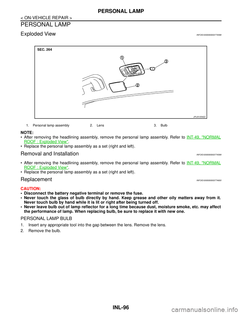
Exploded ViewINFOID:0000000003774598
NOTE:
After removing the headlining assembly, remove the personal lamp assembly. Refer to INT-49, "
NORMAL
ROOF : Exploded View".
Replace the personal lamp assembly as a set (right and left).
Removal and InstallationINFOID:0000000003774599
After removing the headlining assembly, remove the personal lamp assembly. Refer to INT-49, "NORMAL
ROOF : Exploded View".
Replace the personal lamp assembly as a set (right and left).
ReplacementINFOID:0000000003774600
CAUTION:
Disconnect the battery negative terminal or remove the fuse.
Never touch the glass of bulb directly by hand. Keep grease and other oily matters away from it.
Never touch bulb by hand while it is lit or right after being turned off.
Never leave bulb out of lamp reflector for a long time because dust, moisture smoke, etc. may affect
the performance of lamp. When replacing bulb, be sure to replace it with new one.
PERSONAL LAMP BULB
1. Insert any appropriate tool into the gap between the lens. Remove the lens.
2. Remove the bulb.
1. Personal lamp assembly 2. Lens 3. Bulb
JPLIA1254ZZ
Page 2976 of 5121
TRUNK ROOM LAMP
INL-97
< ON-VEHICLE REPAIR >
C
D
E
F
G
H
I
J
K
MA
B
INL
N
O
P
TRUNK ROOM LAMP
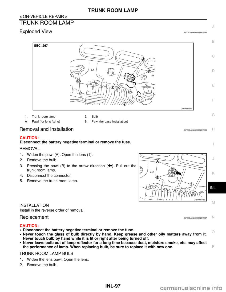
Exploded ViewINFOID:0000000003812235
Removal and InstallationINFOID:0000000003812236
CAUTION:
Disconnect the battery negative terminal or remove the fuse.
REMOVAL
1. Widen the pawl (A). Open the lens (1).
2. Remove the bulb.
3. Pressing the pawl (B) to the arrow direction ( ). Pull out the
trunk room lamp.
4. Disconnect the connector.
5. Remove the trunk room lamp.
INSTALLATION
Install in the reverse order of removal.
ReplacementINFOID:0000000003812237
CAUTION:
Disconnect the battery negative terminal or remove the fuse.
Never touch the glass of bulb directly by hand. Keep grease and other oily matters away from it.
Never touch bulb by hand while it is lit or right after being turned off.
Never leave bulb out of lamp reflector for a long time because dust, moisture smoke, etc. may affect
the performance of lamp. When replacing bulb, be sure to replace it with new one.
TRUNK ROOM LAMP BULB
1. Widen the lens pawl. Open the lens.
2. Remove the bulb.
1. Trunk room lamp 2. Bulb
A Pawl (for lens fixing) B. Pawl (for case installation)
J P L I A 111 6 Z Z
J P L I A 111 7 Z Z
Page 3052 of 5121
IP-12
< ON-VEHICLE REPAIR >
INSTRUMENT PANEL ASSEMBLY
Removal and Installation
INFOID:0000000003816778
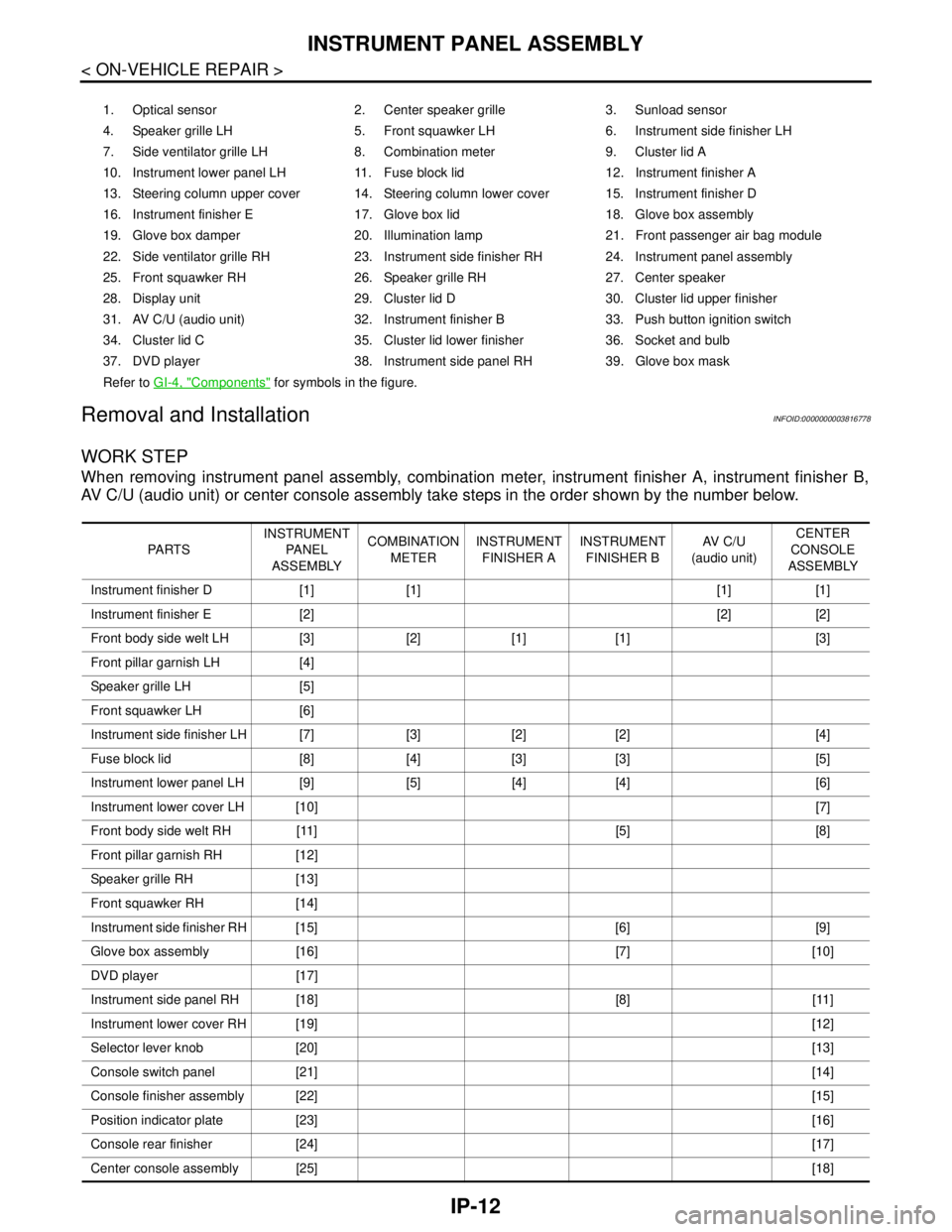
WORK STEP
When removing instrument panel assembly, combination meter, instrument finisher A, instrument finisher B,
AV C/U (audio unit) or center console assembly take steps in the order shown by the number below.
1. Optical sensor 2. Center speaker grille 3. Sunload sensor
4. Speaker grille LH 5. Front squawker LH 6. Instrument side finisher LH
7. Side ventilator grille LH 8. Combination meter 9. Cluster lid A
10. Instrument lower panel LH 11. Fuse block lid 12. Instrument finisher A
13. Steering column upper cover 14. Steering column lower cover 15. Instrument finisher D
16. Instrument finisher E 17. Glove box lid 18. Glove box assembly
19. Glove box damper 20. Illumination lamp 21. Front passenger air bag module
22. Side ventilator grille RH 23. Instrument side finisher RH 24. Instrument panel assembly
25. Front squawker RH 26. Speaker grille RH 27. Center speaker
28. Display unit 29. Cluster lid D 30. Cluster lid upper finisher
31. AV C/U (audio unit) 32. Instrument finisher B 33. Push button ignition switch
34. Cluster lid C 35. Cluster lid lower finisher 36. Socket and bulb
37. DVD player 38. Instrument side panel RH 39. Glove box mask
Refer to GI-4, "
Components" for symbols in the figure.
PA R T SINSTRUMENT
PA N E L
ASSEMBLYCOMBINATION
METERINSTRUMENT
FINISHER AINSTRUMENT
FINISHER BAV C / U
(audio unit)CENTER
CONSOLE
ASSEMBLY
Instrument finisher D [1] [1] [1] [1]
Instrument finisher E [2] [2] [2]
Front body side welt LH [3] [2] [1] [1] [3]
Front pillar garnish LH [4]
Speaker grille LH [5]
Front squawker LH [6]
Instrument side finisher LH [7] [3] [2] [2] [4]
Fuse block lid [8] [4] [3] [3] [5]
Instrument lower panel LH [9] [5] [4] [4] [6]
Instrument lower cover LH [10][7]
Front body side welt RH [11] [5] [8]
Front pillar garnish RH [12]
Speaker grille RH [13]
Front squawker RH [14]
Instrument side finisher RH [15] [6] [9]
Glove box assembly [16] [7] [10]
DVD player [17]
Instrument side panel RH [18] [8] [11]
Instrument lower cover RH [19][12]
Selector lever knob [20][13]
Console switch panel [21][14]
Console finisher assembly [22][15]
Position indicator plate [23][16]
Console rear finisher [24][17]
Center console assembly [25][18]
Page 3054 of 5121
IP-14
< ON-VEHICLE REPAIR >
INSTRUMENT PANEL ASSEMBLY
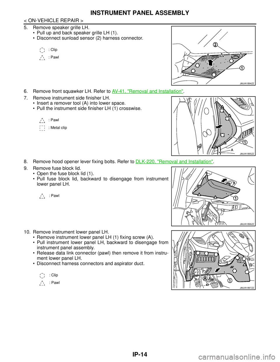
5. Remove speaker grille LH.
Pull up and back speaker grille LH (1).
Disconnect sunload sensor (2) harness connector.
6. Remove front squawker LH. Refer to AV-41, "
Removal and Installation".
7. Remove instrument side finisher LH.
Insert a remover tool (A) into lower space.
Pull the instrument side finisher LH (1) crosswise.
8. Remove hood opener lever fixing bolts. Refer to DLK-220, "
Removal and Installation".
9. Remove fuse block lid.
Open the fuse block lid (1).
Pull fuse block lid, backward to disengage from instrument
lower panel LH.
10. Remove instrument lower panel LH.
Remove instrument lower panel LH (1) fixing screw (A).
Pull instrument lower panel LH, backward to disengage from
instrument panel assembly.
Release data link connector (pawl) then remove it from instru-
ment lower panel LH.
Disconnect harness connectors and aspirator duct.
: Clip
: Pawl
JMJIA1894ZZ
: Pawl
: Metal clip
JMJIA1895ZZ
: Pawl
JMJIA1896ZZ
: Clip
: Pawl
JMJIA1897ZZ
Page 3063 of 5121
CENTER CONSOLE ASSEMBLY
IP-23
< ON-VEHICLE REPAIR >
C
D
E
F
G
H
I
K
L
MA
B
IP
N
O
P
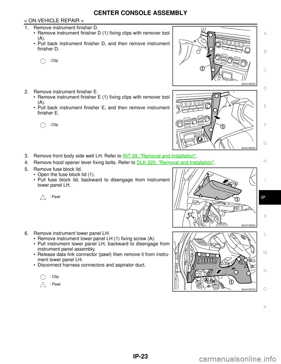
1. Remove instrument finisher D.
Remove instrument finisher D (1) fixing clips with remover tool
(A).
Pull back instrument finisher D, and then remove instrument
finisher D.
2. Remove instrument finisher E.
Remove instrument finisher E (1) fixing clips with remover tool
(A).
Pull back instrument finisher E, and then remove instrument
finisher E.
3. Remove front body side welt LH. Refer to INT-39, "
Removal and Installation".
4. Remove hood opener lever fixing bolts. Refer to DLK-220, "
Removal and Installation".
5. Remove fuse block lid.
Open the fuse block lid (1).
Pull fuse block lid, backward to disengage from instrument
lower panel LH.
6. Remove instrument lower panel LH.
Remove instrument lower panel LH (1) fixing screw (A).
Pull instrument lower panel LH, backward to disengage from
instrument panel assembly.
Release data link connector (pawl) then remove it from instru-
ment lower panel LH.
Disconnect harness connectors and aspirator duct.
: Clip
JMJIA1892ZZ
: Clip
JMJIA1893ZZ
: Pawl
JMJIA1896ZZ
: Clip
: Pawl
JMJIA1897ZZ
Page 3075 of 5121
![NISSAN TEANA 2008 Service Manual LAN-8
< FUNCTION DIAGNOSIS >[CAN FUNDAMENTAL]
TROUBLE DIAGNOSIS
TROUBLE DIAGNOSIS
Condition of Error DetectionINFOID:0000000003767670
“U1000” or “U1001” is indicated on SELF-DIAG RESULTS on CO NISSAN TEANA 2008 Service Manual LAN-8
< FUNCTION DIAGNOSIS >[CAN FUNDAMENTAL]
TROUBLE DIAGNOSIS
TROUBLE DIAGNOSIS
Condition of Error DetectionINFOID:0000000003767670
“U1000” or “U1001” is indicated on SELF-DIAG RESULTS on CO](/manual-img/5/57391/w960_57391-3074.png)
LAN-8
< FUNCTION DIAGNOSIS >[CAN FUNDAMENTAL]
TROUBLE DIAGNOSIS
TROUBLE DIAGNOSIS
Condition of Error DetectionINFOID:0000000003767670
“U1000” or “U1001” is indicated on SELF-DIAG RESULTS on CONSULT-III if CAN communication signal is
not transmitted or received between units for 2 seconds or more.
CAN COMMUNICATION SYSTEM ERROR
CAN communication line open (CAN-H, CAN-L, or both)
CAN communication line short (ground, between CAN communication lines, other harnesses)
Error of CAN communication control circuit of the unit connected to CAN communication line
WHEN “U1000” OR “U1001” IS INDICATED EVEN THOUGH CAN COMMUNICATION SYSTEM IS
NORMAL
Removal/installation of parts: Error may be detected when removing and installing CAN communication unit
and related parts while turning the ignition switch ON. (A DTC except for CAN communication may be
detected.)
Fuse blown out (removed): CAN communication of the unit may cease.
Voltage drop: Error may be detected if voltage drops due to discharged battery when turning the ignition
switch ON (Depending on the control unit which carries out CAN communication).
Error may be detected if the power supply circuit of the control unit, which carries out CAN communication,
malfunctions (Depending on the control unit which carries out CAN communication).
Error may be detected if reprogramming is not completed normally.
NOTE:
CAN communication system is normal if “U1000” or “U1001” is indicated on SELF-DIAG RESULTS of CON-
SULT-III under the above conditions. Erase the memory of the self-diagnosis of each unit.
Symptom When Error Occurs in CAN Communication SystemINFOID:0000000003767671
In CAN communication system, multiple units mutually transmit and receive signals. Each unit cannot transmit
and receive signals if any error occurs on CAN communication line. Under this condition, multiple control units
related to the root cause malfunction or go into fail-safe mode.
ERROR EXAMPLE
NOTE:
Each vehicle differs in symptom of each unit under fail-safe mode and CAN communication line wiring.
Refer to LAN-19, "
Abbreviation List" for the unit abbreviation.
Example: TCM branch line open circuit
SKIB8738E
Unit name Symptom
ECM Engine torque limiting is affected, and shift harshness increases.
BCM Reverse warning chime does not sound.
Page 3114 of 5121
![NISSAN TEANA 2008 Service Manual LAN
CAN COMMUNICATION CIRCUIT
LAN-47
< COMPONENT DIAGNOSIS >[CAN]
C
D
E
F
G
H
I
J
K
L B A
O
P N
Inspection result
Reproduced>>GO TO 6.
Non-reproduced>>Start the diagnosis again. Follow the trouble dia NISSAN TEANA 2008 Service Manual LAN
CAN COMMUNICATION CIRCUIT
LAN-47
< COMPONENT DIAGNOSIS >[CAN]
C
D
E
F
G
H
I
J
K
L B A
O
P N
Inspection result
Reproduced>>GO TO 6.
Non-reproduced>>Start the diagnosis again. Follow the trouble dia](/manual-img/5/57391/w960_57391-3113.png)
LAN
CAN COMMUNICATION CIRCUIT
LAN-47
< COMPONENT DIAGNOSIS >[CAN]
C
D
E
F
G
H
I
J
K
L B A
O
P N
Inspection result
Reproduced>>GO TO 6.
Non-reproduced>>Start the diagnosis again. Follow the trouble diagnosis procedure when past error is
detected.
6.CHECK UNIT REPRODUCTION
Perform the reproduction test as per the following procedure for each unit.
1. Turn the ignition switch OFF.
2. Disconnect the battery cable from the negative terminal.
3. Disconnect one of the unit connectors of CAN communication system.
NOTE:
ECM and IPDM E/R have a termination circuit. Check other units first.
4. Connect the battery cable to the negative terminal. Check if the symptoms described in the “Symptom
(Results from interview with customer)” are reproduced.
NOTE:
Although unit-related error symptoms occur, do not confuse them with other symptoms.
Inspection result
Reproduced>>Connect the connector. Check other units as per the above procedure.
Non-reproduced>>Replace the unit whose connector was disconnected.
Page 3126 of 5121
![NISSAN TEANA 2008 Service Manual LAN
CAN COMMUNICATION CIRCUIT
LAN-59
< COMPONENT DIAGNOSIS >[CAN SYSTEM (TYPE 2)]
C
D
E
F
G
H
I
J
K
L B A
O
P N
Inspection result
Reproduced>>GO TO 6.
Non-reproduced>>Start the diagnosis again. Follow NISSAN TEANA 2008 Service Manual LAN
CAN COMMUNICATION CIRCUIT
LAN-59
< COMPONENT DIAGNOSIS >[CAN SYSTEM (TYPE 2)]
C
D
E
F
G
H
I
J
K
L B A
O
P N
Inspection result
Reproduced>>GO TO 6.
Non-reproduced>>Start the diagnosis again. Follow](/manual-img/5/57391/w960_57391-3125.png)
LAN
CAN COMMUNICATION CIRCUIT
LAN-59
< COMPONENT DIAGNOSIS >[CAN SYSTEM (TYPE 2)]
C
D
E
F
G
H
I
J
K
L B A
O
P N
Inspection result
Reproduced>>GO TO 6.
Non-reproduced>>Start the diagnosis again. Follow the trouble diagnosis procedure when past error is
detected.
6.CHECK UNIT REPRODUCTION
Perform the reproduction test as per the following procedure for each unit.
1. Turn the ignition switch OFF.
2. Disconnect the battery cable from the negative terminal.
3. Disconnect one of the unit connectors of CAN communication system.
NOTE:
ECM and IPDM E/R have a termination circuit. Check other units first.
4. Connect the battery cable to the negative terminal. Check if the symptoms described in the “Symptom
(Results from interview with customer)” are reproduced.
NOTE:
Although unit-related error symptoms occur, do not confuse them with other symptoms.
Inspection result
Reproduced>>Connect the connector. Check other units as per the above procedure.
Non-reproduced>>Replace the unit whose connector was disconnected.