2008 NISSAN TEANA fuse
[x] Cancel search: fusePage 2517 of 5121
GI-24
< PRECAUTION >
PRECAUTIONS
PRECAUTION
PRECAUTIONS
DescriptionINFOID:0000000003852776
Observe the following precautions to ensure safe and proper servicing. These precautions are not
described in each individual section.
Precaution for Supplemental Restraint System (SRS) "AIR BAG" and "SEAT BELT
PRE-TENSIONER"
INFOID:0000000003852830
The Supplemental Restraint System such as “AIR BAG” and “SEAT BELT PRE-TENSIONER”, used along
with a front seat belt, helps to reduce the risk or severity of injury to the driver and front passenger for certain
types of collision. Information necessary to service the system safely is included in the “SRS AIRBAG” and
“SEAT BELT” of this Service Manual.
WARNING:
To avoid rendering the SRS inoperative, which could increase the risk of personal injury or death in
the event of a collision which would result in air bag inflation, all maintenance must be performed by
an authorized NISSAN/INFINITI dealer.
Improper maintenance, including incorrect removal and installation of the SRS, can lead to personal
injury caused by unintentional activation of the system. For removal of Spiral Cable and Air Bag
Module, see the “SRS AIRBAG”.
Never use electrical test equipment on any circuit related to the SRS unless instructed to in this Ser-
vice Manual. SRS wiring harnesses can be identified by yellow and/or orange harnesses or harness
connectors.
Precautions For Xenon Headlamp ServiceINFOID:0000000003852778
WARNING:
Comply with the following warnings to prevent any serious accident.
Disconnect the battery cable (negative terminal) or the power supply fuse before installing, remov-
ing, or touching the xenon headlamp (bulb included). The xenon headlamp contains high-voltage
generated parts.
Never work with wet hands.
Check the xenon headlamp ON-OFF status after assembling it to the vehicle. Never turn the xenon
headlamp ON in other conditions. Connect the power supply to the vehicle-side connector.
(Turning it ON outside the lamp case may cause fire or visual impairments.)
Never touch the bulb glass immediately after turning it OFF. It is extremely hot.
CAUTION:
Comply with the following cautions to prevent any error and malfunction.
Install the xenon bulb securely. (Insufficient bulb socket installation may melt the bulb, the connec-
tor, the housing, etc. by high-voltage leakage or corona discharge.)
Never perform HID circuit inspection with a tester.
Never touch the xenon bulb glass with hands. Never put oil and grease on it.
Dispose of the used xenon bulb after packing it in thick vinyl without breaking it.
Never wipe out dirt and contamination with organic solvent (thinner, gasoline, etc.).
Precaution Necessary for Steering Wheel Rotation after Battery Disconnect
INFOID:0000000003852856
NOTE:
Before removing and installing any control units, first turn the push-button ignition switch to the LOCK posi-
tion, then disconnect both battery cables.
After finishing work, confirm that all control unit connectors are connected properly, then re-connect both
battery cables.
Always use CONSULT-III to perform self-diagnosis as a part of each function inspection after finishing work.
If a DTC is detected, perform trouble diagnosis according to self-diagnosis results.
This vehicle is equipped with a push-button ignition switch and a steering lock unit.
If the battery is disconnected or discharged, the steering wheel will lock and cannot be turned.
Page 2531 of 5121
GI-38
< BASIC INSPECTION >
SERVICE INFORMATION FOR ELECTRICAL INCIDENT
TESTING FOR “OPENS” IN THE CIRCUIT
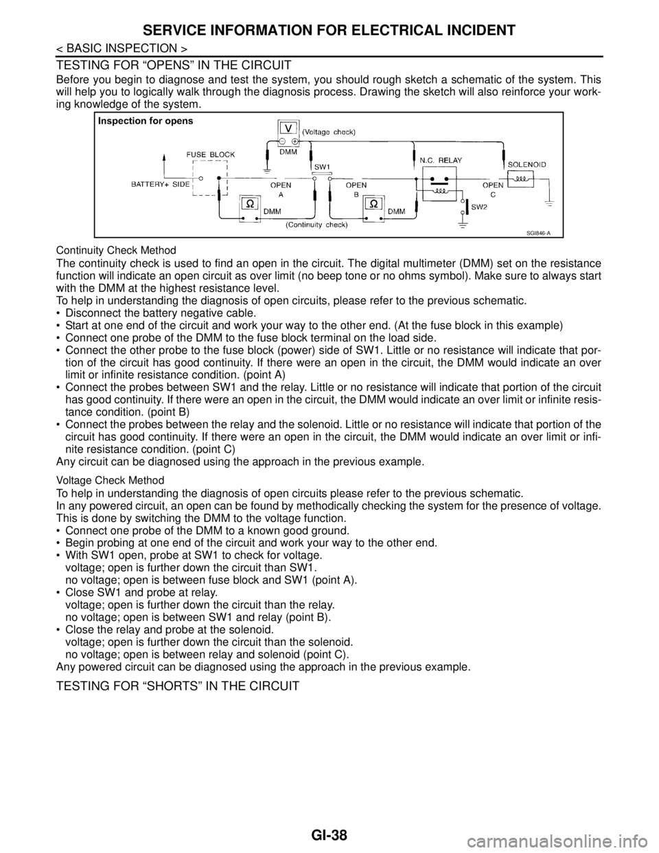
Before you begin to diagnose and test the system, you should rough sketch a schematic of the system. This
will help you to logically walk through the diagnosis process. Drawing the sketch will also reinforce your work-
ing knowledge of the system.
Continuity Check Method
The continuity check is used to find an open in the circuit. The digital multimeter (DMM) set on the resistance
function will indicate an open circuit as over limit (no beep tone or no ohms symbol). Make sure to always start
with the DMM at the highest resistance level.
To help in understanding the diagnosis of open circuits, please refer to the previous schematic.
Disconnect the battery negative cable.
Start at one end of the circuit and work your way to the other end. (At the fuse block in this example)
Connect one probe of the DMM to the fuse block terminal on the load side.
Connect the other probe to the fuse block (power) side of SW1. Little or no resistance will indicate that por-
tion of the circuit has good continuity. If there were an open in the circuit, the DMM would indicate an over
limit or infinite resistance condition. (point A)
Connect the probes between SW1 and the relay. Little or no resistance will indicate that portion of the circuit
has good continuity. If there were an open in the circuit, the DMM would indicate an over limit or infinite resis-
tance condition. (point B)
Connect the probes between the relay and the solenoid. Little or no resistance will indicate that portion of the
circuit has good continuity. If there were an open in the circuit, the DMM would indicate an over limit or infi-
nite resistance condition. (point C)
Any circuit can be diagnosed using the approach in the previous example.
Voltage Check Method
To help in understanding the diagnosis of open circuits please refer to the previous schematic.
In any powered circuit, an open can be found by methodically checking the system for the presence of voltage.
This is done by switching the DMM to the voltage function.
Connect one probe of the DMM to a known good ground.
Begin probing at one end of the circuit and work your way to the other end.
With SW1 open, probe at SW1 to check for voltage.
voltage; open is further down the circuit than SW1.
no voltage; open is between fuse block and SW1 (point A).
Close SW1 and probe at relay.
voltage; open is further down the circuit than the relay.
no voltage; open is between SW1 and relay (point B).
Close the relay and probe at the solenoid.
voltage; open is further down the circuit than the solenoid.
no voltage; open is between relay and solenoid (point C).
Any powered circuit can be diagnosed using the approach in the previous example.
TESTING FOR “SHORTS” IN THE CIRCUIT
SGI846-A
Page 2532 of 5121
SERVICE INFORMATION FOR ELECTRICAL INCIDENT
GI-39
< BASIC INSPECTION >
C
D
E
F
G
H
I
J
K
L
MB
GI
N
O
P
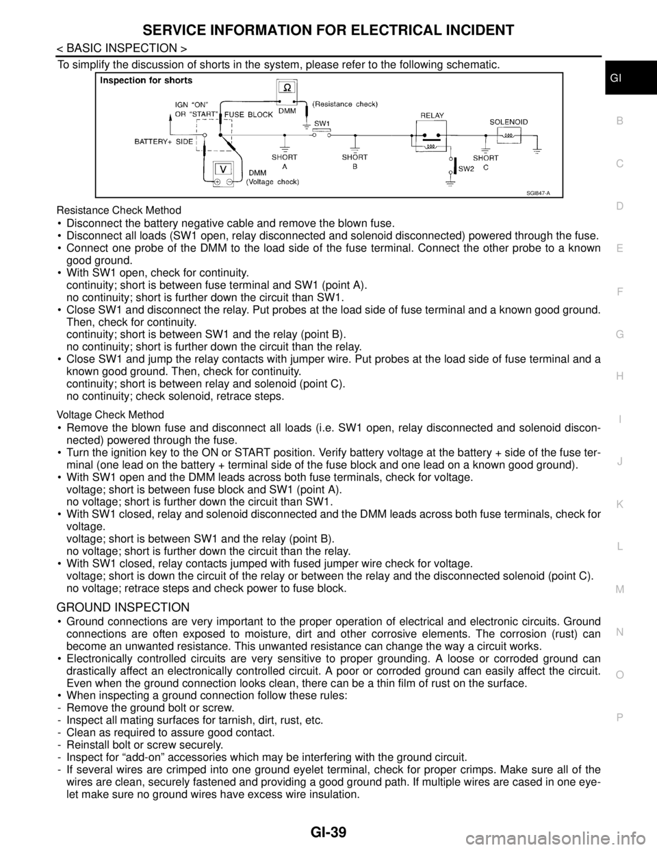
To simplify the discussion of shorts in the system, please refer to the following schematic.
Resistance Check Method
Disconnect the battery negative cable and remove the blown fuse.
Disconnect all loads (SW1 open, relay disconnected and solenoid disconnected) powered through the fuse.
Connect one probe of the DMM to the load side of the fuse terminal. Connect the other probe to a known
good ground.
With SW1 open, check for continuity.
continuity; short is between fuse terminal and SW1 (point A).
no continuity; short is further down the circuit than SW1.
Close SW1 and disconnect the relay. Put probes at the load side of fuse terminal and a known good ground.
Then, check for continuity.
continuity; short is between SW1 and the relay (point B).
no continuity; short is further down the circuit than the relay.
Close SW1 and jump the relay contacts with jumper wire. Put probes at the load side of fuse terminal and a
known good ground. Then, check for continuity.
continuity; short is between relay and solenoid (point C).
no continuity; check solenoid, retrace steps.
Voltage Check Method
Remove the blown fuse and disconnect all loads (i.e. SW1 open, relay disconnected and solenoid discon-
nected) powered through the fuse.
Turn the ignition key to the ON or START position. Verify battery voltage at the battery + side of the fuse ter-
minal (one lead on the battery + terminal side of the fuse block and one lead on a known good ground).
With SW1 open and the DMM leads across both fuse terminals, check for voltage.
voltage; short is between fuse block and SW1 (point A).
no voltage; short is further down the circuit than SW1.
With SW1 closed, relay and solenoid disconnected and the DMM leads across both fuse terminals, check for
voltage.
voltage; short is between SW1 and the relay (point B).
no voltage; short is further down the circuit than the relay.
With SW1 closed, relay contacts jumped with fused jumper wire check for voltage.
voltage; short is down the circuit of the relay or between the relay and the disconnected solenoid (point C).
no voltage; retrace steps and check power to fuse block.
GROUND INSPECTION
Ground connections are very important to the proper operation of electrical and electronic circuits. Ground
connections are often exposed to moisture, dirt and other corrosive elements. The corrosion (rust) can
become an unwanted resistance. This unwanted resistance can change the way a circuit works.
Electronically controlled circuits are very sensitive to proper grounding. A loose or corroded ground can
drastically affect an electronically controlled circuit. A poor or corroded ground can easily affect the circuit.
Even when the ground connection looks clean, there can be a thin film of rust on the surface.
When inspecting a ground connection follow these rules:
- Remove the ground bolt or screw.
- Inspect all mating surfaces for tarnish, dirt, rust, etc.
- Clean as required to assure good contact.
- Reinstall bolt or screw securely.
- Inspect for “add-on” accessories which may be interfering with the ground circuit.
- If several wires are crimped into one ground eyelet terminal, check for proper crimps. Make sure all of the
wires are clean, securely fastened and providing a good ground path. If multiple wires are cased in one eye-
let make sure no ground wires have excess wire insulation.
SGI847-A
Page 2561 of 5121
GW-18
< ON-VEHICLE REPAIR >
FRONT DOOR GLASS
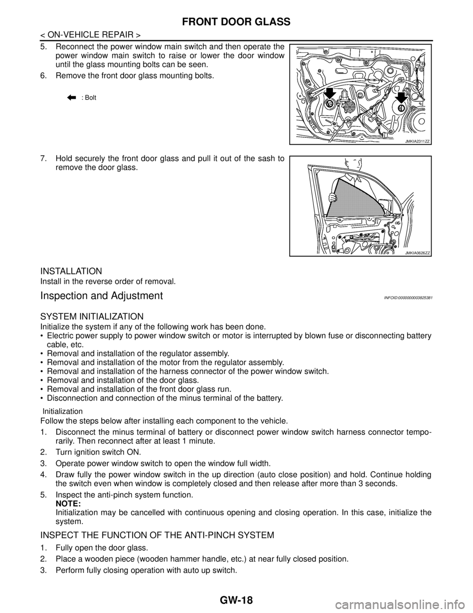
5. Reconnect the power window main switch and then operate the
power window main switch to raise or lower the door window
until the glass mounting bolts can be seen.
6. Remove the front door glass mounting bolts.
7. Hold securely the front door glass and pull it out of the sash to
remove the door glass.
INSTALLATION
Install in the reverse order of removal.
Inspection and AdjustmentINFOID:0000000003825381
SYSTEM INITIALIZATION
Initialize the system if any of the following work has been done.
Electric power supply to power window switch or motor is interrupted by blown fuse or disconnecting battery
cable, etc.
Removal and installation of the regulator assembly.
Removal and installation of the motor from the regulator assembly.
Removal and installation of the harness connector of the power window switch.
Removal and installation of the door glass.
Removal and installation of the front door glass run.
Disconnection and connection of the minus terminal of the battery.
Initialization
Follow the steps below after installing each component to the vehicle.
1. Disconnect the minus terminal of battery or disconnect power window switch harness connector tempo-
rarily. Then reconnect after at least 1 minute.
2. Turn ignition switch ON.
3. Operate power window switch to open the window full width.
4. Draw fully the power window switch in the up direction (auto close position) and hold. Continue holding
the switch even when window is completely closed and then release after more than 3 seconds.
5. Inspect the anti-pinch system function.
NOTE:
Initialization may be cancelled with continuous opening and closing operation. In this case, initialize the
system.
INSPECT THE FUNCTION OF THE ANTI-PINCH SYSTEM
1. Fully open the door glass.
2. Place a wooden piece (wooden hammer handle, etc.) at near fully closed position.
3. Perform fully closing operation with auto up switch.
: Bolt
JMKIA2311ZZ
JMKIA0626ZZ
Page 2564 of 5121
FRONT REGULATOR
GW-21
< ON-VEHICLE REPAIR >
C
D
E
F
G
H
I
J
L
MA
B
GW
N
O
P
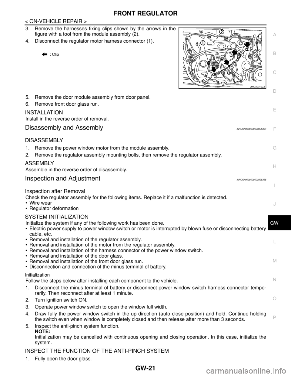
3. Remove the harnesses fixing clips shown by the arrows in the
figure with a tool from the module assembly (2).
4. Disconnect the regulator motor harness connector (1).
5. Remove the door module assembly from door panel.
6. Remove front door glass run.
INSTALLATION
Install in the reverse order of removal.
Disassembly and AssemblyINFOID:0000000003825384
DISASSEMBLY
1. Remove the power window motor from the module assembly.
2. Remove the regulator assembly mounting bolts, then remove the regulator assembly.
ASSEMBLY
Assemble in the reverse order of disassembly.
Inspection and AdjustmentINFOID:0000000003825385
Inspection after Removal
Check the regulator assembly for the following items. Replace it if a malfunction is detected.
Wire wear
Regulator deformation
SYSTEM INITIALIZATION
Initialize the system if any of the following work has been done.
Electric power supply to power window switch or motor is interrupted by blown fuse or disconnecting battery
cable, etc.
Removal and installation of the regulator assembly.
Removal and installation of the motor from the regulator assembly.
Removal and installation of the harness connector of the power window switch.
Removal and installation of the door glass.
Removal and installation of the front door glass run.
Disconnection and connection of the minus terminal of battery.
Initialization
Follow the steps below after installing each component to the vehicle.
1. Disconnect the minus terminal of battery or disconnect power window switch harness connector tempo-
rarily. Then reconnect after at least 1 minute.
2. Turn ignition switch ON.
3. Operate power window switch to open the window full width.
4. Draw fully the power window switch in the up direction (auto close position) and hold. Continue holding
the switch even when window is completely closed and then release after more than 3 seconds.
5. Inspect the anti-pinch system function.
NOTE:
Initialization may be cancelled with continuous opening and closing operation. In this case, initialize the
system.
INSPECT THE FUNCTION OF THE ANTI-PINCH SYSTEM
1. Fully open the door glass.
: Clip
JMKIA2313ZZ
Page 2582 of 5121
PRECAUTIONS
HA-13
< PRECAUTION >
C
D
E
F
G
H
J
K
L
MA
B
HA
N
O
P
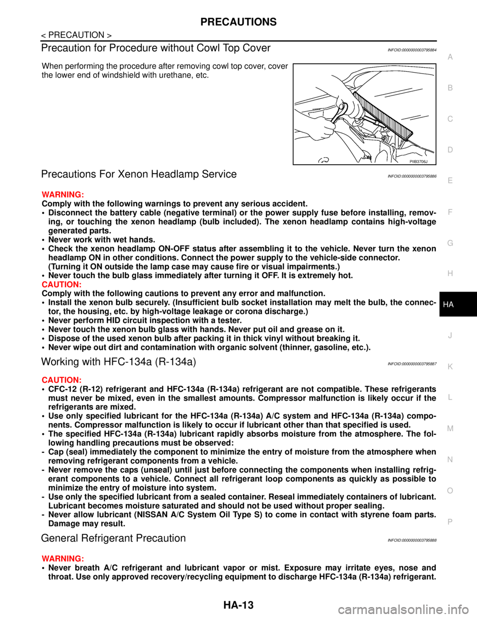
Precaution for Procedure without Cowl Top CoverINFOID:0000000003795884
When performing the procedure after removing cowl top cover, cover
the lower end of windshield with urethane, etc.
Precautions For Xenon Headlamp ServiceINFOID:0000000003795886
WARNING:
Comply with the following warnings to prevent any serious accident.
Disconnect the battery cable (negative terminal) or the power supply fuse before installing, remov-
ing, or touching the xenon headlamp (bulb included). The xenon headlamp contains high-voltage
generated parts.
Never work with wet hands.
Check the xenon headlamp ON-OFF status after assembling it to the vehicle. Never turn the xenon
headlamp ON in other conditions. Connect the power supply to the vehicle-side connector.
(Turning it ON outside the lamp case may cause fire or visual impairments.)
Never touch the bulb glass immediately after turning it OFF. It is extremely hot.
CAUTION:
Comply with the following cautions to prevent any error and malfunction.
Install the xenon bulb securely. (Insufficient bulb socket installation may melt the bulb, the connec-
tor, the housing, etc. by high-voltage leakage or corona discharge.)
Never perform HID circuit inspection with a tester.
Never touch the xenon bulb glass with hands. Never put oil and grease on it.
Dispose of the used xenon bulb after packing it in thick vinyl without breaking it.
Never wipe out dirt and contamination with organic solvent (thinner, gasoline, etc.).
Working with HFC-134a (R-134a)INFOID:0000000003795887
CAUTION:
CFC-12 (R-12) refrigerant and HFC-134a (R-134a) refrigerant are not compatible. These refrigerants
must never be mixed, even in the smallest amounts. Compressor malfunction is likely occur if the
refrigerants are mixed.
Use only specified lubricant for the HFC-134a (R-134a) A/C system and HFC-134a (R-134a) compo-
nents. Compressor malfunction is likely to occur if lubricant other than that specified is used.
The specified HFC-134a (R-134a) lubricant rapidly absorbs moisture from the atmosphere. The fol-
lowing handling precautions must be observed:
- Cap (seal) immediately the component to minimize the entry of moisture from the atmosphere when
removing refrigerant components from a vehicle.
- Never remove the caps (unseal) until just before connecting the components when installing refrig-
erant components to a vehicle. Connect all refrigerant loop components as quickly as possible to
minimize the entry of moisture into system.
- Use only the specified lubricant from a sealed container. Reseal immediately containers of lubricant.
Lubricant becomes moisture saturated and should not be used without proper sealing.
- Never allow lubricant (NISSAN A/C System Oil Type S) to come in contact with styrene foam parts.
Damage may result.
General Refrigerant PrecautionINFOID:0000000003795888
WARNING:
Never breath A/C refrigerant and lubricant vapor or mist. Exposure may irritate eyes, nose and
throat. Use only approved recovery/recycling equipment to discharge HFC-134a (R-134a) refrigerant.
PIIB3706J
Page 2583 of 5121

HA-14
< PRECAUTION >
PRECAUTIONS
Ventilate work area before resuming service if accidental system discharge occurs. Additional health
and safety information may be obtained from refrigerant and lubricant manufacturers.
Never release refrigerant into the air. Use approved recovery/recycling equipment to capture the
refrigerant each time an air conditioning system is discharged.
Wear always eye and hand protection (goggles and gloves) when working with any refrigerant or air
conditioning system.
Never store or heat refrigerant containers above 52°C (126°F).
Never heat a refrigerant container with an open flame; Place the bottom of the container in a warm
pail of water if container warming is required.
Never intentionally drop, puncture, or incinerate refrigerant containers.
Keep refrigerant away from open flames: poisonous gas is produced if refrigerant burns.
Refrigerant displaces oxygen, therefore be certain to work in well ventilated areas to prevent suffo-
cation.
Never pressure test or leakage test HFC-134a (R-134a) service equipment and/or vehicle air condi-
tioning systems with compressed air during repair. Some mixtures of air and HFC-134a (R-134a)
have been shown to be combustible at elevated pressures. These mixtures, if ignited, may cause
injury or property damage. Additional health and safety information may be obtained from refriger-
ant manufacturers.
Refrigerant ConnectionINFOID:0000000003799207
A new type refrigerant connection has been introduced to all refrigerant lines except the following locations.
Expansion valve to evaporator
Refrigerant pressure sensor to liquid tank
O-RING AND REFRIGERANT CONNECTION
CAUTION:
The new and former refrigerant connections use different O-ring configurations. Never confuse O-
rings since they are not interchangeable. Refrigerant may leak at the connection if a wrong O-ring is
installed.
F. Former type refrigerant connection N. New type refrigerant connection
:O-ring size
JPIIA0986ZZ
Page 2693 of 5121
![NISSAN TEANA 2008 Service Manual POWER SUPPLY AND GROUND CIRCUIT
HAC-65
< COMPONENT DIAGNOSIS >[WITHOUT 7 INCH DISPLAY]
C
D
E
F
G
H
J
K
L
MA
B
HAC
N
O
P
POWER SUPPLY AND GROUND CIRCUIT
A/C AUTO AMP.
A/C AUTO AMP. : Diagnosis Procedur NISSAN TEANA 2008 Service Manual POWER SUPPLY AND GROUND CIRCUIT
HAC-65
< COMPONENT DIAGNOSIS >[WITHOUT 7 INCH DISPLAY]
C
D
E
F
G
H
J
K
L
MA
B
HAC
N
O
P
POWER SUPPLY AND GROUND CIRCUIT
A/C AUTO AMP.
A/C AUTO AMP. : Diagnosis Procedur](/manual-img/5/57391/w960_57391-2692.png)
POWER SUPPLY AND GROUND CIRCUIT
HAC-65
< COMPONENT DIAGNOSIS >[WITHOUT 7 INCH DISPLAY]
C
D
E
F
G
H
J
K
L
MA
B
HAC
N
O
P
POWER SUPPLY AND GROUND CIRCUIT
A/C AUTO AMP.
A/C AUTO AMP. : Diagnosis ProcedureINFOID:0000000003941309
1.CHECK FUSE
Check 10A fuses [Nos. 3, 6 and 19, located in the fuse block (J/B)].
NOTE:
Refer to PG-101, "
Fuse, Connector and Terminal Arrangement".
Is the inspection result normal?
YES >> GO TO 2.
NO >> Replace the fuse after repairing the applicable circuit.
2.CHECK A/C AUTO AMP. POWER SUPPLY CIRCUIT
1. Disconnect the A/C auto amp. connector.
2. Check voltage between A/C auto amp. harness connector and ground.
Is the inspection result normal?
YES >> GO TO 3.
NO >> Repair the harnesses or connectors.
3.CHECK A/C AUTO AMP. CIRCUIT CONTINUITY
1. Turn ignition switch OFF.
2. Check continuity between A/C auto amp. harness connector and ground.
Is the inspection result normal?
YES >> INSPECTION END
NO >> Repair the harnesses or connectors.
A/C CONTROL
A/C CONTROL : Diagnosis ProcedureINFOID:0000000003846370
1.CHECK A/C CONTROL POWER SUPPLY CIRCUIT
1. Disconnect the A/C control connector.
2. Turn ignition switch ON.
3. Check voltage between A/C control harness connector and ground.
(+) (−) Voltage
A/C auto amp.
—Ignition switch position
Connector Terminal OFF ACC ON
M5017
GroundApprox. 0 V Battery voltage Battery voltage
20 Approx. 0 V Approx. 0 V Battery voltage
40 Battery voltage Battery voltage Battery voltage
A/C auto amp.
—Continuity
Connector Terminal
M5019
Ground Existed
39
(+) (−)
Voltage A/C control
—
Connector Terminal
M95 1 Ground Battery voltage