2008 NISSAN TEANA relay
[x] Cancel search: relayPage 2356 of 5121
![NISSAN TEANA 2008 Service Manual IPDM E/R (INTELLIGENT POWER DISTRIBUTION MODULE ENGINE ROOM)
EXL-327
< ECU DIAGNOSIS >[HALOGEN TYPE]
C
D
E
F
G
H
I
J
K
MA
B
EXL
N
O
P
NOTE:
This operation status can be confirmed on the IPDM E/R “Da NISSAN TEANA 2008 Service Manual IPDM E/R (INTELLIGENT POWER DISTRIBUTION MODULE ENGINE ROOM)
EXL-327
< ECU DIAGNOSIS >[HALOGEN TYPE]
C
D
E
F
G
H
I
J
K
MA
B
EXL
N
O
P
NOTE:
This operation status can be confirmed on the IPDM E/R “Da](/manual-img/5/57391/w960_57391-2355.png)
IPDM E/R (INTELLIGENT POWER DISTRIBUTION MODULE ENGINE ROOM)
EXL-327
< ECU DIAGNOSIS >[HALOGEN TYPE]
C
D
E
F
G
H
I
J
K
MA
B
EXL
N
O
P
NOTE:
This operation status can be confirmed on the IPDM E/R “Data Monitor” that displays “BLOCK” for the item
“WIP PROT” while the wiper is stopped.
STARTER MOTOR PROTECTION FUNCTION
IPDM E/R turns OFF the starter control relay to protect the starter motor when the starter control relay remains
active for 90 seconds.
DTC IndexINFOID:0000000003894353
NOTE:
The details of time display are as follows.
- CRNT: A malfunction is detected now
- PAST: A malfunction was detected in the past.
IGN counter is displayed on FFD (Freeze Frame data).
- The number is 0 when is detected now
- The number increases like 1 → 2 ··· 38 → 39 after returning to the normal condition whenever IGN OFF →
ON.
- The number is fixed to 39 until the self-diagnosis results are erased if it is over 39.
×: Applicable
Ignition switch Front wiper switch Front wiper auto stop signal
ONOFFThe front wiper auto stop signal (stop posi-
tion) cannot be input for 10 seconds.
ONThe front wiper auto stop signal does not
change for 10 seconds.
CONSULT display Fail-safe Refer to
No DTC is detected.
further testing
may be required.——
U1000: CAN COMM CIRCUIT×PCS-16
B2098: IGN RELAY ON×PCS-17
B2099: IGN RELAY OFF —PCS-18
B2108: STRG LCK RELAY ON —SEC-96
B2109: STRG LCK RELAY OFF —SEC-97
B210A: STRG LCK STATE SW —SEC-98
B210B: START CONT RLY ON —SEC-102
B210C: START CONT RLY OFF —SEC-103
B210D: STARTER RELAY ON —SEC-104
B210E: STARTER RELAY OFF —SEC-105
B210F: INTRLCK/PNP SW ON —SEC-107
B2110: INTRLCK/PNP SW OFF —SEC-109
Page 2362 of 5121
![NISSAN TEANA 2008 Service Manual PARKING, LICENSE PLATE AND TAIL LAMPS ARE NOT TURNED ON
EXL-333
< SYMPTOM DIAGNOSIS >[HALOGEN TYPE]
C
D
E
F
G
H
I
J
K
MA
B
EXL
N
O
P
PARKING, LICENSE PLATE AND TAIL LAMPS ARE NOT TURNED ON
Description NISSAN TEANA 2008 Service Manual PARKING, LICENSE PLATE AND TAIL LAMPS ARE NOT TURNED ON
EXL-333
< SYMPTOM DIAGNOSIS >[HALOGEN TYPE]
C
D
E
F
G
H
I
J
K
MA
B
EXL
N
O
P
PARKING, LICENSE PLATE AND TAIL LAMPS ARE NOT TURNED ON
Description](/manual-img/5/57391/w960_57391-2361.png)
PARKING, LICENSE PLATE AND TAIL LAMPS ARE NOT TURNED ON
EXL-333
< SYMPTOM DIAGNOSIS >[HALOGEN TYPE]
C
D
E
F
G
H
I
J
K
MA
B
EXL
N
O
P
PARKING, LICENSE PLATE AND TAIL LAMPS ARE NOT TURNED ON
DescriptionINFOID:0000000003894354
The parking, license plate, tail lamps and each illumination are not turned ON in any condition.
Diagnosis ProcedureINFOID:0000000003894355
1.CHECK FUSE
Check that the following fuse is fusing.
Is the fuse fusing?
YES >> Repair the applicable circuit. And then replace the fuse.
NO >> GO TO 2.
2.COMBINATION SWITCH INSPECTION
Check the combination switch. Refer to BCS-76, "
Symptom Table".
Is the combination switch normal?
YES >> GO TO 3.
NO >> Repair or replace the malfunctioning part.
3.CHECK TAIL LAMP RELAY REQUEST SIGNAL INPUT
CONSULT-III DATA MONITOR
1. Select “TAIL & CLR REQ” of IPDM E/R data monitor item.
2. With operating the lighting switch, check the monitor status.
Is the item status normal?
YES >> GO TO 4.
NO >> Replace BCM. Refer to BCS-78, "
Exploded View".
4.TAIL LAMP CIRCUIT INSPECTION
Check the tail lamp circuit. Refer to EXL-243, "
Component Function Check".
Is the tail lamp circuit normal?
YES >> Replace IPDM E/R.
NO >> Repair or replace the malfunctioning part.
Unit Location Fuse No. Capacity
Parking lamp
IPDM E/R#52 10 A
Tail lamp
License plate lamp#53 10 A
Monitor item Condition Monitor status
TAIL & CLR
REQLighting switch1ST On
OFF Off
Page 2373 of 5121
![NISSAN TEANA 2008 Service Manual EXL-344
< ON-VEHICLE REPAIR >[HALOGEN TYPE]
FRONT COMBINATION LAMP
1. Remove the front bumper fascia. Refer to EXT-11, "Exploded View".
2. Remove the headlamp mounting bolts.
3. Remove the harness cli NISSAN TEANA 2008 Service Manual EXL-344
< ON-VEHICLE REPAIR >[HALOGEN TYPE]
FRONT COMBINATION LAMP
1. Remove the front bumper fascia. Refer to EXT-11, "Exploded View".
2. Remove the headlamp mounting bolts.
3. Remove the harness cli](/manual-img/5/57391/w960_57391-2372.png)
EXL-344
< ON-VEHICLE REPAIR >[HALOGEN TYPE]
FRONT COMBINATION LAMP
1. Remove the front bumper fascia. Refer to EXT-11, "Exploded View".
2. Remove the headlamp mounting bolts.
3. Remove the harness clips from the headlamp housing.
4. Pull out the headlamp assembly forward the vehicle.
5. Disconnect the connector before removing the headlamp assembly.
INSTALLATION
Install in the reverse order of removal.
NOTE:
After installation, perform aiming adjustment. Refer to EXL-336, "
Description".
ReplacementINFOID:0000000003773732
CAUTION:
Disconnect the battery negative terminal or remove the fuse.
After installing the bulb, install the resin cap and the bulb socket securely for watertightness.
Never touch the glass of bulb directly by hand. Keep grease and other oily matters away from it.
Never touch bulb by hand while it is lit or right after being turned off.
Never leave bulb out of lamp reflector for a long time because dust, moisture smoke, etc. may affect
the performance of lamp. When replacing bulb, be sure to replace it with new one.
HEADLAMP BULB (LO)
1. Remove the fender protector. Keep a service area. Refer to EXT-22, "FENDER PROTECTOR : Exploded
View".
2. Rotate the resin cap counterclockwise and unlock it.
3. Disconnect the headlamp bulb (LO) connector.
4. Rotate the bulb counterclockwise and unlock it.
5. Remove the bulb from the headlamp housing.
HEADLAMP BULB (HI)
1. Remove the fender protector. Keep a service area. Refer to EXT-22, "FENDER PROTECTOR : Exploded
View".
2. Disconnect the headlamp bulb (HI) connector.
3. Rotate the bulb counterclockwise and unlock it.
4. Remove the bulb from the headlamp housing.
PARKING LAMP BULB
1. Remove the fender protector. Keep a service area. Refer to EXT-22, "FENDER PROTECTOR : Exploded
View".
2. Rotate the parking lamp bulb socket counterclockwise and unlock it.
3. Remove the bulb from the parking lamp bulb socket.
FRONT TURN SIGNAL LAMP BULB
1. Remove the relay box cover*. Refer to PCS-34, "Exploded View".
*: When replace a left
2. Rotate the front turn signal lamp bulb socket counterclockwise and unlock it.
3. Remove the bulb from the front turn signal lamp bulb socket.
Disassembly and AssemblyINFOID:0000000003773733
DISASSEMBLY
1. Rotate the resin cap counterclockwise and unlock it
2. Disconnect the headlamp bulb (LO) connector.
3. Rotate the headlamp bulb (LO) counterclockwise and unlock it
4. Remove the bulb from the headlamp housing.
5. Rotate the headlamp bulb (HI) counterclockwise and unlock it
Page 2504 of 5121
HOW TO READ WIRING DIAGRAMS
GI-11
< HOW TO USE THIS MANUAL >
C
D
E
F
G
H
I
J
K
L
MB
GI
N
O
P
DescriptionINFOID:0000000003852768
SWITCH POSITIONS
Switches are shown in wiring diagrams as if the vehicle is in the “normal” condition.
A vehicle is in the “normal” condition when:
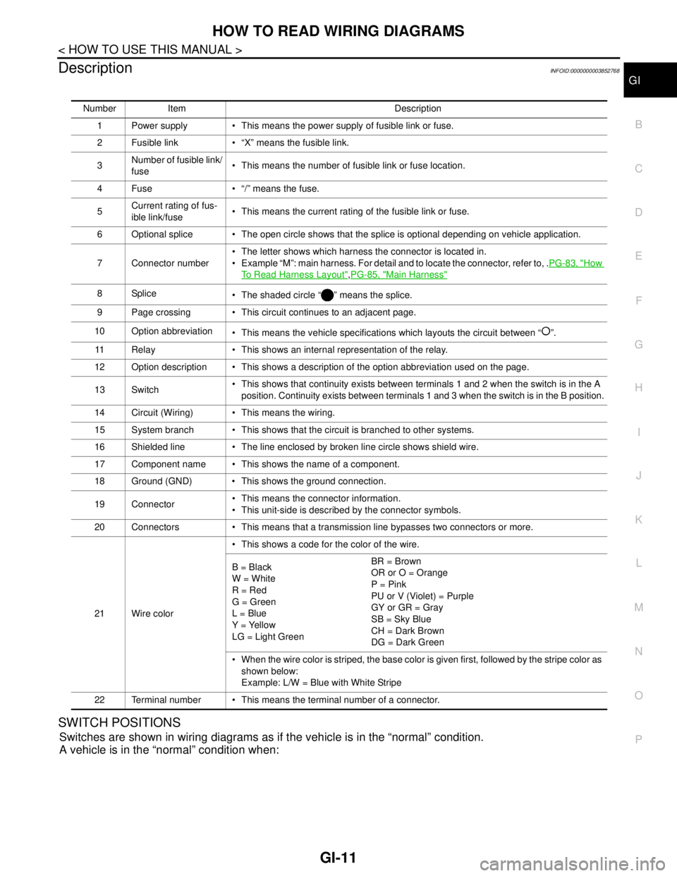
Number Item Description
1 Power supply This means the power supply of fusible link or fuse.
2 Fusible link “X” means the fusible link.
3Number of fusible link/
fuse This means the number of fusible link or fuse location.
4 Fuse “/” means the fuse.
5Current rating of fus-
ible link/fuse This means the current rating of the fusible link or fuse.
6 Optional splice The open circle shows that the splice is optional depending on vehicle application.
7 Connector number The letter shows which harness the connector is located in.
Example “M”: main harness. For detail and to locate the connector, refer to, .PG-83, "
How
To Read Harness Layout",PG-85, "Main Harness"
8Splice
The shaded circle “ ” means the splice.
9 Page crossing This circuit continues to an adjacent page.
10 Option abbreviation
This means the vehicle specifications which layouts the circuit between “ ”.
11 Relay This shows an internal representation of the relay.
12 Option description This shows a description of the option abbreviation used on the page.
13 Switch This shows that continuity exists between terminals 1 and 2 when the switch is in the A
position. Continuity exists between terminals 1 and 3 when the switch is in the B position.
14 Circuit (Wiring) This means the wiring.
15 System branch This shows that the circuit is branched to other systems.
16 Shielded line The line enclosed by broken line circle shows shield wire.
17 Component name This shows the name of a component.
18 Ground (GND) This shows the ground connection.
19 Connector This means the connector information.
This unit-side is described by the connector symbols.
20 Connectors This means that a transmission line bypasses two connectors or more.
21 Wire color This shows a code for the color of the wire.
B = Black
W = White
R = Red
G = Green
L = Blue
Y = Yellow
LG = Light GreenBR = Brown
OR or O = Orange
P = Pink
PU or V (Violet) = Purple
GY or GR = Gray
SB = Sky Blue
CH = Dark Brown
DG = Dark Green
When the wire color is striped, the base color is given first, followed by the stripe color as
shown below:
Example: L/W = Blue with White Stripe
22 Terminal number This means the terminal number of a connector.
Page 2529 of 5121
GI-36
< BASIC INSPECTION >
SERVICE INFORMATION FOR ELECTRICAL INCIDENT
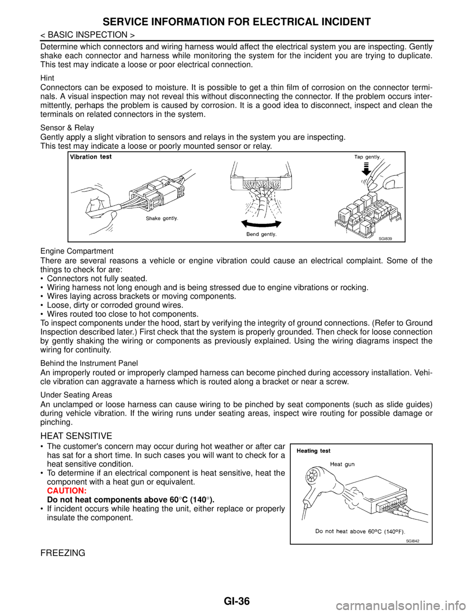
Determine which connectors and wiring harness would affect the electrical system you are inspecting. Gently
shake each connector and harness while monitoring the system for the incident you are trying to duplicate.
This test may indicate a loose or poor electrical connection.
Hint
Connectors can be exposed to moisture. It is possible to get a thin film of corrosion on the connector termi-
nals. A visual inspection may not reveal this without disconnecting the connector. If the problem occurs inter-
mittently, perhaps the problem is caused by corrosion. It is a good idea to disconnect, inspect and clean the
terminals on related connectors in the system.
Sensor & Relay
Gently apply a slight vibration to sensors and relays in the system you are inspecting.
This test may indicate a loose or poorly mounted sensor or relay.
Engine Compartment
There are several reasons a vehicle or engine vibration could cause an electrical complaint. Some of the
things to check for are:
Connectors not fully seated.
Wiring harness not long enough and is being stressed due to engine vibrations or rocking.
Wires laying across brackets or moving components.
Loose, dirty or corroded ground wires.
Wires routed too close to hot components.
To inspect components under the hood, start by verifying the integrity of ground connections. (Refer to Ground
Inspection described later.) First check that the system is properly grounded. Then check for loose connection
by gently shaking the wiring or components as previously explained. Using the wiring diagrams inspect the
wiring for continuity.
Behind the Instrument Panel
An improperly routed or improperly clamped harness can become pinched during accessory installation. Vehi-
cle vibration can aggravate a harness which is routed along a bracket or near a screw.
Under Seating Areas
An unclamped or loose harness can cause wiring to be pinched by seat components (such as slide guides)
during vehicle vibration. If the wiring runs under seating areas, inspect wire routing for possible damage or
pinching.
HEAT SENSITIVE
The customer's concern may occur during hot weather or after car
has sat for a short time. In such cases you will want to check for a
heat sensitive condition.
To determine if an electrical component is heat sensitive, heat the
component with a heat gun or equivalent.
CAUTION:
Do not heat components above 60°C (140°).
If incident occurs while heating the unit, either replace or properly
insulate the component.
FREEZING
SGI839
SGI842
Page 2531 of 5121
GI-38
< BASIC INSPECTION >
SERVICE INFORMATION FOR ELECTRICAL INCIDENT
TESTING FOR “OPENS” IN THE CIRCUIT
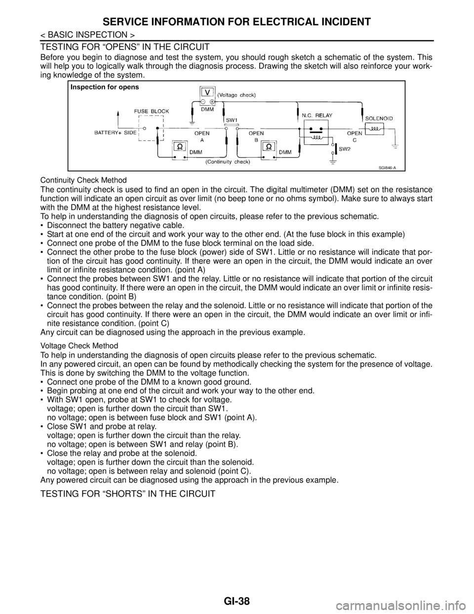
Before you begin to diagnose and test the system, you should rough sketch a schematic of the system. This
will help you to logically walk through the diagnosis process. Drawing the sketch will also reinforce your work-
ing knowledge of the system.
Continuity Check Method
The continuity check is used to find an open in the circuit. The digital multimeter (DMM) set on the resistance
function will indicate an open circuit as over limit (no beep tone or no ohms symbol). Make sure to always start
with the DMM at the highest resistance level.
To help in understanding the diagnosis of open circuits, please refer to the previous schematic.
Disconnect the battery negative cable.
Start at one end of the circuit and work your way to the other end. (At the fuse block in this example)
Connect one probe of the DMM to the fuse block terminal on the load side.
Connect the other probe to the fuse block (power) side of SW1. Little or no resistance will indicate that por-
tion of the circuit has good continuity. If there were an open in the circuit, the DMM would indicate an over
limit or infinite resistance condition. (point A)
Connect the probes between SW1 and the relay. Little or no resistance will indicate that portion of the circuit
has good continuity. If there were an open in the circuit, the DMM would indicate an over limit or infinite resis-
tance condition. (point B)
Connect the probes between the relay and the solenoid. Little or no resistance will indicate that portion of the
circuit has good continuity. If there were an open in the circuit, the DMM would indicate an over limit or infi-
nite resistance condition. (point C)
Any circuit can be diagnosed using the approach in the previous example.
Voltage Check Method
To help in understanding the diagnosis of open circuits please refer to the previous schematic.
In any powered circuit, an open can be found by methodically checking the system for the presence of voltage.
This is done by switching the DMM to the voltage function.
Connect one probe of the DMM to a known good ground.
Begin probing at one end of the circuit and work your way to the other end.
With SW1 open, probe at SW1 to check for voltage.
voltage; open is further down the circuit than SW1.
no voltage; open is between fuse block and SW1 (point A).
Close SW1 and probe at relay.
voltage; open is further down the circuit than the relay.
no voltage; open is between SW1 and relay (point B).
Close the relay and probe at the solenoid.
voltage; open is further down the circuit than the solenoid.
no voltage; open is between relay and solenoid (point C).
Any powered circuit can be diagnosed using the approach in the previous example.
TESTING FOR “SHORTS” IN THE CIRCUIT
SGI846-A
Page 2532 of 5121
SERVICE INFORMATION FOR ELECTRICAL INCIDENT
GI-39
< BASIC INSPECTION >
C
D
E
F
G
H
I
J
K
L
MB
GI
N
O
P
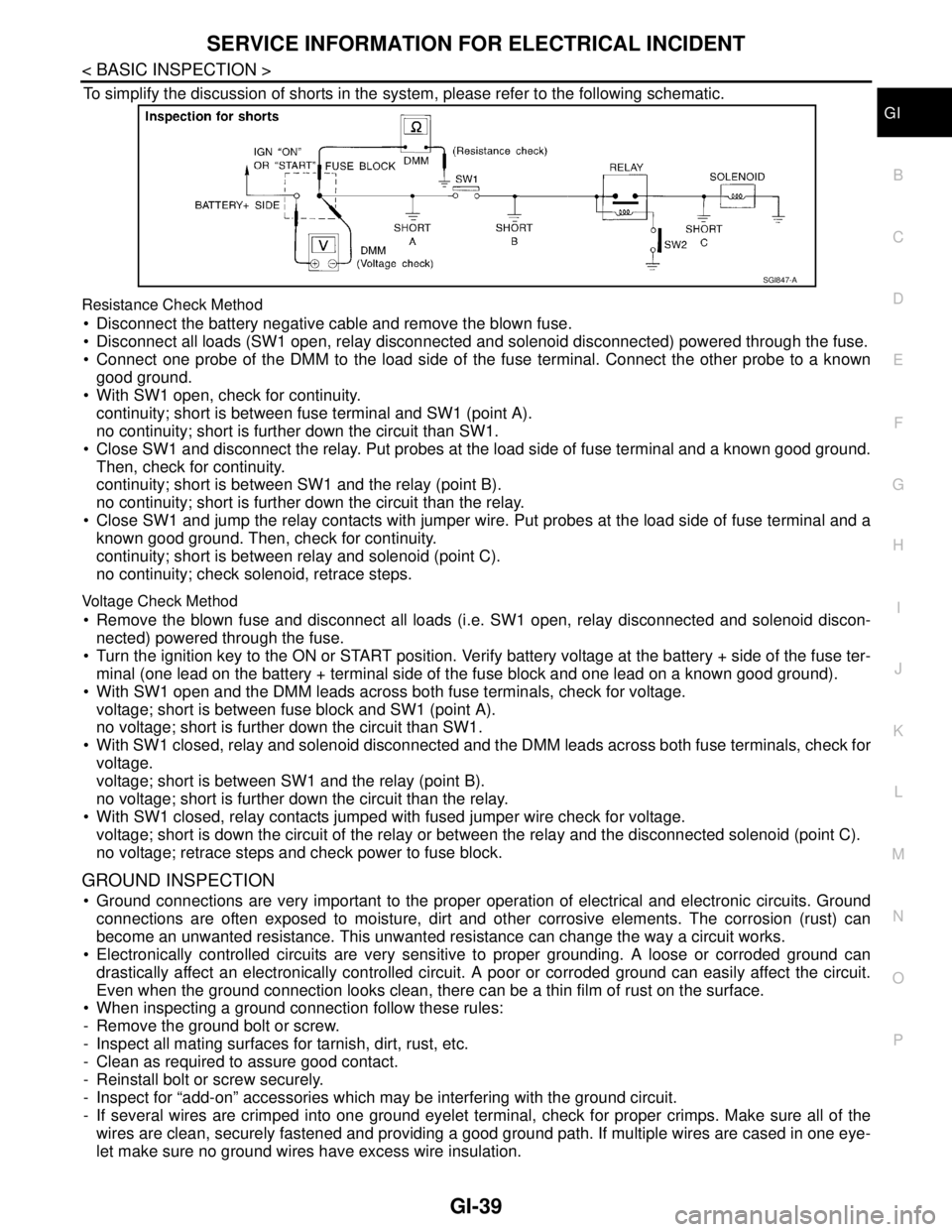
To simplify the discussion of shorts in the system, please refer to the following schematic.
Resistance Check Method
Disconnect the battery negative cable and remove the blown fuse.
Disconnect all loads (SW1 open, relay disconnected and solenoid disconnected) powered through the fuse.
Connect one probe of the DMM to the load side of the fuse terminal. Connect the other probe to a known
good ground.
With SW1 open, check for continuity.
continuity; short is between fuse terminal and SW1 (point A).
no continuity; short is further down the circuit than SW1.
Close SW1 and disconnect the relay. Put probes at the load side of fuse terminal and a known good ground.
Then, check for continuity.
continuity; short is between SW1 and the relay (point B).
no continuity; short is further down the circuit than the relay.
Close SW1 and jump the relay contacts with jumper wire. Put probes at the load side of fuse terminal and a
known good ground. Then, check for continuity.
continuity; short is between relay and solenoid (point C).
no continuity; check solenoid, retrace steps.
Voltage Check Method
Remove the blown fuse and disconnect all loads (i.e. SW1 open, relay disconnected and solenoid discon-
nected) powered through the fuse.
Turn the ignition key to the ON or START position. Verify battery voltage at the battery + side of the fuse ter-
minal (one lead on the battery + terminal side of the fuse block and one lead on a known good ground).
With SW1 open and the DMM leads across both fuse terminals, check for voltage.
voltage; short is between fuse block and SW1 (point A).
no voltage; short is further down the circuit than SW1.
With SW1 closed, relay and solenoid disconnected and the DMM leads across both fuse terminals, check for
voltage.
voltage; short is between SW1 and the relay (point B).
no voltage; short is further down the circuit than the relay.
With SW1 closed, relay contacts jumped with fused jumper wire check for voltage.
voltage; short is down the circuit of the relay or between the relay and the disconnected solenoid (point C).
no voltage; retrace steps and check power to fuse block.
GROUND INSPECTION
Ground connections are very important to the proper operation of electrical and electronic circuits. Ground
connections are often exposed to moisture, dirt and other corrosive elements. The corrosion (rust) can
become an unwanted resistance. This unwanted resistance can change the way a circuit works.
Electronically controlled circuits are very sensitive to proper grounding. A loose or corroded ground can
drastically affect an electronically controlled circuit. A poor or corroded ground can easily affect the circuit.
Even when the ground connection looks clean, there can be a thin film of rust on the surface.
When inspecting a ground connection follow these rules:
- Remove the ground bolt or screw.
- Inspect all mating surfaces for tarnish, dirt, rust, etc.
- Clean as required to assure good contact.
- Reinstall bolt or screw securely.
- Inspect for “add-on” accessories which may be interfering with the ground circuit.
- If several wires are crimped into one ground eyelet terminal, check for proper crimps. Make sure all of the
wires are clean, securely fastened and providing a good ground path. If multiple wires are cased in one eye-
let make sure no ground wires have excess wire insulation.
SGI847-A
Page 2574 of 5121
REFRIGERATION SYSTEM
HA-5
< FUNCTION DIAGNOSIS >
C
D
E
F
G
H
J
K
L
MA
B
HA
N
O
P
FUNCTION DIAGNOSIS
REFRIGERATION SYSTEM
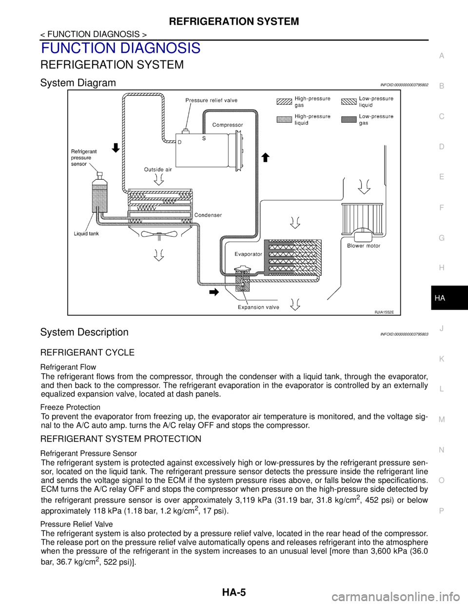
System DiagramINFOID:0000000003795802
System DescriptionINFOID:0000000003795803
REFRIGERANT CYCLE
Refrigerant Flow
The refrigerant flows from the compressor, through the condenser with a liquid tank, through the evaporator,
and then back to the compressor. The refrigerant evaporation in the evaporator is controlled by an externally
equalized expansion valve, located at dash panels.
Freeze Protection
To prevent the evaporator from freezing up, the evaporator air temperature is monitored, and the voltage sig-
nal to the A/C auto amp. turns the A/C relay OFF and stops the compressor.
REFRIGERANT SYSTEM PROTECTION
Refrigerant Pressure Sensor
The refrigerant system is protected against excessively high or low-pressures by the refrigerant pressure sen-
sor, located on the liquid tank. The refrigerant pressure sensor detects the pressure inside the refrigerant line
and sends the voltage signal to the ECM if the system pressure rises above, or falls below the specifications.
ECM turns the A/C relay OFF and stops the compressor when pressure on the high-pressure side detected by
the refrigerant pressure sensor is over approximately 3,119 kPa (31.19 bar, 31.8 kg/cm
2, 452 psi) or below
approximately 118 kPa (1.18 bar, 1.2 kg/cm
2, 17 psi).
Pressure Relief Valve
The refrigerant system is also protected by a pressure relief valve, located in the rear head of the compressor.
The release port on the pressure relief valve automatically opens and releases refrigerant into the atmosphere
when the pressure of the refrigerant in the system increases to an unusual level [more than 3,600 kPa (36.0
bar, 36.7 kg/cm
2, 522 psi)].
RJIA1552E