Page 1945 of 5121

EM-70
< REMOVAL AND INSTALLATION >
ENGINE ASSEMBLY
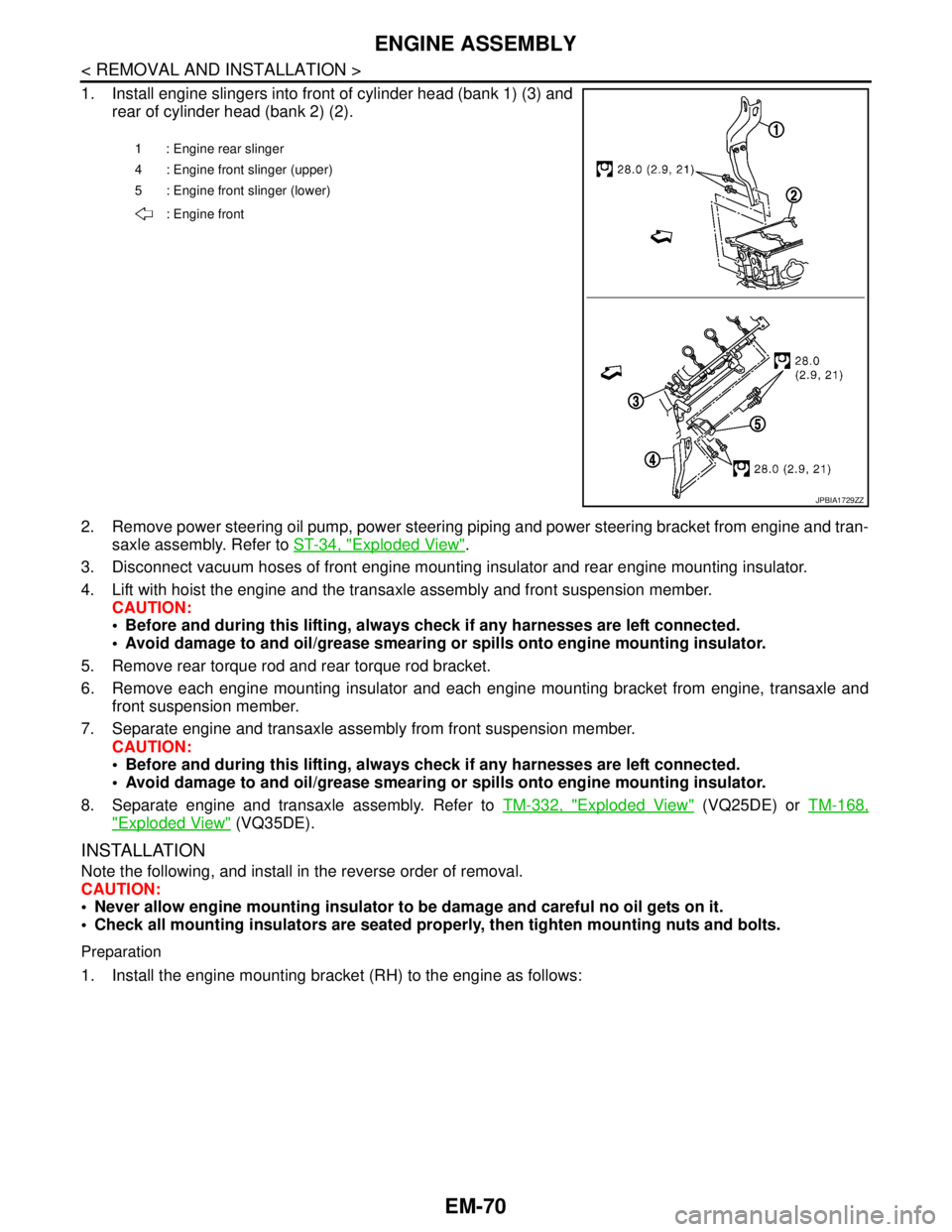
1. Install engine slingers into front of cylinder head (bank 1) (3) and
rear of cylinder head (bank 2) (2).
2. Remove power steering oil pump, power steering piping and power steering bracket from engine and tran-
saxle assembly. Refer to ST-34, "
Exploded View".
3. Disconnect vacuum hoses of front engine mounting insulator and rear engine mounting insulator.
4. Lift with hoist the engine and the transaxle assembly and front suspension member.
CAUTION:
Before and during this lifting, always check if any harnesses are left connected.
Avoid damage to and oil/grease smearing or spills onto engine mounting insulator.
5. Remove rear torque rod and rear torque rod bracket.
6. Remove each engine mounting insulator and each engine mounting bracket from engine, transaxle and
front suspension member.
7. Separate engine and transaxle assembly from front suspension member.
CAUTION:
Before and during this lifting, always check if any harnesses are left connected.
Avoid damage to and oil/grease smearing or spills onto engine mounting insulator.
8. Separate engine and transaxle assembly. Refer to TM-332, "
Exploded View" (VQ25DE) or TM-168,
"Exploded View" (VQ35DE).
INSTALLATION
Note the following, and install in the reverse order of removal.
CAUTION:
Never allow engine mounting insulator to be damage and careful no oil gets on it.
Check all mounting insulators are seated properly, then tighten mounting nuts and bolts.
Preparation
1. Install the engine mounting bracket (RH) to the engine as follows:
1 : Engine rear slinger
4 : Engine front slinger (upper)
5 : Engine front slinger (lower)
: Engine front
JPBIA1729ZZ
Page 1947 of 5121
EM-72
< REMOVAL AND INSTALLATION >
ENGINE ASSEMBLY
VQ25DE
VQ35DE
5. Install the engine mounting insulator (LH) to the transaxle as follows:
a. Tighten the bolt No. 3 as shown in the figure. (temporarily)
b. Tighten the bolts in numerical order as shown in the figure. (specified torque)
VQ25DE
VQ35DE
6. Install the engine mounting insulator (front) to the front suspension member as follows:
: Engine front
JPBIA2376ZZ
: Engine front
JPBIA2377ZZ
: Vehicle front
JPBIA2196ZZ
: Vehicle front
JPBIA1734ZZ
Page 1948 of 5121

ENGINE ASSEMBLY
EM-73
< REMOVAL AND INSTALLATION >
C
D
E
F
G
H
I
J
K
L
MA
EM
N
P O
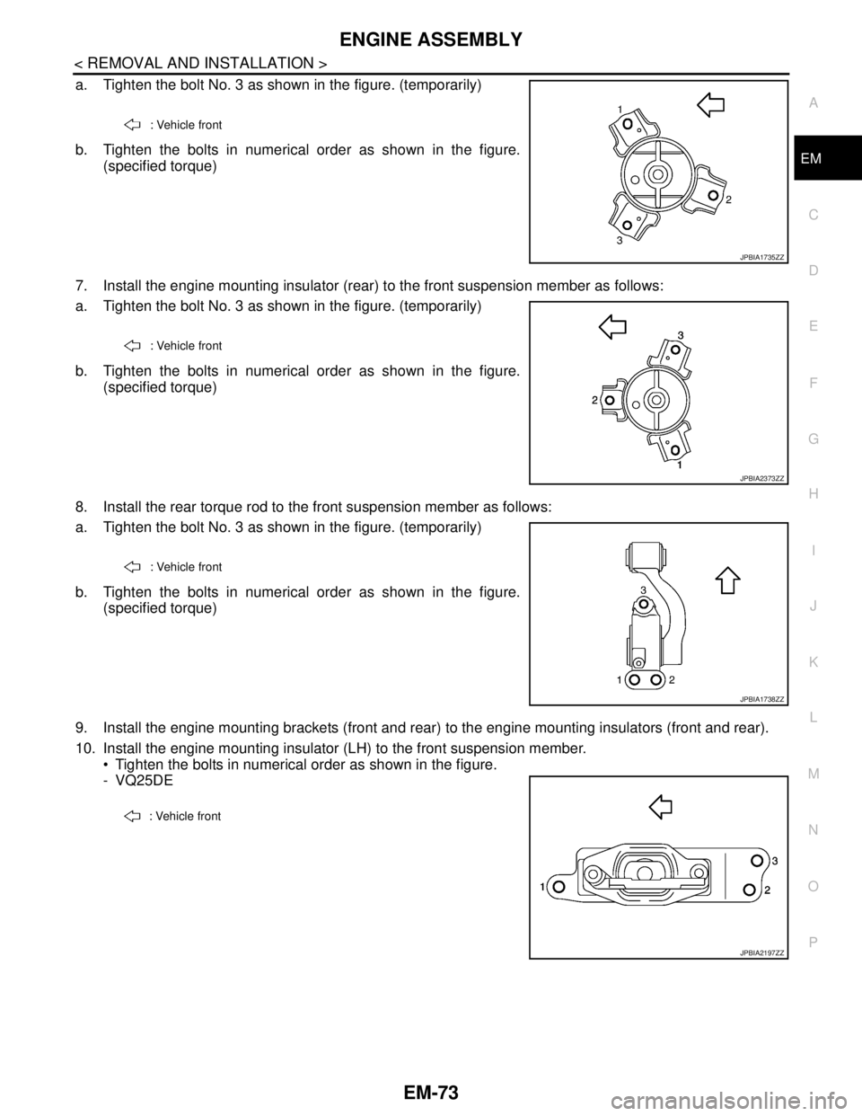
a. Tighten the bolt No. 3 as shown in the figure. (temporarily)
b. Tighten the bolts in numerical order as shown in the figure.
(specified torque)
7. Install the engine mounting insulator (rear) to the front suspension member as follows:
a. Tighten the bolt No. 3 as shown in the figure. (temporarily)
b. Tighten the bolts in numerical order as shown in the figure.
(specified torque)
8. Install the rear torque rod to the front suspension member as follows:
a. Tighten the bolt No. 3 as shown in the figure. (temporarily)
b. Tighten the bolts in numerical order as shown in the figure.
(specified torque)
9. Install the engine mounting brackets (front and rear) to the engine mounting insulators (front and rear).
10. Install the engine mounting insulator (LH) to the front suspension member.
Tighten the bolts in numerical order as shown in the figure.
- VQ25DE
: Vehicle front
JPBIA1735ZZ
: Vehicle front
JPBIA2373ZZ
: Vehicle front
JPBIA1738ZZ
: Vehicle front
JPBIA2197ZZ
Page 2044 of 5121
![NISSAN TEANA 2008 Service Manual HEADLAMP AIMING CONTROL SYSTEM (AUTO)
EXL-15
< FUNCTION DIAGNOSIS >[XENON TYPE]
C
D
E
F
G
H
I
J
K
MA
B
EXL
N
O
P
HEADLAMP AIMING CONTROL SYSTEM (AUTO)
System DiagramINFOID:0000000003774320
System Desc NISSAN TEANA 2008 Service Manual HEADLAMP AIMING CONTROL SYSTEM (AUTO)
EXL-15
< FUNCTION DIAGNOSIS >[XENON TYPE]
C
D
E
F
G
H
I
J
K
MA
B
EXL
N
O
P
HEADLAMP AIMING CONTROL SYSTEM (AUTO)
System DiagramINFOID:0000000003774320
System Desc](/manual-img/5/57391/w960_57391-2043.png)
HEADLAMP AIMING CONTROL SYSTEM (AUTO)
EXL-15
< FUNCTION DIAGNOSIS >[XENON TYPE]
C
D
E
F
G
H
I
J
K
MA
B
EXL
N
O
P
HEADLAMP AIMING CONTROL SYSTEM (AUTO)
System DiagramINFOID:0000000003774320
System DescriptionINFOID:0000000003774321
OUTLINE
Headlamp aiming control system is controlled by auto levelizer control unit.
Auto levelizer control unit controls the headlamp light axis height appropriately depending on the vehicle rear
height.
Auto levelizer control unit detects the vehicle condition necessary for the aiming motor control with the fol-
lowing signals.
- Sensor lever signal (detected by the sensor lever)
- Tail lamp signal (inputted from IPDM E/R)
- Vehicle speed signal (8-pulse) (inputted from combination meter)
HEADLAMP AUTO AIMING OPERATION
Auto levelizer control unit calculates vehicle pitch angle from sensor lever signal and determines the neces-
sary correction to compensate the deviation from standard light axis position.
Auto levelizer control unit outputs aiming motor drive signal when operating conditions are satisfied.
Operating condition
- Ignition switch ON
- Tail lamp ON
Auto levelizer control unit changes the aiming motor drive signal when any of the correcting condition is
detected. Output is maintained if other condition is detected.
Correcting condition- Tail lamp is turned ON.
- Vehicle posture becomes stable after the vehicle posture change is detected with the tail lamp ON and the
vehicle stopped.
- Vehicle speed is maintained with the tail lamp ON and the vehicle driven.
CAUTION:
Adjusted axis position may differ from the preset position although the headlamp auto aiming acti-
vates properly when the suspension is replaced or worn.
JPLIA0171GB
Page 2045 of 5121
EXL-16
< FUNCTION DIAGNOSIS >[XENON TYPE]
HEADLAMP AIMING CONTROL SYSTEM (AUTO)
Component Parts Location
INFOID:0000000003774322
Component DescriptionINFOID:0000000003774323
1. Combination meter 2. Aiming motor 3. IPDM E/R
4. Auto levelizer control unit
A. Front combination lamp (back) B. Engine room (LH) C. Left rear suspension member
JPLIA1148ZZ
Part Description
Auto levelizer control unit Refer to EXL-60, "
Description".
Headlamp aiming motor Refer to EXL-60, "
Description".
IPDM E/R Outputs the tail lamp signal to auto levelizer control unit.
Combination meter Outputs the vehicle speed signal (8-pulse) to auto levelizer control unit.
Page 2067 of 5121
EXL-38
< COMPONENT DIAGNOSIS >[XENON TYPE]
B2080 ECU TROUBLE
COMPONENT DIAGNOSIS
B2080 ECU TROUBLE
DescriptionINFOID:0000000003805599
Auto levelizer control unit is installed in rear suspension arm.
Auto levelizer control unit detects vehicle rear height.
Auto levelizer control unit controls headlamp light axis appropriately depending on the vehicle height.
DTC LogicINFOID:0000000003805600
DTC DETECTION LOGIC
[B2080] ECU TROUBLE
Diagnosis ProcedureINFOID:0000000003805601
1.ERASE DTC
Erase DTC memory of HEADLAMP LEVELIZER with self-diagnosis of CONSULT-III.
Is the memory erased?
YES >> INSPECTION END
NO >> Replace the auto levelizer control unit.
DTC detection condition DTC erase conditions Possible causes
Auto levelizer control unit internal malfunction. Ignition switch OFF Auto levelizer control unit
Page 2430 of 5121
FAX-2
< SYMPTOM DIAGNOSIS >
NOISE, VIBRATION AND HARSHNESS (NVH) TROUBLESHOOTING
SYMPTOM DIAGNOSIS
NOISE, VIBRATION AND HARSHNESS (NVH) TROUBLESHOOTING
NVH Troubleshooting ChartINFOID:0000000003811068
Use chart below to find the cause of the symptom. If necessary, repair or replace these parts.
×: ApplicableReference page
—
FAX-33—
FAX-8—
FAX-6
NVH in FAX and FSU sections
Refer to Front axle in this chart
NVH in WT section
NVH in WT section
Refer to DRIVE SHAFT in this chart
NVH in BR section
NVH in ST section
Possible cause and SUSPECTED PARTS
Excessive joint angle
Joint sliding resistance
Imbalance
Improper installation, looseness
Parts interference
Wheel bearing damage
FRONT AXLE AND FRONT SUSPENSION
FRONT AXLE
TIRE
ROAD WHEEL
DRIVE SHAFT
BRAKE
STEERING
SymptomDRIVE
SHAFTNoise×× ××××× ××
Shake× × ××××× ××
FRONT
AXLENoise×××× ×××××
Shake×××× ×××××
Vibration×××× × × ×
Shimmy×× × ×× ××
Judder× × ×× ××
Poor quality ride or handling×× × ××
Page 2447 of 5121

FRONT DRIVE SHAFT
FAX-19
< ON-VEHICLE REPAIR >
C
E
F
G
H
I
J
K
L
MA
B
FA X
N
O
P
Place the protector (A) (SST: KV38107900) onto transaxle assem-
bly to prevent damage to the oil seal while inserting drive shaft.
Slide drive shaft sliding joint and tap with a hammer to install
securely.
CAUTION:
Make sure that circular clip is completely engaged.
Never reuse cotter pin.
RIGHT SIDE
RIGHT SIDE : Removal and InstallationINFOID:0000000003811085
REMOVAL
1. Remove tires.
2. Remove wheel sensor and sensor harness. Refer to BRC-57, "
FRONT WHEEL SENSOR : Exploded
View" (without VDC), BRC-151, "FRONT WHEEL SENSOR : Exploded View" (with VDC).
3. Remove lock plate of brake hose from strut assembly. Refer to BR-19, "
FRONT : Exploded View".
4. Remove caliper assembly. Hang caliper assembly not to interfere with work. Refer to BR-34, "
BRAKE
CALIPER ASSEMBLY : Exploded View".
5. Remove disc rotor. Refer to BR-35, "
BRAKE CALIPER ASSEMBLY : Removal and Installation".
6. Remove cotter pin, and then loosen wheel hub lock nut. Refer to FA X - 8 , "
Exploded View".
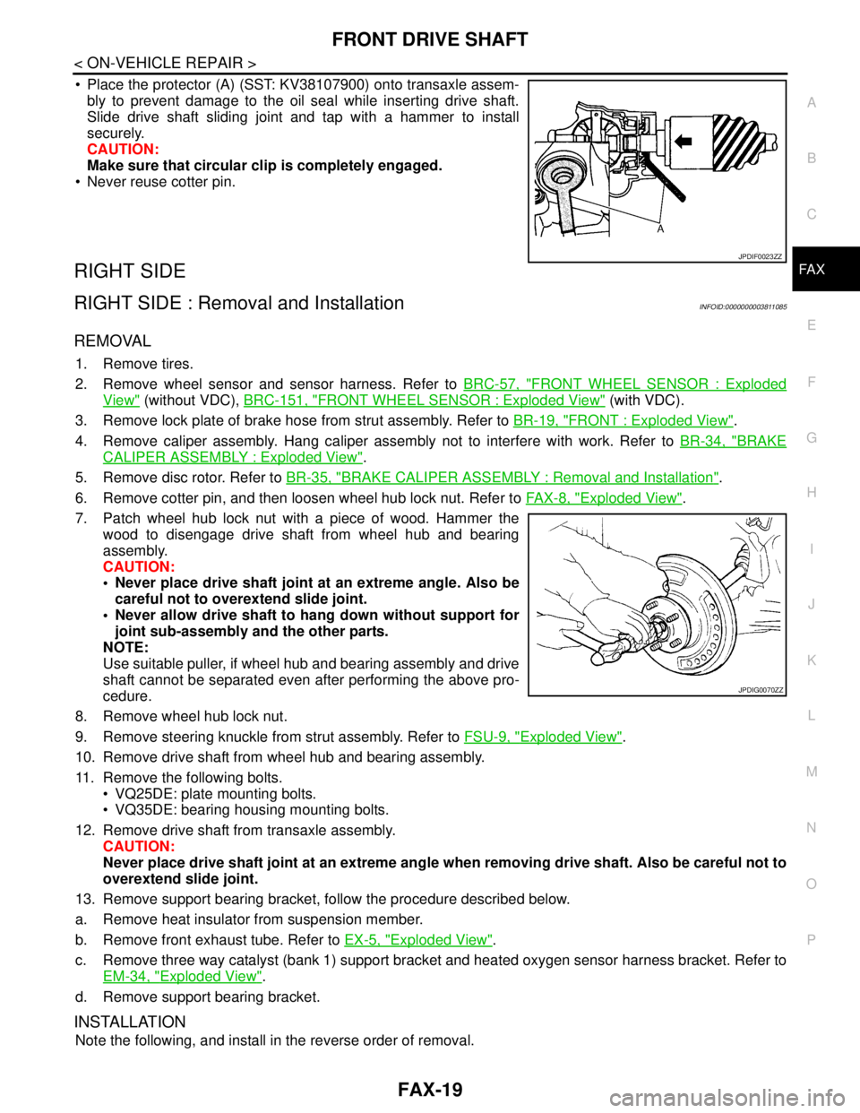
7. Patch wheel hub lock nut with a piece of wood. Hammer the
wood to disengage drive shaft from wheel hub and bearing
assembly.
CAUTION:
Never place drive shaft joint at an extreme angle. Also be
careful not to overextend slide joint.
Never allow drive shaft to hang down without support for
joint sub-assembly and the other parts.
NOTE:
Use suitable puller, if wheel hub and bearing assembly and drive
shaft cannot be separated even after performing the above pro-
cedure.
8. Remove wheel hub lock nut.
9. Remove steering knuckle from strut assembly. Refer to FSU-9, "
Exploded View".
10. Remove drive shaft from wheel hub and bearing assembly.
11. Remove the following bolts.
VQ25DE: plate mounting bolts.
VQ35DE: bearing housing mounting bolts.
12. Remove drive shaft from transaxle assembly.
CAUTION:
Never place drive shaft joint at an extreme angle when removing drive shaft. Also be careful not to
overextend slide joint.
13. Remove support bearing bracket, follow the procedure described below.
a. Remove heat insulator from suspension member.
b. Remove front exhaust tube. Refer to EX-5, "
Exploded View".
c. Remove three way catalyst (bank 1) support bracket and heated oxygen sensor harness bracket. Refer to
EM-34, "
Exploded View".
d. Remove support bearing bracket.
INSTALLATION
Note the following, and install in the reverse order of removal.
JPDIF0023ZZ
JPDIG0070ZZ