2008 NISSAN TEANA suspension
[x] Cancel search: suspensionPage 2475 of 5121
FSU-1
SUSPENSION
C
DF
G H
I
J
K L
M
SECTION FSU
A
B
FSU
N
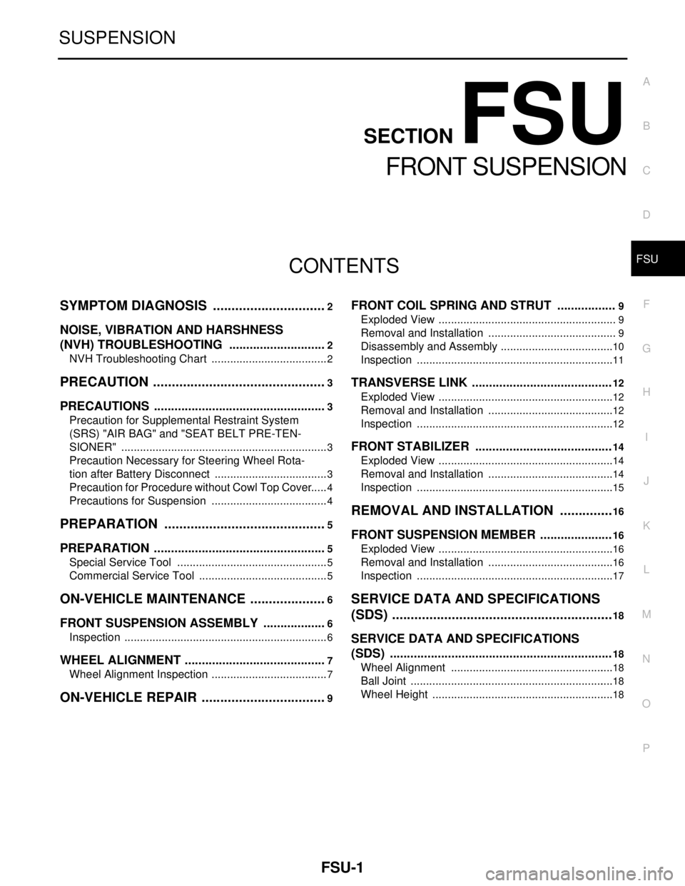
O PCONTENTS
FRONT SUSPENSION
SYMPTOM DIAGNOSIS ..... ..........................2
NOISE, VIBRATION AND HARSHNESS
(NVH) TROUBLESHOOTING ........................ .....
2
NVH Troubleshooting Chart ................................ ......2
PRECAUTION ...............................................3
PRECAUTIONS .............................................. .....3
Precaution for Supplemental Restraint System
(SRS) "AIR BAG" and "SEAT BELT PRE-TEN-
SIONER" ............................................................. ......
3
Precaution Necessary for Steering Wheel Rota-
tion after Battery Disconnect .....................................
3
Precaution for Procedure without Cowl Top Cover ......4
Precautions for Suspension ......................................4
PREPARATION ............................................5
PREPARATION .............................................. .....5
Special Service Tool ........................................... ......5
Commercial Service Tool ..........................................5
ON-VEHICLE MAINTENANCE .....................6
FRONT SUSPENSION ASSEMBLY .............. .....6
Inspection ............................................................ ......6
WHEEL ALIGNMENT ..........................................7
Wheel Alignment Inspection ................................ ......7
ON-VEHICLE REPAIR ..................................9
FRONT COIL SPRING AND STRUT .................9
Exploded View ..................................................... .....9
Removal and Installation ..........................................9
Disassembly and Assembly .....................................10
Inspection ................................................................11
TRANSVERSE LINK .........................................12
Exploded View ..................................................... ....12
Removal and Installation .........................................12
Inspection ................................................................12
FRONT STABILIZER ........................................14
Exploded View .........................................................14
Removal and Installation .........................................14
Inspection ................................................................15
REMOVAL AND INSTALLATION ...............16
FRONT SUSPENSION MEMBER .....................16
Exploded View ..................................................... ....16
Removal and Installation .........................................16
Inspection ................................................................17
SERVICE DATA AND SPECIFICATIONS
(SDS) ............... .............................................
18
SERVICE DATA AND SPECIFICATIONS
(SDS) .................................................................
18
Wheel Alignment ................................................. ....18
Ball Joint ..................................................................18
Wheel Height ...........................................................18
Page 2476 of 5121
FSU-2
< SYMPTOM DIAGNOSIS >
NOISE, VIBRATION AND HARSHNESS (NVH) TROUBLESHOOTING
SYMPTOM DIAGNOSIS
NOISE, VIBRATION AND HARSHNESS (NVH) TROUBLESHOOTING
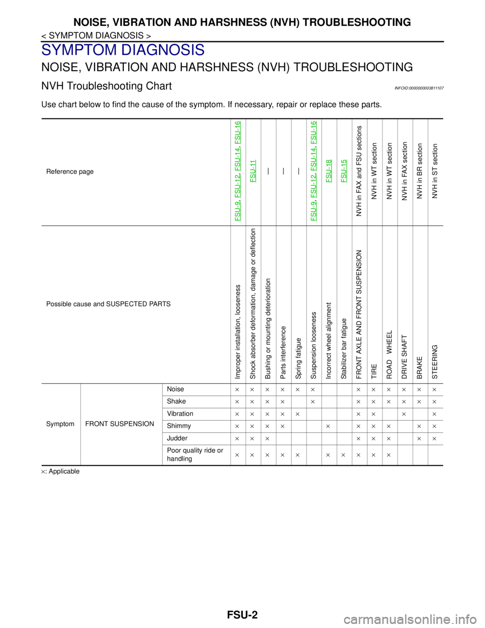
NVH Troubleshooting ChartINFOID:0000000003811107
Use chart below to find the cause of the symptom. If necessary, repair or replace these parts.
×: ApplicableReference page
FSU-9
, FSU-12
, FSU-14
, FSU-16
FSU-11
—
—
—
FSU-9
, FSU-12
, FSU-14
, FSU-16
FSU-18FSU-15
NVH in FAX and FSU sections
NVH in WT section
NVH in WT section
NVH in FAX section
NVH in BR section
NVH in ST section
Possible cause and SUSPECTED PARTS
Improper installation, looseness
Shock absorber deformation, damage or deflection
Bushing or mounting deterioration
Parts interference
Spring fatigue
Suspension looseness
Incorrect wheel alignment
Stabilizer bar fatigue
FRONT AXLE AND FRONT SUSPENSION
TIRE
ROAD WHEEL
DRIVE SHAFT
BRAKE
STEERING
Symptom FRONT SUSPENSIONNoise×××××× ××××××
Shake×××× × ××××××
Vibration××××× ×× × ×
Shimmy×××× × ××× ××
Judder ××× ××× ××
Poor quality ride or
handling××××× ×××××
Page 2478 of 5121
FSU-4
< PRECAUTION >
PRECAUTIONS
Precaution for Procedure without Cowl Top Cover
INFOID:0000000003890157
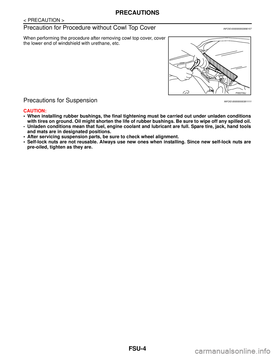
When performing the procedure after removing cowl top cover, cover
the lower end of windshield with urethane, etc.
Precautions for SuspensionINFOID:0000000003811111
CAUTION:
When installing rubber bushings, the final tightening must be carried out under unladen conditions
with tires on ground. Oil might shorten the life of rubber bushings. Be sure to wipe off any spilled oil.
- Unladen conditions mean that fuel, engine coolant and lubricant are full. Spare tire, jack, hand tools
and mats are in designated positions.
After servicing suspension parts, be sure to check wheel alignment.
Self-lock nuts are not reusable. Always use new ones when installing. Since new self-lock nuts are
pre-oiled, tighten as they are.
PIIB3706J
Page 2480 of 5121
FSU-6
< ON-VEHICLE MAINTENANCE >
FRONT SUSPENSION ASSEMBLY
ON-VEHICLE MAINTENANCE
FRONT SUSPENSION ASSEMBLY
InspectionINFOID:0000000003811114
MOUNTING INSPECTION
Make sure the mounting conditions (looseness, backlash) of each component and component conditions
(wear, damage) are normal.
BALL JOINT AXIAL END PLAY
1. Set front wheels in a straight-ahead position.
CAUTION:
Never depress brake pedal when measuring.
2. Place an iron bar or equivalent between transverse link and steering knuckle.
3. Measure axial end play by prying it up and down.
CAUTION:
Be careful not to damage ball joint boot. Never damage the installation position by applying exces-
sive force.
STRUT ASSEMBLY
Check for oil leakage and damage. Replace if necessary.Standard
Axial end play : Refer to FSU-18, "
Ball Joint".
Page 2481 of 5121
WHEEL ALIGNMENT
FSU-7
< ON-VEHICLE MAINTENANCE >
C
D
F
G
H
I
J
K
L
MA
B
FSU
N
O
P
WHEEL ALIGNMENT
Wheel Alignment InspectionINFOID:0000000003812473
INSPECTION
Description
CAUTION:
Camber, caster, kingpin inclination angles cannot be adjusted.
If camber, caster, or kingpin inclination angle exceeds the standard value, check front suspension
parts for wear and damage. Replace suspect parts if a malfunction is detected.
Kingpin inclination angle is reference value, no inspection is required.
Measure wheel alignment under unladen conditions.
NOTE:
“Unladen conditions” means that fuel, engine coolant, and lubricant are full. Spare tire, jack, hand tools and
mats are in designated positions.
Preliminary Check
Check the following:
Tires for improper air pressure and wear
Road wheels for runout: Refer to WT-2, "
Inspection".
Wheel bearing axial end play: Refer to FA X - 6 , "
Inspection".
Transverse link ball joint axial end play: Refer to FSU-11, "
Inspection".
Strut operation.
Each mounting part of axle and suspension for looseness and deformation
Each of suspension member and transverse link for cracks, deformation and other damage
Vehicle height (posture)
CAMBER, CASTER, AND KINGPIN INCLINATION ANGLES
Camber, caster, kingpin inclination angles cannot be adjusted.
Before inspection, mount front wheels onto turning radius gauge. Mount rear wheels onto a stand at the
same height so that vehicle remains horizontal.
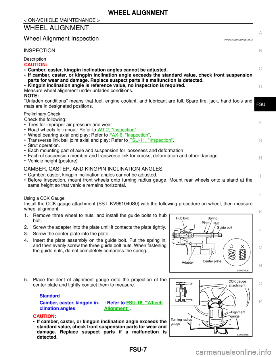
Using a CCK Gauge
Install the CCK gauge attachment (SST: KV991040S0) with the following procedure on wheel, then measure
wheel alignment.
1. Remove three wheel to nuts, and install the guide bolts to hub
bolt.
2. Screw the adapter into the plate until it contacts the plate tightly.
3. Screw the center plate into the plate.
4. Insert the plate assembly on the guide bolt. Put the spring in,
and then evenly screw the three guide bolt nuts. When fastening
the guide nuts, do not completely compress the spring.
5. Place the dent of alignment gauge onto the projection of the
center plate and tightly contact them to measure.
CAUTION:
If camber, caster, or kingpin inclination angle exceeds the
standard value, check front suspension parts for wear and
damage. Replace suspect parts if a malfunction is
detected.
SEIA0240E
Standard
Camber, caster, kingpin in-
clination angles: Refer to FSU-18, "
Wheel
Alignment".
SEIA0241E
Page 2486 of 5121
FSU-12
< ON-VEHICLE REPAIR >
TRANSVERSE LINK
TRANSVERSE LINK
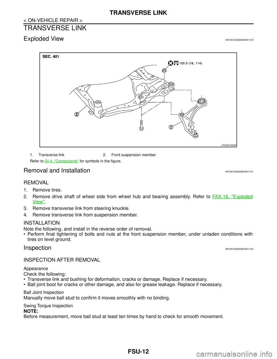
Exploded ViewINFOID:0000000003811120
Removal and InstallationINFOID:0000000003811121
REMOVAL
1. Remove tires.
2. Remove drive shaft of wheel side from wheel hub and bearing assembly. Refer to FAX-16, "
Exploded
View".
3. Remove transverse link from steering knuckle.
4. Remove transverse link from suspension member.
INSTALLATION
Note the following, and install in the reverse order of removal.
Perform final tightening of bolts and nuts at the front suspension member, under unladen conditions with
tires on level ground.
InspectionINFOID:0000000003811122
INSPECTION AFTER REMOVAL
Appearance
Check the following:
Transverse link and bushing for deformation, cracks or damage. Replace if necessary.
Ball joint boot for cracks or other damage, and also for grease leakage. Replace if necessary.
Ball Joint Inspection
Manually move ball stud to confirm it moves smoothly with no binding.
Swing Torque Inspection
NOTE:
Before measurement, move ball stud at least ten times by hand to check for smooth movement.
1. Transverse link 2. Front suspension member
Refer to GI-4, "
Components" for symbols in the figure.
JPEIA0100GB
Page 2488 of 5121
FSU-14
< ON-VEHICLE REPAIR >
FRONT STABILIZER
FRONT STABILIZER
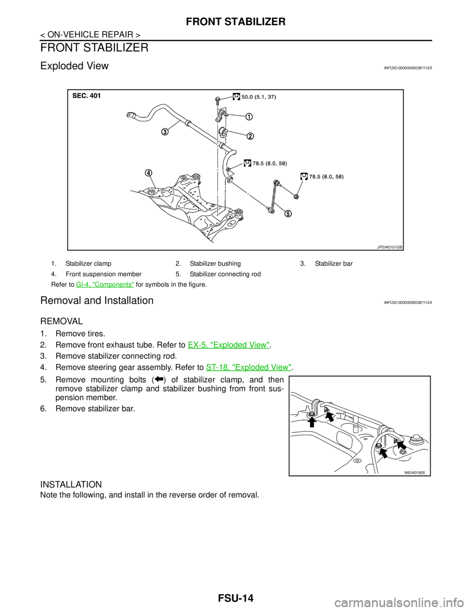
Exploded ViewINFOID:0000000003811123
Removal and InstallationINFOID:0000000003811124
REMOVAL
1. Remove tires.
2. Remove front exhaust tube. Refer to EX-5, "
Exploded View".
3. Remove stabilizer connecting rod.
4. Remove steering gear assembly. Refer to ST-18, "
Exploded View".
5. Remove mounting bolts ( ) of stabilizer clamp, and then
remove stabilizer clamp and stabilizer bushing from front sus-
pension member.
6. Remove stabilizer bar.
INSTALLATION
Note the following, and install in the reverse order of removal.
1. Stabilizer clamp 2. Stabilizer bushing 3. Stabilizer bar
4. Front suspension member 5. Stabilizer connecting rod
Refer to GI-4, "
Components" for symbols in the figure.
JPEIA0101GB
WEIA0182E
Page 2490 of 5121
FSU-16
< REMOVAL AND INSTALLATION >
FRONT SUSPENSION MEMBER
REMOVAL AND INSTALLATION
FRONT SUSPENSION MEMBER
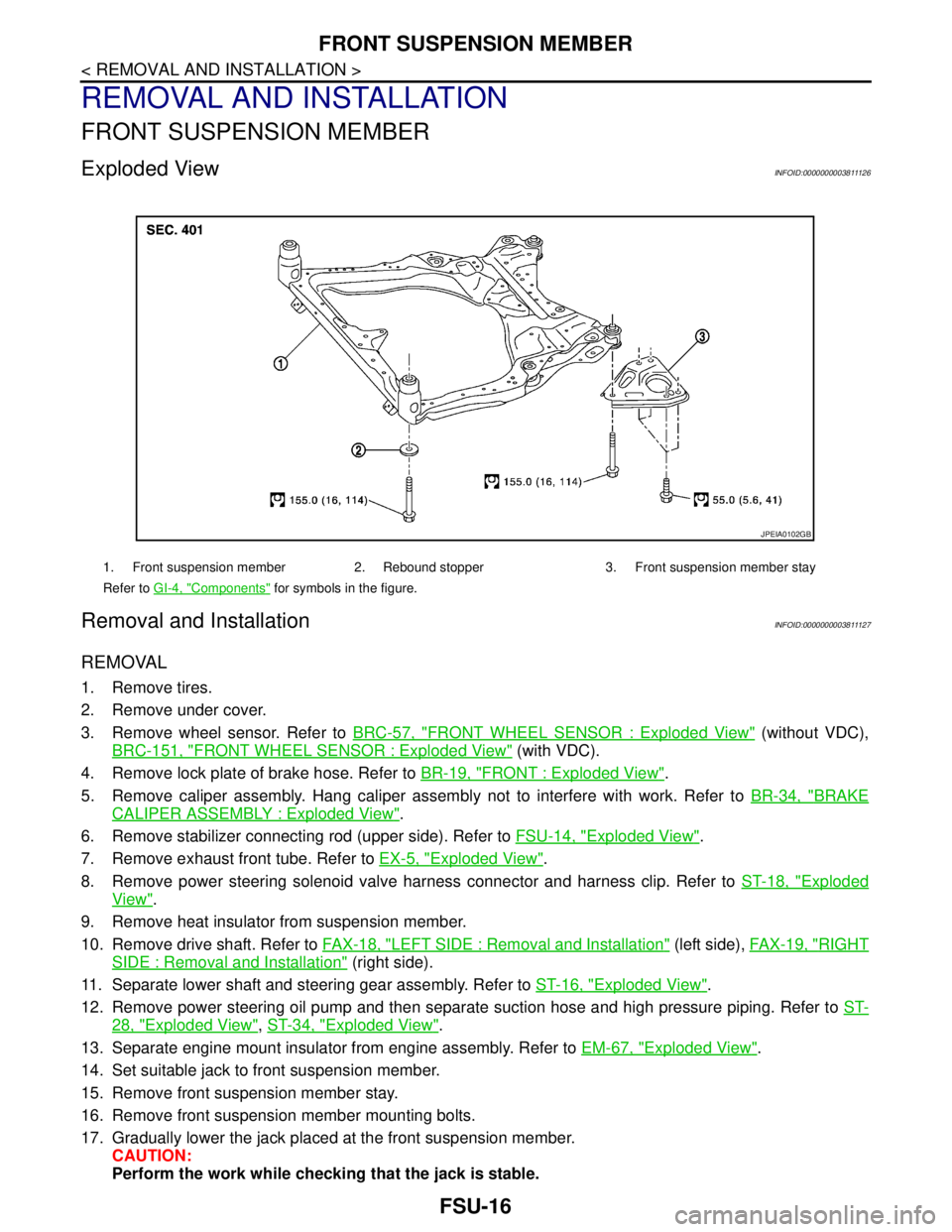
Exploded ViewINFOID:0000000003811126
Removal and InstallationINFOID:0000000003811127
REMOVAL
1. Remove tires.
2. Remove under cover.
3. Remove wheel sensor. Refer to BRC-57, "
FRONT WHEEL SENSOR : Exploded View" (without VDC),
BRC-151, "
FRONT WHEEL SENSOR : Exploded View" (with VDC).
4. Remove lock plate of brake hose. Refer to BR-19, "
FRONT : Exploded View".
5. Remove caliper assembly. Hang caliper assembly not to interfere with work. Refer to BR-34, "
BRAKE
CALIPER ASSEMBLY : Exploded View".
6. Remove stabilizer connecting rod (upper side). Refer to FSU-14, "
Exploded View".
7. Remove exhaust front tube. Refer to EX-5, "
Exploded View".
8. Remove power steering solenoid valve harness connector and harness clip. Refer to ST-18, "
Exploded
View".
9. Remove heat insulator from suspension member.
10. Remove drive shaft. Refer to FAX-18, "
LEFT SIDE : Removal and Installation" (left side), FAX-19, "RIGHT
SIDE : Removal and Installation" (right side).
11. Separate lower shaft and steering gear assembly. Refer to ST-16, "
Exploded View".
12. Remove power steering oil pump and then separate suction hose and high pressure piping. Refer to ST-
28, "Exploded View", ST-34, "Exploded View".
13. Separate engine mount insulator from engine assembly. Refer to EM-67, "
Exploded View".
14. Set suitable jack to front suspension member.
15. Remove front suspension member stay.
16. Remove front suspension member mounting bolts.
17. Gradually lower the jack placed at the front suspension member.
CAUTION:
Perform the work while checking that the jack is stable.
1. Front suspension member 2. Rebound stopper 3. Front suspension member stay
Refer to GI-4, "
Components" for symbols in the figure.
JPEIA0102GB