2008 NISSAN TEANA suspension
[x] Cancel search: suspensionPage 2491 of 5121
FRONT SUSPENSION MEMBER
FSU-17
< REMOVAL AND INSTALLATION >
C
D
F
G
H
I
J
K
L
MA
B
FSU
N
O
P
NOTE:
Remove the steering knuckle and wheel bearing assembly, steering gear assembly and hydraulic line,
stabilizer bar, transverse link and engine mounting insulator as a unit from the vehicle.
18. Remove the following parts.
Steering knuckle and wheel hub and bearing assembly: refer to FA X - 8 , "
Exploded View".
Steering gear assembly and hydraulic line: refer to ST-18, "
Exploded View" and ST-34, "Exploded
View".
Stabilizer bar: refer to FSU-14, "
Exploded View".
Transverse link: refer to FSU-12, "
Exploded View".
Engine mounting insulator: refer to EM-67, "
Exploded View".
INSTALLATION
Note the following, and install in the reverse order of removal.
Perform final tightening of installation position between front suspension member and transverse links (rub-
ber bushing) under unladen condition with tires on level ground.
InspectionINFOID:0000000003811128
INSPECTION AFTER REMOVAL
Check the front suspension member for significant deformation, cracks, or damages. Replace if necessary.
INSPECTION AFTER INSTALLATION
1. Check wheel sensor harness for proper connection. Refer to BRC-57, "FRONT WHEEL SENSOR :
Exploded View" (without VDC), BRC-151, "FRONT WHEEL SENSOR : Exploded View" (with VDC).
2. Check wheel alignment. Refer to FSU-7, "
Wheel Alignment Inspection".
3. Adjust the neutral position of the steering angle sensor. Refer to BRC-66, "
ADJUSTMENT OF STEERING
ANGLE SENSOR NEUTRAL POSITION : Special Repair Requirement".
Page 2523 of 5121
GI-30
< PRECAUTION >
LIFTING POINT
LIFTING POINT
Commercial Service ToolsINFOID:0000000003852788
CAUTION:
Every time the vehicle is lifted up, maintain the complete vehicle curb condition.
Since the vehicle's center of gravity changes when removing main parts on the front side (engine,
transmission, suspension etc.), support a jack up point on the rear side garage jack with a mission
jack or equivalent.
Since the vehicle's center of gravity changes when removing main parts on the rear side (rear axle,
suspension, etc.), support a jack up point on the front side garage jack with a mission jack or equiv-
alent.
Be careful not to smash or do not do anything that would affect piping parts.
Garage Jack and Safety Stand and 2-Pole LiftINFOID:0000000003852789
WARNING:
Park the vehicle on a level surface when using the jack. Make sure to avoid damaging pipes, tubes,
etc. under the vehicle.
Never get under the vehicle while it is supported only by the jack. Always use safety stands when
you have to get under the vehicle.
Place wheel chocks at both front and back of the wheels on the ground.
When lifting the vehicle, open the lift arms as wide as possible and ensure that the front and rear of
the vehicle are well balanced.
When setting the lift arm, do not allow the arm to contact the brake tubes, brake cable, fuel lines and
sill spoiler.
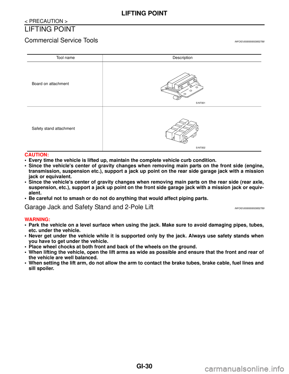
Tool name Description
Board on attachment
Safety stand attachment
S-NT001
S-NT002
Page 2526 of 5121
TOW TRUCK TOWING
GI-33
< PRECAUTION >
C
D
E
F
G
H
I
J
K
L
MB
GI
N
O
P
Do not use the vehicle tie downs to free a vehicle stuck in sand, snow, mud, etc. Never tow the vehi-
cle using the vehicle tie downs or recovery hooks.
Always pull the cable straight out from the front of the vehicle. Never pull on the hook at an angle.
Pulling devices should be routed so they do not touch any part of the suspension, steering, brake or
cooling systems.
Pulling devices such as ropes or canvas straps are not recommended for use in vehicle towing or
recovery.
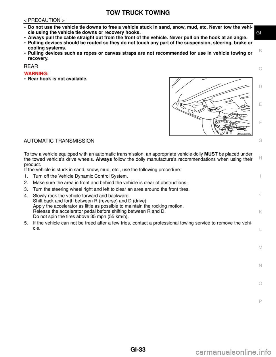
REAR
WARNING:
Rear hook is not available.
AUTOMATIC TRANSMISSION
To tow a vehicle equipped with an automatic transmission, an appropriate vehicle dolly MUST be placed under
the towed vehicle's drive wheels. Always follow the dolly manufacture's recommendations when using their
product.
If the vehicle is stuck in sand, snow, mud, etc., use the following procedure:
1. Turn off the Vehicle Dynamic Control System.
2. Make sure the area in front and behind the vehicle is clear of obstructions.
3. Turn the steering wheel right and left to clear an area around the front tires.
4. Slowly rock the vehicle forward and backward.
Shift back and forth between R (reverse) and D (drive).
Apply the accelerator as little as possible to maintain the rocking motion.
Release the accelerator pedal before shifting between R and D.
Do not spin the tires above 35 mph (55 km/h).
5. If the vehicle can not be freed after a few tries, contact a professional towing service to remove the vehi-
cle.
JMAIA0093ZZ
Page 3190 of 5121

MA-2
HEADLAMP AIMING ADJUSTMENT (HALOGEN
TYPE) : Aiming Adjustment Procedure (High
Beam) .....................................................................
30
EXHAUST SYSTEM ..................................................31
EXHAUST SYSTEM : Inspection ...........................32
CVT FLUID: RE0F10A ..............................................32
CVT FLUID: RE0F10A : Inspection ........................32
CVT FLUID: RE0F10A : Changing .........................33
CVT FLUID: RE0F09B ..............................................34
CVT FLUID: RE0F09B : Inspection ........................34
CVT FLUID: RE0F09B : Changing .........................35
WHEELS (BONDING WEIGHT TYPE) .....................35
WHEELS (BONDING WEIGHT TYPE) : Adjust-
ment ........................................................................
35
BRAKE FLUID LEVEL AND LEAKS ........................37
BRAKE FLUID LEVEL AND LEAKS : Inspection ...37
BRAKE LINES AND CABLES ..................................37
BRAKE LINES AND CABLES : Inspection .............38
BRAKE FLUID ..........................................................38
BRAKE FLUID : Changing ......................................38
DISC BRAKE ............................................................38
DISC BRAKE : Inspection ......................................38
DISC BRAKE : Front Disc Brake ............................39
DISC BRAKE : Rear Disc Brake .............................39
STEERING GEAR AND LINKAGE ...........................39
STEERING GEAR AND LINKAGE : Inspection ......39
POWER STEERING FLUID AND LINES ..................39
POWER STEERING FLUID AND LINES : Inspec-
tion ..........................................................................
40
AXLE AND SUSPENSION PARTS ...........................40
AXLE AND SUSPENSION PARTS : Inspection .....40
DRIVE SHAFT ...........................................................40
DRIVE SHAFT : Inspection .....................................41
BODY MAINTENANCE .....................................42
LOCKS, HINGES AND HOOD LATCH .....................42
LOCKS, HINGES AND HOOD LATCH : Lubricat-
ing ...........................................................................
42
SEAT BELT, BUCKLES, RETRACTORS, AN-
CHORS AND ADJUSTERS ......................................
42
SEAT BELT, BUCKLES, RETRACTORS, AN-
CHORS AND ADJUSTERS : Inspection .................
42
BODY CORROSION .................................................42
BODY CORROSION : Checking Body Corrosion ...42
SERVICE DATA AND SPECIFICATIONS
(SDS) ..........................................................
44
SERVICE DATA AND SPECIFICATIONS
(SDS) .................................................................
44
DRIVE BELTS ...........................................................44
DRIVE BELTS : Drive Belt ......................................44
ENGINE COOLANT ..................................................44
ENGINE COOLANT : Periodical Maintenance
Specification ............................................................
44
ENGINE OIL ..............................................................44
ENGINE OIL :
Periodical Maintenance Specification ....................
44
SPARK PLUG ...........................................................44
SPARK PLUG : Spark Plug ....................................44
ROAD WHEEL ..........................................................44
ROAD WHEEL : Road Wheel .................................44
Page 3196 of 5121
MA-8
< ON-VEHICLE MAINTENANCE >
PERIODIC MAINTENANCE
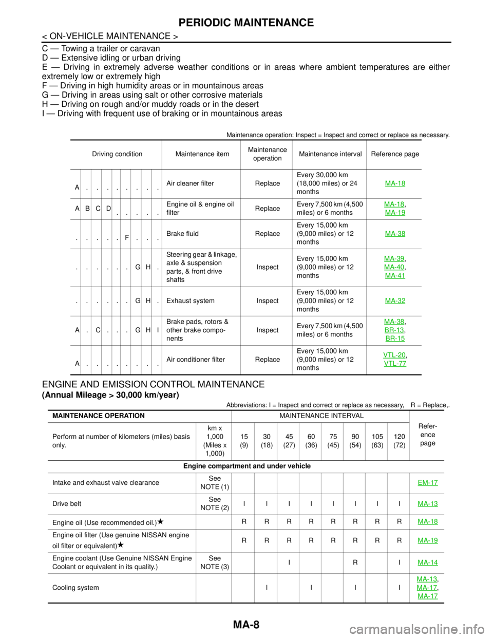
C — Towing a trailer or caravan
D — Extensive idling or urban driving
E — Driving in extremely adverse weather conditions or in areas where ambient temperatures are either
extremely low or extremely high
F — Driving in high humidity areas or in mountainous areas
G — Driving in areas using salt or other corrosive materials
H — Driving on rough and/or muddy roads or in the desert
I — Driving with frequent use of braking or in mountainous areas
Maintenance operation: Inspect = Inspect and correct or replace as necessary.
ENGINE AND EMISSION CONTROL MAINTENANCE
(Annual Mileage > 30,000 km/year)
Abbreviations: I = Inspect and correct or replace as necessary, R = Replace,.
Driving condition Maintenance itemMaintenance
operationMaintenance interval Reference page
A........Air cleaner filter ReplaceEvery 30,000 km
(18,000 miles) or 24
monthsMA-18
ABCD
.....Engine oil & engine oil
filter ReplaceEvery 7,500 km (4,500
miles) or 6 monthsMA-18,
MA-19
.....F...Brake fluid ReplaceEvery 15,000 km
(9,000 miles) or 12
monthsMA-38
......GH.Steering gear & linkage,
axle & suspension
parts, & front drive
shafts InspectEvery 15,000 km
(9,000 miles) or 12
monthsMA-39
,
MA-40
,
MA-41
. . . . . . G H . Exhaust system InspectEvery 15,000 km
(9,000 miles) or 12
monthsMA-32
A. C. . . GHIBrake pads, rotors &
other brake compo-
nentsInspectEvery 7,500 km (4,500
miles) or 6 monthsMA-38
,
BR-13
,
BR-15
A........Air conditioner filter ReplaceEvery 15,000 km
(9,000 miles) or 12
monthsVTL-20
,
VTL-77
MAINTENANCE OPERATIONMAINTENANCE INTERVAL
Refer-
ence
page Perform at number of kilometers (miles) basis
only.km x
1,000
(Miles x
1,000)15
(9)30
(18)45
(27)60
(36)75
(45)90
(54)105
(63)120
(72)
Engine compartment and under vehicle
Intake and exhaust valve clearanceSee
NOTE (1)EM-17
Drive beltSee
NOTE (2)I I IIIIIIMA-13
Engine oil (Use recommended oil.)R RRRRRRRMA-18
Engine oil filter (Use genuine NISSAN engine
oil filter or equivalent)R RRRRRRRMA-19
Engine coolant (Use Genuine NISSAN Engine
Coolant or equivalent in its quality.)See
NOTE (3)IRIMA-14
Cooling system I I I IMA-13
,
MA-17
,
MA-17
Page 3228 of 5121
MA-40
< ON-VEHICLE MAINTENANCE >
CHASSIS MAINTENANCE
POWER STEERING FLUID AND LINES : Inspection
INFOID:0000000003862441
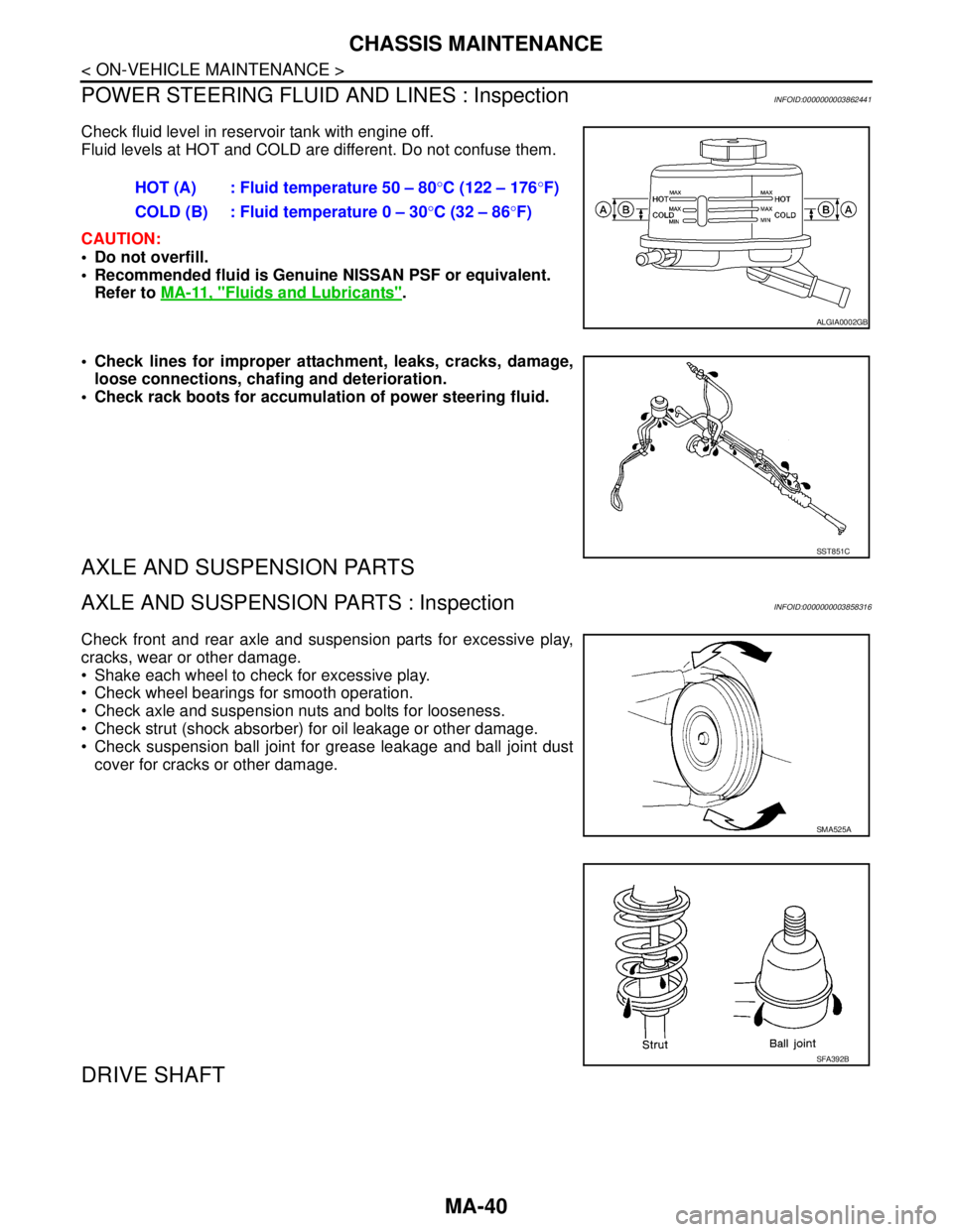
Check fluid level in reservoir tank with engine off.
Fluid levels at HOT and COLD are different. Do not confuse them.
CAUTION:
Do not overfill.
Recommended fluid is Genuine NISSAN PSF or equivalent.
Refer to MA-11, "
Fluids and Lubricants".
Check lines for improper attachment, leaks, cracks, damage,
loose connections, chafing and deterioration.
Check rack boots for accumulation of power steering fluid.
AXLE AND SUSPENSION PARTS
AXLE AND SUSPENSION PARTS : InspectionINFOID:0000000003858316
Check front and rear axle and suspension parts for excessive play,
cracks, wear or other damage.
Shake each wheel to check for excessive play.
Check wheel bearings for smooth operation.
Check axle and suspension nuts and bolts for looseness.
Check strut (shock absorber) for oil leakage or other damage.
Check suspension ball joint for grease leakage and ball joint dust
cover for cracks or other damage.
DRIVE SHAFT
HOT (A) : Fluid temperature 50 – 80°C (122 – 176°F)
COLD (B) : Fluid temperature 0 – 30°C (32 – 86°F)
ALGIA0002GB
SST851C
SMA525A
SFA392B
Page 3727 of 5121

RAX-2
< SYMPTOM DIAGNOSIS >
NOISE, VIBRATION AND HARSHNESS (NVH) TROUBLESHOOTING
SYMPTOM DIAGNOSIS
NOISE, VIBRATION AND HARSHNESS (NVH) TROUBLESHOOTING
NVH Troubleshooting ChartINFOID:0000000003811096
Use chart below to find the cause of the symptom. If necessary, repair or replace these parts.
×: ApplicableReference page
RAX-4—
RAX-3
NVH in RAX and RSU sections
NVH in WT section
NVH in WT section
NVH in BR section
Possible cause and SUSPECTED PARTS
Improper installation, looseness
Parts interference
Wheel bearing damage
REAR AXLE AND REAR SUSPENSION
TIRE
ROAD WHEEL
BRAKE
Symptom REAR AXLENoise×××××××
Shake×××××××
Vibration×××××
Shimmy×× ××××
Judder×××××
Poor quality ride or handling×× ×××
Page 3729 of 5121
RAX-4
< ON-VEHICLE REPAIR >
REAR WHEEL HUB AND HOUSING
ON-VEHICLE REPAIR
REAR WHEEL HUB AND HOUSING
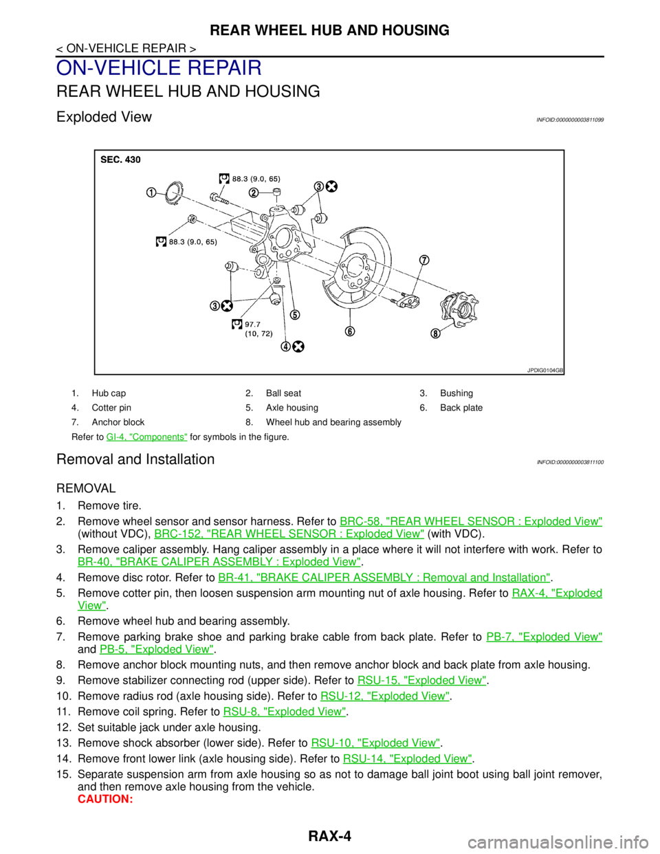
Exploded ViewINFOID:0000000003811099
Removal and InstallationINFOID:0000000003811100
REMOVAL
1. Remove tire.
2. Remove wheel sensor and sensor harness. Refer to BRC-58, "
REAR WHEEL SENSOR : Exploded View"
(without VDC), BRC-152, "REAR WHEEL SENSOR : Exploded View" (with VDC).
3. Remove caliper assembly. Hang caliper assembly in a place where it will not interfere with work. Refer to
BR-40, "
BRAKE CALIPER ASSEMBLY : Exploded View".
4. Remove disc rotor. Refer to BR-41, "
BRAKE CALIPER ASSEMBLY : Removal and Installation".
5. Remove cotter pin, then loosen suspension arm mounting nut of axle housing. Refer to RAX-4, "
Exploded
View".
6. Remove wheel hub and bearing assembly.
7. Remove parking brake shoe and parking brake cable from back plate. Refer to PB-7, "
Exploded View"
and PB-5, "Exploded View".
8. Remove anchor block mounting nuts, and then remove anchor block and back plate from axle housing.
9. Remove stabilizer connecting rod (upper side). Refer to RSU-15, "
Exploded View".
10. Remove radius rod (axle housing side). Refer to RSU-12, "
Exploded View".
11. Remove coil spring. Refer to RSU-8, "
Exploded View".
12. Set suitable jack under axle housing.
13. Remove shock absorber (lower side). Refer to RSU-10, "
Exploded View".
14. Remove front lower link (axle housing side). Refer to RSU-14, "
Exploded View".
15. Separate suspension arm from axle housing so as not to damage ball joint boot using ball joint remover,
and then remove axle housing from the vehicle.
CAUTION:
1. Hub cap 2. Ball seat 3. Bushing
4. Cotter pin 5. Axle housing 6. Back plate
7. Anchor block 8. Wheel hub and bearing assembly
Refer to GI-4, "
Components" for symbols in the figure.
JPDIG0104GB