Page 4392 of 5121

ST-2
< SYMPTOM DIAGNOSIS >
NOISE, VIBRATION AND HARSHNESS (NVH) TROUBLESHOOTING
SYMPTOM DIAGNOSIS
NOISE, VIBRATION AND HARSHNESS (NVH) TROUBLESHOOTING
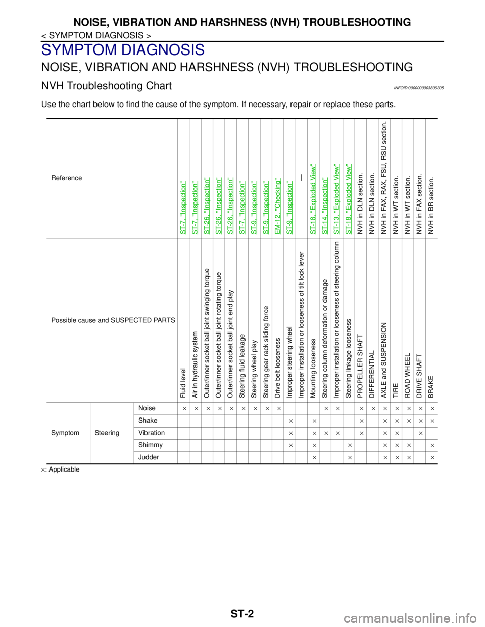
NVH Troubleshooting ChartINFOID:0000000003806305
Use the chart below to find the cause of the symptom. If necessary, repair or replace these parts.
×: ApplicableReference
ST-7, "
Inspection
"
ST-7, "
Inspection
"
ST-26, "
Inspection
"
ST-26, "
Inspection
"
ST-26, "
Inspection
"
ST-7, "
Inspection
"
ST-9, "
Inspection
"
ST-9, "
Inspection
"
EM-12, "
Checking
"
ST-9, "
Inspection
"—
ST-18, "
Exploded View
"
ST-14, "
Inspection
"
ST-13, "
Exploded View
"
ST-18, "
Exploded View
"
NVH in DLN section.
NVH in DLN section.
NVH in FAX, RAX, FSU, RSU section.
NVH in WT section.
NVH in WT section.
NVH in FAX section.
NVH in BR section.
Possible cause and SUSPECTED PARTS
Fluid level
Air in hydraulic system
Outer/inner socket ball joint swinging torque
Outer/inner socket ball joint rotating torque
Outer/inner socket ball joint end play
Steering fluid leakage
Steering wheel play
Steering gear rack sliding force
Drive belt looseness
Improper steering wheel
Improper installation or looseness of tilt lock lever
Mounting looseness
Steering column deformation or damage
Improper installation or looseness of steering column
Steering linkage looseness
PROPELLER SHAFT
DIFFERENTIAL
AXLE and SUSPENSION
TIRE
ROAD WHEEL
DRIVE SHAFT
BRAKE
Symptom SteeringNoise××××××××× ×× ×××××××
Shake× × × ×××××
Vibration××××××××
Shimmy×× × ××××
Judder××××××
Page 4399 of 5121

STEERING WHEEL
ST-9
< ON-VEHICLE MAINTENANCE >
C
D
E
F
H
I
J
K
L
MA
B
ST
N
O
P
STEERING WHEEL
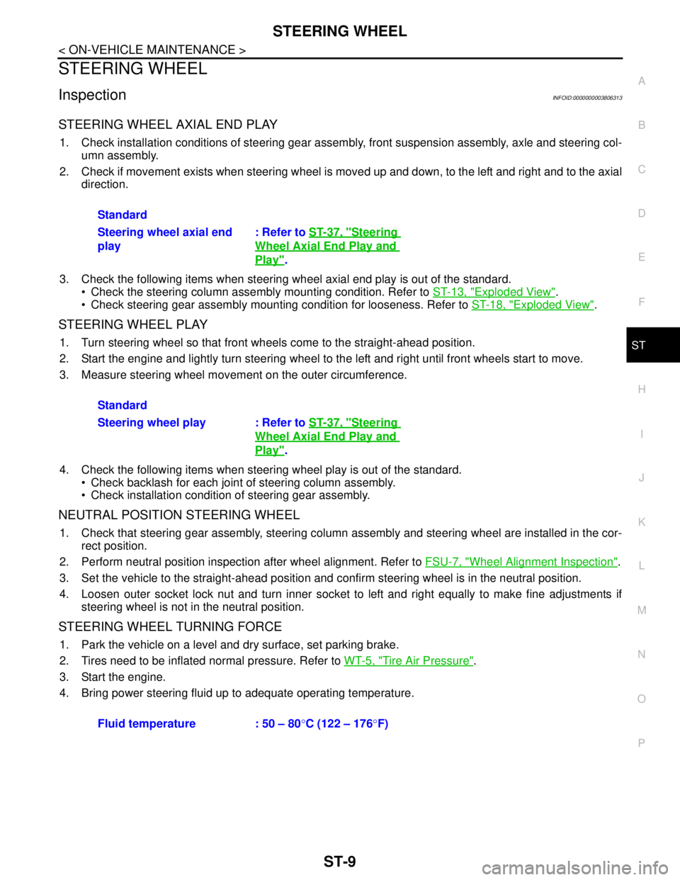
InspectionINFOID:0000000003806313
STEERING WHEEL AXIAL END PLAY
1. Check installation conditions of steering gear assembly, front suspension assembly, axle and steering col-
umn assembly.
2. Check if movement exists when steering wheel is moved up and down, to the left and right and to the axial
direction.
3. Check the following items when steering wheel axial end play is out of the standard.
Check the steering column assembly mounting condition. Refer to ST-13, "
Exploded View".
Check steering gear assembly mounting condition for looseness. Refer to ST-18, "
Exploded View".
STEERING WHEEL PLAY
1. Turn steering wheel so that front wheels come to the straight-ahead position.
2. Start the engine and lightly turn steering wheel to the left and right until front wheels start to move.
3. Measure steering wheel movement on the outer circumference.
4. Check the following items when steering wheel play is out of the standard.
Check backlash for each joint of steering column assembly.
Check installation condition of steering gear assembly.
NEUTRAL POSITION STEERING WHEEL
1. Check that steering gear assembly, steering column assembly and steering wheel are installed in the cor-
rect position.
2. Perform neutral position inspection after wheel alignment. Refer to FSU-7, "
Wheel Alignment Inspection".
3. Set the vehicle to the straight-ahead position and confirm steering wheel is in the neutral position.
4. Loosen outer socket lock nut and turn inner socket to left and right equally to make fine adjustments if
steering wheel is not in the neutral position.
STEERING WHEEL TURNING FORCE
1. Park the vehicle on a level and dry surface, set parking brake.
2. Tires need to be inflated normal pressure. Refer to WT-5, "
Tire Air Pressure".
3. Start the engine.
4. Bring power steering fluid up to adequate operating temperature.Standard
Steering wheel axial end
play: Refer to ST-37, "
Steering
Wheel Axial End Play and
Play".
Standard
Steering wheel play : Refer to ST-37, "
Steering
Wheel Axial End Play and
Play".
Fluid temperature : 50 – 80°C (122 – 176°F)
Page 4401 of 5121
STEERING WHEEL
ST-11
< ON-VEHICLE MAINTENANCE >
C
D
E
F
H
I
J
K
L
MA
B
ST
N
O
P
5. Check the following items when turning angle is out of the stan-
dard.
a. Check the neutral position of the rack stroke (L).
b. Disassemble steering gear assembly to check the cause that
rack stroke is outside of the standard.
Steering angles are not adjustable. Check steering gear
assembly, steering column assembly and front suspension
components for wear or damage if any of the turning angles are different from the specified value.
Replace any of them, if any non-standard condition exists. Standard
L : Refer to ST-38, "
Rack
Stroke".
SGIA0629J
Page 4641 of 5121
TM-168
< REMOVAL AND INSTALLATION >[CVT: RE0F09B]
TRANSAXLE ASSEMBLY
REMOVAL AND INSTALLATION
TRANSAXLE ASSEMBLY
Exploded ViewINFOID:0000000003849108
Removal and InstallationINFOID:0000000003849109
WARNING:
Never remove the reservoir tank cap when the engine is hot. Serious burns could occur from high
pressure engine coolant escaping from the reservoir tank.
REMOVAL
1. Remove the engine, the transaxle assembly and front suspension member. Refer to EM-67, "Exploded
View".
2. Lift with hoist and separate engine, transaxle assembly from front suspension member. Refer to EM-67,
"Exploded View".
1. CVT fluid level gauge 2. CVT fluid charging pipe 3. O-ring
4. Transaxle assembly
A. For tightening torque, refer to TM-168, "
Removal and Installation".
Refer to GI-4, "
Components" for symbols in the figure.
JPDIA0799GB
Page 4805 of 5121
![NISSAN TEANA 2008 Service Manual TM-332
< REMOVAL AND INSTALLATION >[CVT: RE0F10A]
TRANSAXLE ASSEMBLY
REMOVAL AND INSTALLATION
TRANSAXLE ASSEMBLY
Exploded ViewINFOID:0000000003806551
Removal and InstallationINFOID:0000000003806552
WA NISSAN TEANA 2008 Service Manual TM-332
< REMOVAL AND INSTALLATION >[CVT: RE0F10A]
TRANSAXLE ASSEMBLY
REMOVAL AND INSTALLATION
TRANSAXLE ASSEMBLY
Exploded ViewINFOID:0000000003806551
Removal and InstallationINFOID:0000000003806552
WA](/manual-img/5/57391/w960_57391-4804.png)
TM-332
< REMOVAL AND INSTALLATION >[CVT: RE0F10A]
TRANSAXLE ASSEMBLY
REMOVAL AND INSTALLATION
TRANSAXLE ASSEMBLY
Exploded ViewINFOID:0000000003806551
Removal and InstallationINFOID:0000000003806552
WARNING:
Never remove the reservoir tank cap when the engine is hot. Serious burns could occur from high
pressure engine coolant escaping from the reservoir tank.
REMOVAL
1. Remove the engine, the transaxle assembly and front suspension member. Refer to EM-67, "Exploded
View".
2. Lift with hoist and separate engine, transaxle assembly from front suspension member. Refer to EM-67,
"Exploded View".
3. Remove air breather hose. Refer to TM-328, "
Exploded View".
4. Remove CVT fluid level gauge and CVT fluid charging pipe.
5. Disconnect the following connectors:
Primary speed sensor connector
Secondary speed sensor connector
PNP switch connector
CVT unit connector
6. Remove crankshaft position sensor (POS). Refer to EM-38, "
Exploded View".
1. Transaxle assembly 2. O-ring 3. CVT fluid charging pipe
4. CVT fluid level gauge
A. For tightening torque, refer to TM-332, "
Removal and Installation".
B. To water outlet
Refer to GI-4, "
Components" for symbols in the figure.
JPDIA0736GB
Page 5008 of 5121
WT-1
SUSPENSION
C
DF
G H
I
J
K L
M
SECTION WT
A
B
WT
N
O PCONTENTS
ROAD WHEELS & TIRES
ON-VEHICLE MAINTENA NCE .....................2
ROAD WHEEL ............................................... .....2
Inspection ............................................................ ......2
ON-VEHICLE REPAIR ..................................3
ROAD WHEEL TIRE ASSEMBLY ................. .....3
Adjustment .......................................................... ......3
SERVICE DATA AND SPECIFICATIONS
(SDS) ............... ..............................................
5
SERVICE DATA AND SPECIFICATIONS
(SDS) ..................................................................
5
Road Wheel ......................................................... .....5
Wheel Nut .................................................................5
Tire Air Pressure .......................................................5