2008 NISSAN TEANA wheel
[x] Cancel search: wheelPage 1127 of 5121

CO-4
< SYMPTOM DIAGNOSIS >
OVERHEATING CAUSE ANALYSIS
Except cool-
ing system
parts mal-
function— Overload on engineAbusive drivingHigh engine rpm under no
load
Driving in low gear for ex-
tended time
Driving at extremely high
speed
Powertrain system malfunc-
tion
— Installed improper size
wheels and tires
Dragging brakes
Improper ignition timing
Blocked or restricted air
flowBlocked bumper —
— Blocked radiator grilleInstalled car brassiere
Mud contamination or paper
clogging
Blocked radiator —
Blocked condenser
Blocked air flow
Installed large fog lamp Symptom Check items
Page 1141 of 5121

CO-18
< ON-VEHICLE REPAIR >
WATER PUMP
WATER PUMP
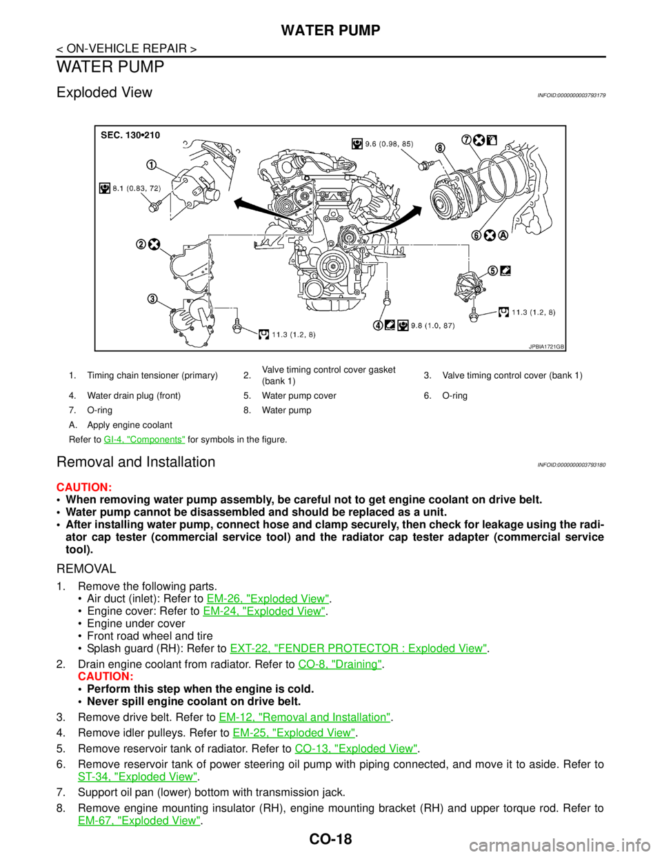
Exploded ViewINFOID:0000000003793179
Removal and InstallationINFOID:0000000003793180
CAUTION:
When removing water pump assembly, be careful not to get engine coolant on drive belt.
Water pump cannot be disassembled and should be replaced as a unit.
After installing water pump, connect hose and clamp securely, then check for leakage using the radi-
ator cap tester (commercial service tool) and the radiator cap tester adapter (commercial service
tool).
REMOVAL
1. Remove the following parts.
Air duct (inlet): Refer to EM-26, "
Exploded View".
Engine cover: Refer to EM-24, "
Exploded View".
Engine under cover
Front road wheel and tire
Splash guard (RH): Refer to EXT-22, "
FENDER PROTECTOR : Exploded View".
2. Drain engine coolant from radiator. Refer to CO-8, "
Draining".
CAUTION:
Perform this step when the engine is cold.
Never spill engine coolant on drive belt.
3. Remove drive belt. Refer to EM-12, "
Removal and Installation".
4. Remove idler pulleys. Refer to EM-25, "
Exploded View".
5. Remove reservoir tank of radiator. Refer to CO-13, "
Exploded View".
6. Remove reservoir tank of power steering oil pump with piping connected, and move it to aside. Refer to
ST-34, "
Exploded View".
7. Support oil pan (lower) bottom with transmission jack.
8. Remove engine mounting insulator (RH), engine mounting bracket (RH) and upper torque rod. Refer to
EM-67, "
Exploded View".
1. Timing chain tensioner (primary) 2.Valve timing control cover gasket
(bank 1)3. Valve timing control cover (bank 1)
4. Water drain plug (front) 5. Water pump cover 6. O-ring
7. O-ring 8. Water pump
A. Apply engine coolant
Refer to GI-4, "
Components" for symbols in the figure.
JPBIA1721GB
Page 1191 of 5121

BCM (BODY CONTROL MODULE)
DEF-41
< ECU DIAGNOSIS >
C
D
E
F
G
H
I
J
K
MA
B
DEF
N
O
P
93
(Y)Ground ON indicator lamp Output Ignition switchOFF (LOCK indicator is
not illuminated)Battery voltage
ON or ACC 0 V
95
(L)Ground ACC relay control Output Ignition switchOFF 0 V
ACC or ON Battery voltage
96
(Y/R)GroundControl device (de-
tention switch) pow-
er supplyOutput — Battery voltage
97
(L/O)GroundSteering lock condi-
tion No. 1Input Steering lockLOCK status 0 V
UNLOCK status Battery voltage
98
(G/R)GroundSteering lock condi-
tion No. 2Input Steering lockLOCK status Battery voltage
UNLOCK status 0 V
99
(G/B)GroundSelector lever P po-
sition switchInput Selector leverP position 0 V
Any position other than P Battery voltage
100
(P/L)GroundPassenger door re-
quest switchInputPassenger door
request switchON (Pressed) 0 V
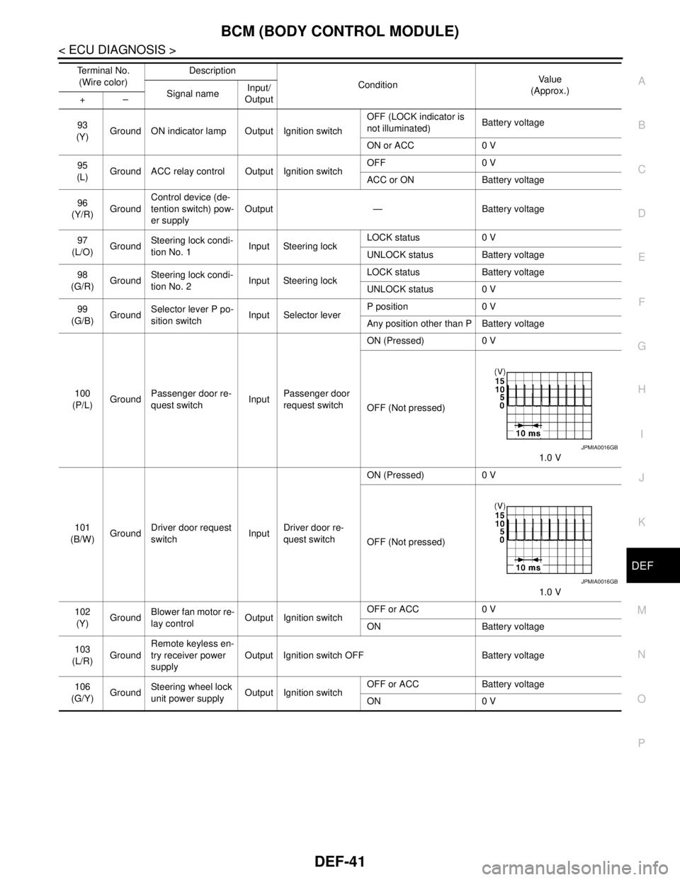
OFF (Not pressed)
1.0 V
101
(B/W)GroundDriver door request
switchInputDriver door re-
quest switchON (Pressed) 0 V
OFF (Not pressed)
1.0 V
102
(Y)GroundBlower fan motor re-
lay controlOutput Ignition switchOFF or ACC 0 V
ON Battery voltage
103
(L/R)GroundRemote keyless en-
try receiver power
supplyOutput Ignition switch OFF Battery voltage
106
(G/Y)GroundSteering wheel lock
unit power supplyOutput Ignition switchOFF or ACC Battery voltage
ON 0 V Te r m i n a l N o .
(Wire color)Description
ConditionVa l u e
(Approx.)
Signal nameInput/
Output +–
JPMIA0016GB
JPMIA0016GB
Page 1216 of 5121

DEF-66
< ON-VEHICLE REPAIR >
CONDENSER
CONDENSER
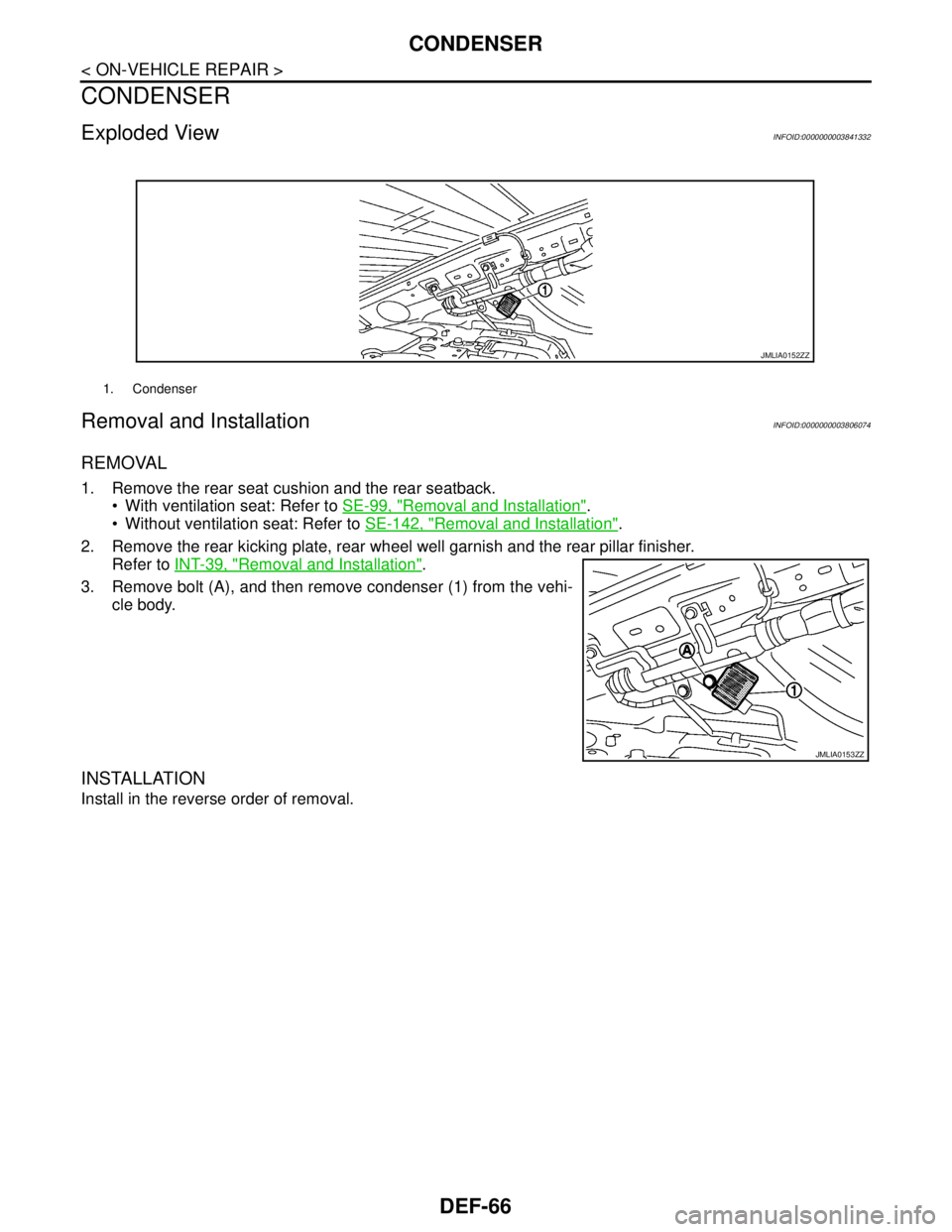
Exploded ViewINFOID:0000000003841332
Removal and InstallationINFOID:0000000003806074
REMOVAL
1. Remove the rear seat cushion and the rear seatback.
With ventilation seat: Refer to SE-99, "
Removal and Installation".
Without ventilation seat: Refer to SE-142, "
Removal and Installation".
2. Remove the rear kicking plate, rear wheel well garnish and the rear pillar finisher.
Refer to INT-39, "
Removal and Installation".
3. Remove bolt (A), and then remove condenser (1) from the vehi-
cle body.
INSTALLATION
Install in the reverse order of removal.
1. Condenser
JMLIA0152ZZ
JMLIA0153ZZ
Page 1220 of 5121

DLK-4
PASSENGER SIDE : Diagnosis Procedure ..........162
TRUNK .....................................................................162
TRUNK : Description .............................................162
TRUNK : Diagnosis Procedure ..............................163
TRUNK LID DOES NOT OPEN WITH TRUNK
LID OPENER SWITCH ....................................
164
Description .............................................................164
Diagnosis Procedure .............................................164
TRUNK LID DOES NOT OPEN WITH INTEL-
LIGENT KEY ....................................................
165
Description .............................................................165
Diagnosis Procedure .............................................165
TRUNK LID DOES NOT OPEN WITH TRUNK
LID OPENER REQUEST SWITCH ..................
166
Description .............................................................166
Diagnosis Procedure .............................................166
HAZARD AND BUZZER REMINDER DOES
NOT OPERATE ...............................................
167
Description .............................................................167
Diagnosis Procedure .............................................167
KEY REMINDER FUNCTION DOES NOT OP-
ERATE .............................................................
168
Description .............................................................168
Diagnosis Procedure .............................................168
KEY WARNING DOES NOT OPERATE .........169
Description .............................................................169
Diagnosis Procedure .............................................169
OFF POSITION WARNING DOES NOT OP-
ERATE .............................................................
170
Description .............................................................170
Diagnosis Procedure .............................................170
P POSITION WARNING DOES NOT OPER-
ATE ..................................................................
171
Description .............................................................171
Diagnosis Procedure .............................................171
ACC WARNING DOES NOT OPERATE .........173
Description .............................................................173
Diagnosis Procedure .............................................173
TAKE AWAY WARNING DOES NOT OPER-
ATE ..................................................................
174
DOOR IS OPEN .......................................................174
DOOR IS OPEN : Description ...............................174
DOOR IS OPEN : Diagnosis Procedure ................174
ANY DOOR OPEN TO ALL DOORS CLOSED .......175
ANY DOOR OPEN TO ALL DOORS CLOSED :
Description .............................................................
175
ANY DOOR OPEN TO ALL DOORS CLOSED :
Diagnosis Procedure .............................................
175
PUSH-BUTTON IGNITION SWITCH OPERATION .175
PUSH-BUTTON IGNITION SWITCH OPERA-
TION : Description ................................................
176
PUSH-BUTTON IGNITION SWITCH OPERA-
TION : Diagnosis Procedure .................................
176
INTELLIGENT KEY IS REMOVED FROM KEY
SLOT .......................................................................
176
INTELLIGENT KEY IS REMOVED FROM KEY
SLOT : Description ................................................
176
INTELLIGENT KEY IS REMOVED FROM KEY
SLOT : Diagnosis Procedure ................................
177
INTELLIGENT KEY LOW BATTERY WARN-
ING DOES NOT OPERATE ..............................
178
Description ............................................................178
Diagnosis Procedure .............................................178
DOOR LOCK OPERATION WARNING DOES
NOT OPERATE WITH DOOR REQUEST
SWITCH ............................................................
179
Description ............................................................179
Diagnosis Procedure .............................................179
KEY ID WARNING DOES NOT OPERATE .....180
Description ............................................................180
Diagnosis Procedure .............................................180
INTELLIGENT KEY LOW BATTERY WARN-
ING DOES NOT OPERATE ..............................
181
Description ............................................................181
Diagnosis Procedure .............................................181
SQUEAK AND RATTLE TROUBLE DIAG-
NOSES ..............................................................
182
Work Flow .............................................................182
Inspection Procedure ............................................184
Diagnostic Worksheet ...........................................186
PRECAUTION ...........................................188
PRECAUTIONS ................................................188
Precaution for Supplemental Restraint System
(SRS) "AIR BAG" and "SEAT BELT PRE-TEN-
SIONER" ...............................................................
188
Precaution for Procedure without Cowl Top Cover .188
Precaution Necessary for Steering Wheel Rota-
tion after Battery Disconnect .................................
188
Work ......................................................................189
PREPARATION .........................................190
PREPARATION ................................................190
Commercial Service Tools ....................................190
ON-VEHICLE REPAIR ..............................191
HOOD ...............................................................191
HOOD ASSEMBLY .................................................191
HOOD ASSEMBLY : Exploded View ....................191
Page 1352 of 5121
![NISSAN TEANA 2008 Service Manual DLK-136
< ECU DIAGNOSIS >[WITH INTELLIGENT KEY SYSTEM]
BCM (BODY CONTROL MODULE)
93
(Y)Ground ON indicator lamp Output Ignition switchOFF (LOCK indicator is
not illuminated)Battery voltage
ON or ACC NISSAN TEANA 2008 Service Manual DLK-136
< ECU DIAGNOSIS >[WITH INTELLIGENT KEY SYSTEM]
BCM (BODY CONTROL MODULE)
93
(Y)Ground ON indicator lamp Output Ignition switchOFF (LOCK indicator is
not illuminated)Battery voltage
ON or ACC](/manual-img/5/57391/w960_57391-1351.png)
DLK-136
< ECU DIAGNOSIS >[WITH INTELLIGENT KEY SYSTEM]
BCM (BODY CONTROL MODULE)
93
(Y)Ground ON indicator lamp Output Ignition switchOFF (LOCK indicator is
not illuminated)Battery voltage
ON or ACC 0 V
95
(L)Ground ACC relay control Output Ignition switchOFF 0 V
ACC or ON Battery voltage
96
(Y/R)GroundControl device (de-
tention switch) pow-
er supplyOutput — Battery voltage
97
(L/O)GroundSteering lock condi-
tion No. 1Input Steering lockLOCK status 0 V
UNLOCK status Battery voltage
98
(G/R)GroundSteering lock condi-
tion No. 2Input Steering lockLOCK status Battery voltage
UNLOCK status 0 V
99
(G/B)GroundSelector lever P po-
sition switchInput Selector leverP position 0 V
Any position other than P Battery voltage
100
(P/L)GroundPassenger door re-
quest switchInputPassenger door
request switchON (Pressed) 0 V
OFF (Not pressed)
1.0 V
101
(B/W)GroundDriver door request
switchInputDriver door re-
quest switchON (Pressed) 0 V
OFF (Not pressed)
1.0 V
102
(Y)GroundBlower fan motor re-
lay controlOutput Ignition switchOFF or ACC 0 V
ON Battery voltage
103
(L/R)GroundRemote keyless en-
try receiver power
supplyOutput Ignition switch OFF Battery voltage
106
(G/Y)GroundSteering wheel lock
unit power supplyOutput Ignition switchOFF or ACC Battery voltage
ON 0 V Te r m i n a l N o .
(Wire color)Description
ConditionVa l u e
(Approx.)
Signal nameInput/
Output +–
JPMIA0016GB
JPMIA0016GB
Page 1404 of 5121
![NISSAN TEANA 2008 Service Manual DLK-188
< PRECAUTION >[WITH INTELLIGENT KEY SYSTEM]
PRECAUTIONS
PRECAUTION
PRECAUTIONS
Precaution for Supplemental Restraint System (SRS) "AIR BAG" and "SEAT BELT
PRE-TENSIONER"
INFOID:00000000039419 NISSAN TEANA 2008 Service Manual DLK-188
< PRECAUTION >[WITH INTELLIGENT KEY SYSTEM]
PRECAUTIONS
PRECAUTION
PRECAUTIONS
Precaution for Supplemental Restraint System (SRS) "AIR BAG" and "SEAT BELT
PRE-TENSIONER"
INFOID:00000000039419](/manual-img/5/57391/w960_57391-1403.png)
DLK-188
< PRECAUTION >[WITH INTELLIGENT KEY SYSTEM]
PRECAUTIONS
PRECAUTION
PRECAUTIONS
Precaution for Supplemental Restraint System (SRS) "AIR BAG" and "SEAT BELT
PRE-TENSIONER"
INFOID:0000000003941991
The Supplemental Restraint System such as “AIR BAG” and “SEAT BELT PRE-TENSIONER”, used along
with a front seat belt, helps to reduce the risk or severity of injury to the driver and front passenger for certain
types of collision. Information necessary to service the system safely is included in the “SRS AIRBAG” and
“SEAT BELT” of this Service Manual.
WARNING:
To avoid rendering the SRS inoperative, which could increase the risk of personal injury or death in
the event of a collision which would result in air bag inflation, all maintenance must be performed by
an authorized NISSAN/INFINITI dealer.
Improper maintenance, including incorrect removal and installation of the SRS, can lead to personal
injury caused by unintentional activation of the system. For removal of Spiral Cable and Air Bag
Module, see the “SRS AIRBAG”.
Never use electrical test equipment on any circuit related to the SRS unless instructed to in this Ser-
vice Manual. SRS wiring harnesses can be identified by yellow and/or orange harnesses or harness
connectors.
Precaution for Procedure without Cowl Top CoverINFOID:0000000003795058
When performing the procedure after removing cowl top cover, cover
the lower end of windshield with urethane, etc.
Precaution Necessary for Steering Wheel Rotation after Battery Disconnect
INFOID:0000000003845516
NOTE:
Before removing and installing any control units, first turn the push-button ignition switch to the LOCK posi-
tion, then disconnect both battery cables.
After finishing work, confirm that all control unit connectors are connected properly, then re-connect both
battery cables.
Always use CONSULT-III to perform self-diagnosis as a part of each function inspection after finishing work.
If a DTC is detected, perform trouble diagnosis according to self-diagnosis results.
This vehicle is equipped with a push-button ignition switch and a steering lock unit.
If the battery is disconnected or discharged, the steering wheel will lock and cannot be turned.
If turning the steering wheel is required with the battery disconnected or discharged, follow the procedure
below before starting the repair operation.
OPERATION PROCEDURE
1. Connect both battery cables.
NOTE:
Supply power using jumper cables if battery is discharged.
2. Turn the push-button ignition switch to ACC position.
(At this time, the steering lock will be released.)
3. Disconnect both battery cables. The steering lock will remain released with both battery cables discon-
nected and the steering wheel can be turned.
4. Perform the necessary repair operation.
PIIB3706J
Page 1405 of 5121
![NISSAN TEANA 2008 Service Manual PRECAUTIONS
DLK-189
< PRECAUTION >[WITH INTELLIGENT KEY SYSTEM]
C
D
E
F
G
H
I
J
L
MA
B
DLK
N
O
P
5. When the repair work is completed, re-connect both battery cables. With the brake pedal released, tu NISSAN TEANA 2008 Service Manual PRECAUTIONS
DLK-189
< PRECAUTION >[WITH INTELLIGENT KEY SYSTEM]
C
D
E
F
G
H
I
J
L
MA
B
DLK
N
O
P
5. When the repair work is completed, re-connect both battery cables. With the brake pedal released, tu](/manual-img/5/57391/w960_57391-1404.png)
PRECAUTIONS
DLK-189
< PRECAUTION >[WITH INTELLIGENT KEY SYSTEM]
C
D
E
F
G
H
I
J
L
MA
B
DLK
N
O
P
5. When the repair work is completed, re-connect both battery cables. With the brake pedal released, turn
the push-button ignition switch from ACC position to ON position, then to LOCK position. (The steering
wheel will lock when the push-button ignition switch is turned to LOCK position.)
6. Perform self-diagnosis check of all control units using CONSULT-III.
WorkINFOID:0000000003795060
After removing and installing the opening/closing parts, be sure to carry out fitting adjustments to check their
operational.
Check the lubrication level, damage, and wear of each part. If necessary, grease or replace it.