2008 NISSAN TEANA wheel
[x] Cancel search: wheelPage 1876 of 5121
EM-1
ENGINE
C
D
E
F
G
H
I
J
K
L
M
SECTION EM
A
EM
N
O
P
CONTENTS
ENGINE MECHANICAL
SYMPTOM DIAGNOSIS ...............................3
NOISE, VIBRATION AND HARSHNESS
(NVH) TROUBLESHOOTING .............................
3
NVH Troubleshooting - Engine Noise .......................3
Use the Chart Below to Help You Find the Cause
of the Symptom .........................................................
4
PRECAUTION ...............................................5
PRECAUTIONS ...................................................5
Precaution for Procedure without Cowl Top Cover ......5
Precaution for Supplemental Restraint System
(SRS) "AIR BAG" and "SEAT BELT PRE-TEN-
SIONER" ...................................................................
5
Precaution Necessary for Steering Wheel Rota-
tion after Battery Disconnect .....................................
5
Precaution for Drain Engine Coolant and Engine
Oil ..............................................................................
6
Precaution for Disconnecting Fuel Piping .................6
Precaution for Removal and Disassembly ................6
Precaution for Inspection, Repair and Replace-
ment ..........................................................................
6
Precaution for Assembly and Installation ..................6
Precaution for Angle Tightening ................................6
Precaution for Liquid Gasket .....................................7
PREPARATION ............................................8
PREPARATION ...................................................8
Special Service Tool .................................................8
Commercial Service Tool ..........................................9
ON-VEHICLE MAINTENANCE ....................12
DRIVE BELT .......................................................12
Exploded View ........................................................12
Checking .................................................................12
Tension Adjustment ................................................12
Removal and Installation .........................................12
AIR CLEANER FILTER ......................................14
Removal and Installation .........................................14
SPARK PLUG ...................................................15
Exploded View .........................................................15
Removal and Installation .........................................15
Inspection ................................................................16
CAMSHAFT VALVE CLEARANCE ..................17
Inspection and Adjustment ......................................17
COMPRESSION PRESSURE ...........................22
Inspection ................................................................22
ON-VEHICLE REPAIR .................................24
ENGINE COVER ...............................................24
Exploded View .........................................................24
Removal and Installation .........................................24
DRIVE BELT AUTO TENSIONER AND IDLER
PULLEY .............................................................
25
Exploded View .........................................................25
Removal and Installation .........................................25
AIR CLEANER AND AIR DUCT .......................26
Exploded View .........................................................26
Removal and Installation .........................................26
Inspection ................................................................27
INTAKE MANIFOLD COLLECTOR ..................28
Exploded View .........................................................28
Removal and Installation .........................................29
INTAKE MANIFOLD .........................................32
Exploded View .........................................................32
Removal and Installation .........................................32
Inspection ................................................................33
EXHAUST MANIFOLD AND THREE WAY
CATALYST ........................................................
34
Exploded View .........................................................34
Removal and Installation .........................................34
Inspection ................................................................37
Page 1880 of 5121
PRECAUTIONS
EM-5
< PRECAUTION >
C
D
E
F
G
H
I
J
K
L
MA
EM
N
P O
PRECAUTION
PRECAUTIONS
Precaution for Procedure without Cowl Top CoverINFOID:0000000003802312
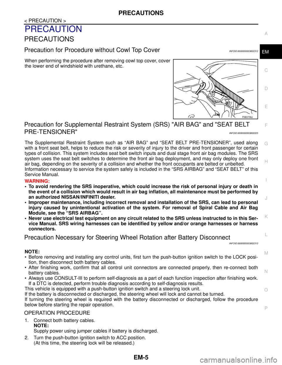
When performing the procedure after removing cowl top cover, cover
the lower end of windshield with urethane, etc.
Precaution for Supplemental Restraint System (SRS) "AIR BAG" and "SEAT BELT
PRE-TENSIONER"
INFOID:0000000003802225
The Supplemental Restraint System such as “AIR BAG” and “SEAT BELT PRE-TENSIONER”, used along
with a front seat belt, helps to reduce the risk or severity of injury to the driver and front passenger for certain
types of collision. This system includes seat belt switch inputs and dual stage front air bag modules. The SRS
system uses the seat belt switches to determine the front air bag deployment, and may only deploy one front
air bag, depending on the severity of a collision and whether the front occupants are belted or unbelted.
Information necessary to service the system safely is included in the “SRS AIRBAG” and “SEAT BELT” of this
Service Manual.
WARNING:
• To avoid rendering the SRS inoperative, which could increase the risk of personal injury or death in
the event of a collision which would result in air bag inflation, all maintenance must be performed by
an authorized NISSAN/INFINITI dealer.
Improper maintenance, including incorrect removal and installation of the SRS, can lead to personal
injury caused by unintentional activation of the system. For removal of Spiral Cable and Air Bag
Module, see the “SRS AIRBAG”.
Never use electrical test equipment on any circuit related to the SRS unless instructed to in this Ser-
vice Manual. SRS wiring harnesses can be identified by yellow and/or orange harnesses or harness
connectors.
Precaution Necessary for Steering Wheel Rotation after Battery Disconnect
INFOID:0000000003802313
NOTE:
Before removing and installing any control units, first turn the push-button ignition switch to the LOCK posi-
tion, then disconnect both battery cables.
After finishing work, confirm that all control unit connectors are connected properly, then re-connect both
battery cables.
Always use CONSULT-III to perform self-diagnosis as a part of each function inspection after finishing work.
If a DTC is detected, perform trouble diagnosis according to self-diagnosis results.
This vehicle is equipped with a push-button ignition switch and a steering lock unit.
If the battery is disconnected or discharged, the steering wheel will lock and cannot be turned.
If turning the steering wheel is required with the battery disconnected or discharged, follow the procedure
below before starting the repair operation.
OPERATION PROCEDURE
1. Connect both battery cables.
NOTE:
Supply power using jumper cables if battery is discharged.
2. Turn the push-button ignition switch to ACC position.
(At this time, the steering lock will be released.)
PIIB3706J
Page 1881 of 5121

EM-6
< PRECAUTION >
PRECAUTIONS
3. Disconnect both battery cables. The steering lock will remain released with both battery cables discon-
nected and the steering wheel can be turned.
4. Perform the necessary repair operation.
5. When the repair work is completed, re-connect both battery cables. With the brake pedal released, turn
the push-button ignition switch from ACC position to ON position, then to LOCK position. (The steering
wheel will lock when the push-button ignition switch is turned to LOCK position.)
6. Perform self-diagnosis check of all control units using CONSULT-III.
Precaution for Drain Engine Coolant and Engine OilINFOID:0000000003802227
Drain engine coolant and engine oil when the engine is cooled.
Precaution for Disconnecting Fuel PipingINFOID:0000000003802228
Before starting work, check no fire or spark producing items are in the work area.
Release fuel pressure before disconnecting and disassembly.
After disconnecting pipes, plug openings to stop fuel leakage.
Precaution for Removal and DisassemblyINFOID:0000000003802229
When instructed to use SST, use the specified tools. Always be careful to work safely, avoid forceful or unin-
structed operations.
Exercise maximum care to avoid damage to mating or sliding surfaces.
Dowel pins are used for several parts alignment. When replacing and reassembling parts with dowel pins,
check that dowel pins are installed in the original position.
Cover openings of engine system with a tape or the equivalent, if necessary, to seal out foreign materials.
Mark and arrange disassembly parts in an organized way for easy troubleshooting and reassembly.
When loosening nuts and bolts, as a basic rule, start with the one furthest outside, then the one diagonally
opposite, and so on. If the order of loosening is specified, do exactly as specified. Power tools may be used
in the step.
Precaution for Inspection, Repair and ReplacementINFOID:0000000003802230
Before repairing or replacing, thoroughly inspect parts. Inspect new replacement parts in the same way, and
replace if necessary.
Precaution for Assembly and InstallationINFOID:0000000003802231
Use torque wrench to tighten bolts or nuts to specification.
When tightening nuts and bolts, as a basic rule, equally tighten in several different steps starting with the
ones in center, then ones on inside and outside diagonally in this order. If the order of tightening is specified,
do exactly as specified.
Replace with new gasket, packing, oil seal or O-ring.
Dowel pins are used for several parts alignment. When replacing and reassembling parts with dowel pins,
check that dowel pins are installed in the original position.
Thoroughly wash, clean, and air-blow each part. Carefully check engine oil or engine coolant passages for
any restriction and blockage.
Avoid damaging sliding or mating surfaces. Completely remove foreign materials such as cloth lint or dust.
Before assembly, oil sliding surfaces well.
Release air within route when refilling after draining engine coolant.
After repairing, start the engine and increase engine speed to check engine coolant, fuel, engine oil, and
exhaust gases for leakage.
Precaution for Angle TighteningINFOID:0000000003802232
Use the angle wrench [SST: KV10112100 (BT8653-A)] for the final tightening of the following engine parts:
- Cylinder head bolts
- Main bearing cap bolts
- Connecting rod cap bolts
- Crankshaft pulley bolt (No the angle wrench is required as bolt flange is provided with notches for angle
tightening)
Never use a torque value for final tightening.
The torque value for these parts are for a preliminary step.
Page 1887 of 5121
EM-12
< ON-VEHICLE MAINTENANCE >
DRIVE BELT
ON-VEHICLE MAINTENANCE
DRIVE BELT
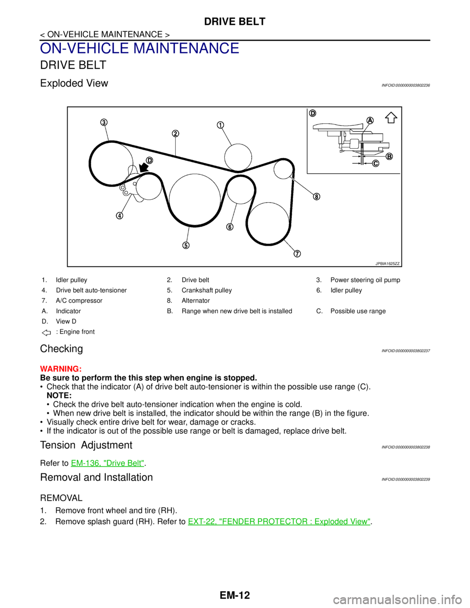
Exploded ViewINFOID:0000000003802236
CheckingINFOID:0000000003802237
WARNING:
Be sure to perform the this step when engine is stopped.
Check that the indicator (A) of drive belt auto-tensioner is within the possible use range (C).
NOTE:
Check the drive belt auto-tensioner indication when the engine is cold.
When new drive belt is installed, the indicator should be within the range (B) in the figure.
Visually check entire drive belt for wear, damage or cracks.
If the indicator is out of the possible use range or belt is damaged, replace drive belt.
Tension AdjustmentINFOID:0000000003802238
Refer to EM-136, "Drive Belt".
Removal and InstallationINFOID:0000000003802239
REMOVAL
1. Remove front wheel and tire (RH).
2. Remove splash guard (RH). Refer to EXT-22, "
FENDER PROTECTOR : Exploded View".
JPBIA1625ZZ
1. Idler pulley 2. Drive belt 3. Power steering oil pump
4. Drive belt auto-tensioner 5. Crankshaft pulley 6. Idler pulley
7. A/C compressor 8. Alternator
A. Indicator B. Range when new drive belt is installed C. Possible use range
D. View D
: Engine front
Page 1913 of 5121
EM-38
< ON-VEHICLE REPAIR >
OIL PAN AND OIL STRAINER
OIL PAN AND OIL STRAINER
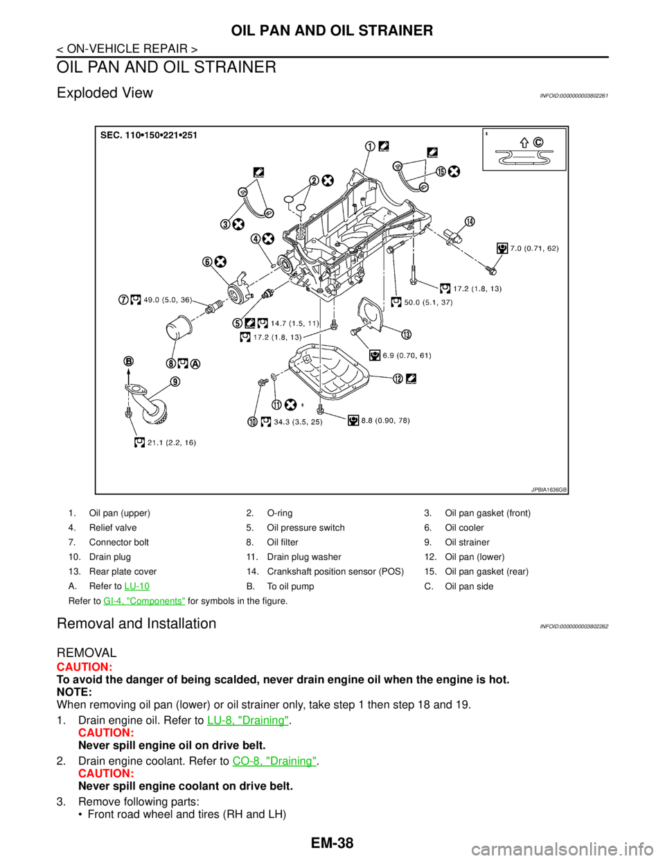
Exploded ViewINFOID:0000000003802261
Removal and InstallationINFOID:0000000003802262
REMOVAL
CAUTION:
To avoid the danger of being scalded, never drain engine oil when the engine is hot.
NOTE:
When removing oil pan (lower) or oil strainer only, take step 1 then step 18 and 19.
1. Drain engine oil. Refer to LU-8, "
Draining".
CAUTION:
Never spill engine oil on drive belt.
2. Drain engine coolant. Refer to CO-8, "
Draining".
CAUTION:
Never spill engine coolant on drive belt.
3. Remove following parts:
Front road wheel and tires (RH and LH)
1. Oil pan (upper) 2. O-ring 3. Oil pan gasket (front)
4. Relief valve 5. Oil pressure switch 6. Oil cooler
7. Connector bolt 8. Oil filter 9. Oil strainer
10. Drain plug 11. Drain plug washer 12. Oil pan (lower)
13. Rear plate cover 14. Crankshaft position sensor (POS) 15. Oil pan gasket (rear)
A. Refer to LU-10
B. To oil pump C. Oil pan side
Refer to GI-4, "
Components" for symbols in the figure.
JPBIA1636GB
Page 1943 of 5121
EM-68
< REMOVAL AND INSTALLATION >
ENGINE ASSEMBLY
Place chocks at front and back of rear wheels.
For engines not equipped with engine slingers, attach proper slingers and bolts described in PARTS
CATALOG.
CAUTION:
Always be careful to work safely, avoid forceful or uninstructed operations.
Never start working until exhaust system and engine coolant are cool enough.
If items or work required are not covered by the engine section, refer to the applicable sections.
Always use the support point specified for lifting.
Use either 2-pole lift type or separate type lift as best you can. If board-on type is used for unavoid-
able reasons, support at the rear axle jacking point with transmission jack or similar tool before
starting work, in preparation for the backward shift of center of gravity.
For supporting points for lifting and jacking point at rear axle, refer to GI-30, "
Garage Jack and
Safety Stand and 2-Pole Lift".
REMOVAL
Outline
At first, remove the engine and the transaxle assembly with front suspension member downward. Then sepa-
rate the engine and the transaxle.
Preparation
1. Release fuel pressure. Refer to EC-411, "Inspection".
2. Drain engine coolant. Refer to CO-8, "
Draining".
CAUTION:
Perform this step when the engine is cold.
Never spill engine coolant on drive belt.
3. Remove the following parts:
Engine cover: Refer to EM-24, "
Exploded View".
Front road wheel and tires
Splash guards (RH and LH): Refer to EXT-22, "
FENDER PROTECTOR : Exploded View".
Air duct (inlet), air cleaner cases (upper and lower) with mass air flow sensor and air duct assembly:
Refer to EM-26, "
Exploded View".
Battery and battery tray: Refer to PG-109, "
Removal and Installation".
Drive belt: Refer to EM-12, "
Removal and Installation".
Reservoir tank of radiator. Refer to CO-13, "
Exploded View".
Front wiper arm: Refer to WW-105, "
Exploded View".
4. Disconnect engine room harness at the TCM, ECM and other sides.
CAUTION:
To keep clean harness connector and avoid damage and foreign materials, cover them completely
with plastic bags or something similar.
5. Remove battery bracket with ECM and TCM.
6. Remove extension cowl top. Refer to EXT-20, "
Exploded View".
Engine Room
1. Disconnect heater hoses. Refer to CO-25, "Exploded View".
Install plug to avoid leakage of engine coolant.
2. Remove EVAP hose. Refer to EM-28, "
Exploded View".
3. Disconnect fuel feed hose quick connector at fuel tube side. Refer to EM-44, "
Exploded View".
Install plug to avoid leakage of fuel.
4. Disconnect transaxle shift control cable at transaxle side. Refer to TM-319, "
Exploded View" (VQ25DE) or
TM-157, "
Exploded View" (VQ35DE).
5. Disconnect brake booster vacuum hose at engine side. Refer to EM-28, "
Exploded View".
6. Disconnect ground cable.
7. Disconnect A/C compressor piping at A/C compressor side. Refer to HA-36, "
Exploded View".
8. Disconnect suction hoses of power steering oil pump at reservoir tank side. Refer to ST-34, "
Exploded
View".
Install plug to avoid leakage of power steering fluid.
9. Disconnect CVT fluid cooler hoses from radiator. Refer to CO-13, "
Exploded View".
Page 1944 of 5121
ENGINE ASSEMBLY
EM-69
< REMOVAL AND INSTALLATION >
C
D
E
F
G
H
I
J
K
L
MA
EM
N
P O
10. Remove starter motor. Refer to STR-15, "VQ25DE : Exploded View" (VQ25DE) or STR-20, "VQ35DE :
Exploded View" (VQ35DE).
Vehicle Underbody
1. Remove front drive shafts (RH and LH). Refer to FAX-16, "Exploded View".
2. Remove exhaust front tube. Refer to EX-5, "
Exploded View".
3. Remove heat insulator.
4. Disconnect steering lower joint at power steering gear assembly side, and release steering lower shaft.
Refer to ST-16, "
Exploded View".
5. Disconnect front stabilizer connecting rod. Refer to FSU-14, "
Exploded View".
6. Remove strut assembly and steering knuckle fixing nuts and bolts. Refer to FSU-9, "
Exploded View" and
FA X - 8 , "
Exploded View".
7. Remove front wheel sensor (RH and LH) for ABS from steering knuckle. Refer to BRC-57, "
FRONT
WHEEL SENSOR : Exploded View".
8. Remove front brake caliper assembly with piping connected, and temporarily secure it to aside for vehicle
side. Refer to BR-34, "
BRAKE CALIPER ASSEMBLY : Exploded View".
9. Disconnect power steering piping at a point between vehicle and engine. Refer to ST-34, "
Exploded
View".
Install plug to avoid leakage of power steering fluid.
10. Remove rear plate cover from oil pan (upper). Then remove bolts fixing drive plate to torque converter.
Refer to EM-38, "
Exploded View" and TM-332, "Removal and Installation" (VQ25DE) or TM-168,
"Removal and Installation" (VQ35DE).
11. Remove transaxle joint bolts which pierce at oil pan (upper) lower rear side. Refer to EM-38, "
Exploded
View".
12. Remove crankshaft position sensor (POS). Refer to EM-38, "
Exploded View".
CAUTION:
Handle carefully to avoid dropping and shocks.
Never disassemble.
Never allow metal powder to adhere to magnetic part at sensor tip.
Never place sensors in a location where they are exposed to magnetism.
Removal
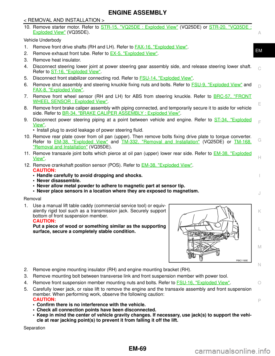
1. Use a manual lift table caddy (commercial service tool) or equiv-
alently rigid tool such as a transmission jack. Securely support
bottom of front suspension member.
CAUTION:
Put a piece of wood or something similar as the supporting
surface, secure a completely stable condition.
2. Remove engine mounting insulator (RH) and engine mounting bracket (RH).
3. Remove mounting bolt between transverse link and front suspension member with power tool.
4. Remove front suspension member mounting nuts and bolts. Refer to FSU-16, "
Exploded View".
5. Carefully lower jack, or raise lift to remove the engine and the transaxle assembly and front suspension
member. When performing work, observe the following caution:
CAUTION:
Confirm there is no interference with the vehicle.
Check all connection points have been disconnected.
Keep in mind the center of vehicle gravity changes. If necessary, use jack(s) to support the vehi-
cle at rear jacking point(s) to prevent it from falling it off the lift.
Separation
PBIC1190E
Page 1969 of 5121
EM-94
< DISASSEMBLY AND ASSEMBLY >
OIL SEAL
1. Remove the following parts:
Road wheel and tire (RH)
Splash guard (RH): Refer to EXT-22, "
FENDER PROTECTOR : Exploded View".
Drive belt: Refer to EM-12, "
Removal and Installation".
Crankshaft pulley: Refer to EM-52, "
Exploded View".
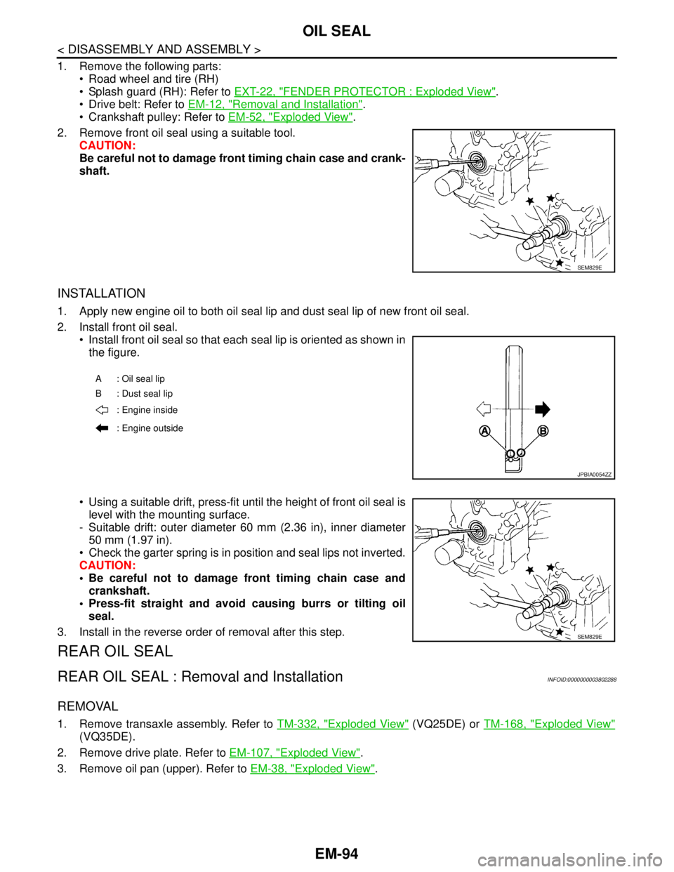
2. Remove front oil seal using a suitable tool.
CAUTION:
Be careful not to damage front timing chain case and crank-
shaft.
INSTALLATION
1. Apply new engine oil to both oil seal lip and dust seal lip of new front oil seal.
2. Install front oil seal.
Install front oil seal so that each seal lip is oriented as shown in
the figure.
Using a suitable drift, press-fit until the height of front oil seal is
level with the mounting surface.
- Suitable drift: outer diameter 60 mm (2.36 in), inner diameter
50 mm (1.97 in).
Check the garter spring is in position and seal lips not inverted.
CAUTION:
Be careful not to damage front timing chain case and
crankshaft.
Press-fit straight and avoid causing burrs or tilting oil
seal.
3. Install in the reverse order of removal after this step.
REAR OIL SEAL
REAR OIL SEAL : Removal and InstallationINFOID:0000000003802288
REMOVAL
1. Remove transaxle assembly. Refer to TM-332, "Exploded View" (VQ25DE) or TM-168, "Exploded View"
(VQ35DE).
2. Remove drive plate. Refer to EM-107, "
Exploded View".
3. Remove oil pan (upper). Refer to EM-38, "
Exploded View".
SEM829E
A: Oil seal lip
B : Dust seal lip
: Engine inside
: Engine outside
JPBIA0054ZZ
SEM829E