2008 NISSAN TEANA wheel
[x] Cancel search: wheelPage 2452 of 5121
FAX-24
< ON-VEHICLE REPAIR >
FRONT DRIVE SHAFT
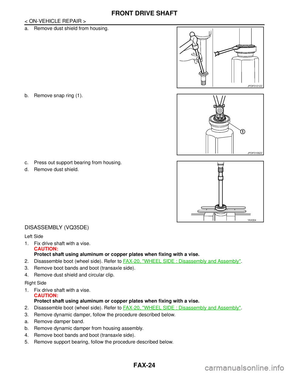
a. Remove dust shield from housing.
b. Remove snap ring (1).
c. Press out support bearing from housing.
d. Remove dust shield.
DISASSEMBLY (VQ35DE)
Left Side
1. Fix drive shaft with a vise.
CAUTION:
Protect shaft using aluminum or copper plates when fixing with a vise.
2. Disassemble boot (wheel side). Refer to FAX-20, "
WHEEL SIDE : Disassembly and Assembly".
3. Remove boot bands and boot (transaxle side).
4. Remove dust shield and circular clip.
Right Side
1. Fix drive shaft with a vise.
CAUTION:
Protect shaft using aluminum or copper plates when fixing with a vise.
2. Disassemble boot (wheel side). Refer to FAX-20, "
WHEEL SIDE : Disassembly and Assembly".
3. Remove dynamic damper, follow the procedure described below.
a. Remove damper band.
b. Remove dynamic damper from housing assembly.
4. Remove boot bands and boot (transaxle side).
5. Remove support bearing, follow the procedure described below.
JPDIF0121ZZ
JPDIF0106ZZ
YA X 0 0 4
Page 2459 of 5121
FRONT DRIVE SHAFT
FAX-31
< ON-VEHICLE REPAIR >
C
E
F
G
H
I
J
K
L
MA
B
FA X
N
O
P
Never reuse dust shield.
3. Install circular clip.
CAUTION:
Never reuse circular clip.
4. Apply balance of the specified amount grease to housing assembly.
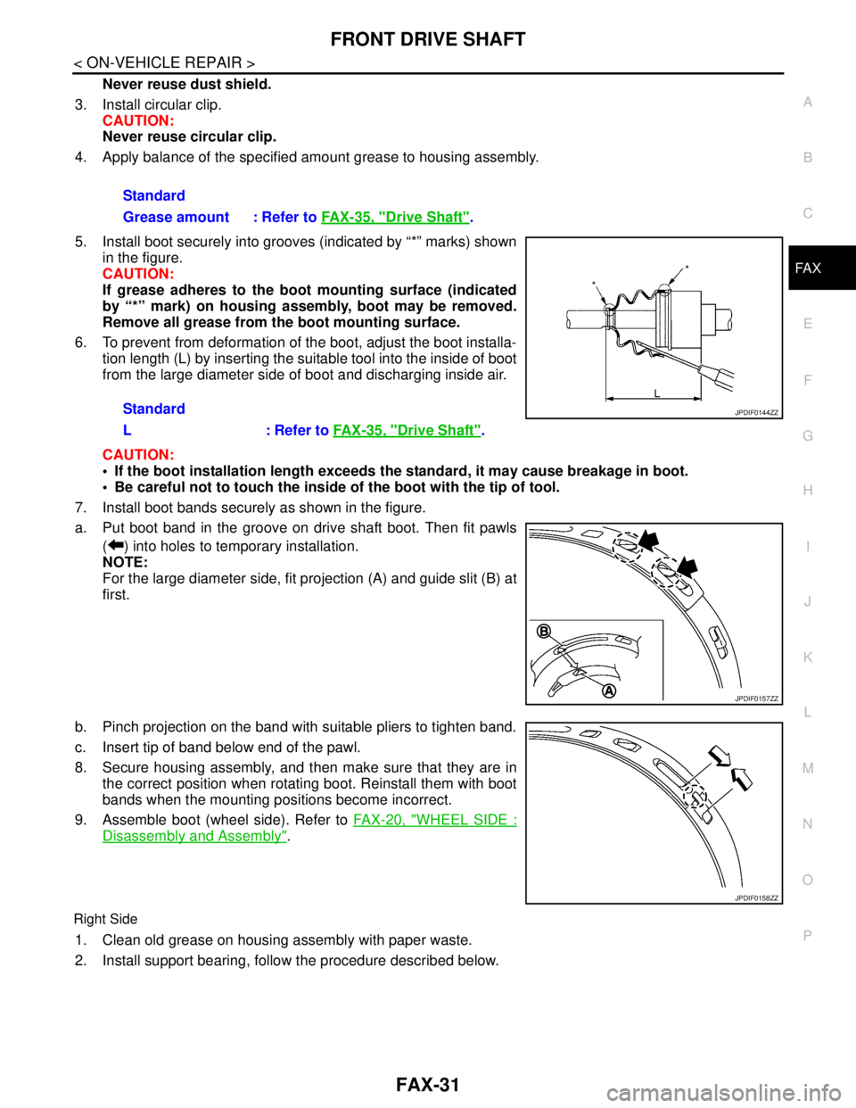
5. Install boot securely into grooves (indicated by “*” marks) shown
in the figure.
CAUTION:
If grease adheres to the boot mounting surface (indicated
by “*” mark) on housing assembly, boot may be removed.
Remove all grease from the boot mounting surface.
6. To prevent from deformation of the boot, adjust the boot installa-
tion length (L) by inserting the suitable tool into the inside of boot
from the large diameter side of boot and discharging inside air.
CAUTION:
If the boot installation length exceeds the standard, it may cause breakage in boot.
Be careful not to touch the inside of the boot with the tip of tool.
7. Install boot bands securely as shown in the figure.
a. Put boot band in the groove on drive shaft boot. Then fit pawls
( ) into holes to temporary installation.
NOTE:
For the large diameter side, fit projection (A) and guide slit (B) at
first.
b. Pinch projection on the band with suitable pliers to tighten band.
c. Insert tip of band below end of the pawl.
8. Secure housing assembly, and then make sure that they are in
the correct position when rotating boot. Reinstall them with boot
bands when the mounting positions become incorrect.
9. Assemble boot (wheel side). Refer to FAX-20, "
WHEEL SIDE :
Disassembly and Assembly".
Right Side
1. Clean old grease on housing assembly with paper waste.
2. Install support bearing, follow the procedure described below. Standard
Grease amount : Refer to FAX-35, "
Drive Shaft".
Standard
L : Refer to FAX-35, "
Drive Shaft".
JPDIF0144ZZ
JPDIF0157ZZ
JPDIF0158ZZ
Page 2461 of 5121
FRONT DRIVE SHAFT
FAX-33
< ON-VEHICLE REPAIR >
C
E
F
G
H
I
J
K
L
MA
B
FA X
N
O
P
CAUTION:
If the boot installation length exceeds the standard, it may cause breakage in boot.
Be careful not to touch the inside of the boot with the tip of tool.
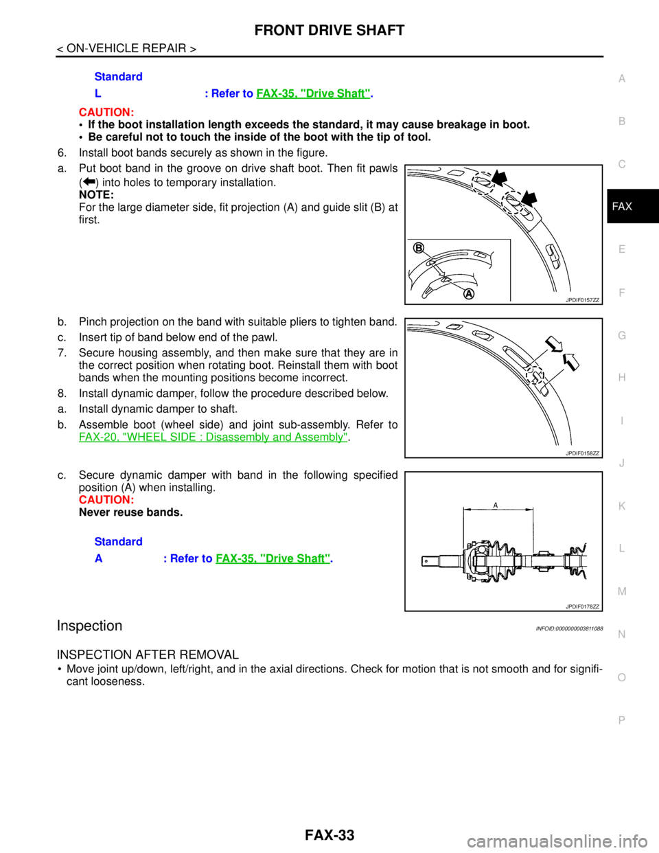
6. Install boot bands securely as shown in the figure.
a. Put boot band in the groove on drive shaft boot. Then fit pawls
( ) into holes to temporary installation.
NOTE:
For the large diameter side, fit projection (A) and guide slit (B) at
first.
b. Pinch projection on the band with suitable pliers to tighten band.
c. Insert tip of band below end of the pawl.
7. Secure housing assembly, and then make sure that they are in
the correct position when rotating boot. Reinstall them with boot
bands when the mounting positions become incorrect.
8. Install dynamic damper, follow the procedure described below.
a. Install dynamic damper to shaft.
b. Assemble boot (wheel side) and joint sub-assembly. Refer to
FAX-20, "
WHEEL SIDE : Disassembly and Assembly".
c. Secure dynamic damper with band in the following specified
position (A) when installing.
CAUTION:
Never reuse bands.
InspectionINFOID:0000000003811088
INSPECTION AFTER REMOVAL
Move joint up/down, left/right, and in the axial directions. Check for motion that is not smooth and for signifi-
cant looseness.Standard
L : Refer to FAX-35, "
Drive Shaft".
JPDIF0157ZZ
JPDIF0158ZZ
Standard
A : Refer to FAX-35, "
Drive Shaft".
JPDIF0178ZZ
Page 2462 of 5121
FAX-34
< ON-VEHICLE REPAIR >
FRONT DRIVE SHAFT
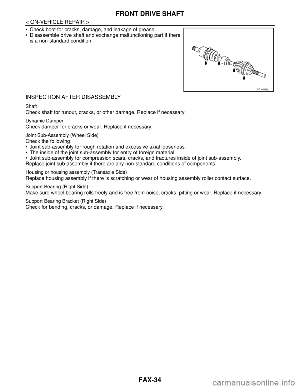
Check boot for cracks, damage, and leakage of grease.
Disassemble drive shaft and exchange malfunctioning part if there
is a non-standard condition.
INSPECTION AFTER DISASSEMBLY
Shaft
Check shaft for runout, cracks, or other damage. Replace if necessary.
Dynamic Damper
Check damper for cracks or wear. Replace if necessary.
Joint Sub-Assembly (Wheel Side)
Check the following:
Joint sub-assembly for rough rotation and excessive axial looseness.
The inside of the joint sub-assembly for entry of foreign material.
Joint sub-assembly for compression scars, cracks, and fractures inside of joint sub-assembly.
Replace joint sub-assembly if there are any non-standard conditions of components.
Housing or housing assembly (Transaxle Side)
Replace housing assembly if there is scratching or wear of housing assembly roller contact surface.
Support Bearing (Right Side)
Make sure wheel bearing rolls freely and is free from noise, cracks, pitting or wear. Replace if necessary.
Support Bearing Bracket (Right Side)
Check for bending, cracks, or damage. Replace if necessary.
SDIA1190J
Page 2463 of 5121
SERVICE DATA AND SPECIFICATIONS (SDS)
FAX-35
< SERVICE DATA AND SPECIFICATIONS (SDS)
C
E
F
G
H
I
J
K
L
MA
B
FA X
N
O
P
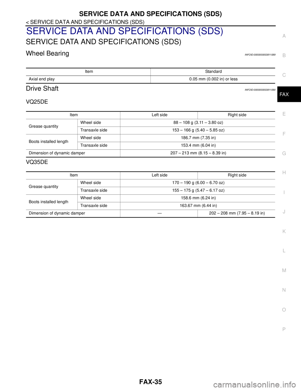
SERVICE DATA AND SPECIFICATIONS (SDS)
SERVICE DATA AND SPECIFICATIONS (SDS)
Wheel BearingINFOID:0000000003811089
Drive ShaftINFOID:0000000003811090
VQ25DE
VQ35DE
Item Standard
Axial end play0.05 mm (0.002 in) or less
Item Left side Right side
Grease quantityWheel side 88 – 108 g (3.11 – 3.80 oz)
Transaxle side 153 – 166 g (5.40 – 5.85 oz)
Boots installed lengthWheel side 186.7 mm (7.35 in)
Transaxle side 153.4 mm (6.04 in)
Dimension of dynamic damper 207 – 213 mm (8.15 – 8.39 in)
Item Left side Right side
Grease quantityWheel side 170 – 190 g (6.00 – 6.70 oz)
Transaxle side 155 – 175 g (5.47 – 6.17 oz)
Boots installed lengthWheel side 158.6 mm (6.24 in)
Transaxle side 163.67 mm (6.44 in)
Dimension of dynamic damper — 202 – 208 mm (7.95 – 8.19 in)
Page 2475 of 5121

FSU-1
SUSPENSION
C
DF
G H
I
J
K L
M
SECTION FSU
A
B
FSU
N
O PCONTENTS
FRONT SUSPENSION
SYMPTOM DIAGNOSIS ..... ..........................2
NOISE, VIBRATION AND HARSHNESS
(NVH) TROUBLESHOOTING ........................ .....
2
NVH Troubleshooting Chart ................................ ......2
PRECAUTION ...............................................3
PRECAUTIONS .............................................. .....3
Precaution for Supplemental Restraint System
(SRS) "AIR BAG" and "SEAT BELT PRE-TEN-
SIONER" ............................................................. ......
3
Precaution Necessary for Steering Wheel Rota-
tion after Battery Disconnect .....................................
3
Precaution for Procedure without Cowl Top Cover ......4
Precautions for Suspension ......................................4
PREPARATION ............................................5
PREPARATION .............................................. .....5
Special Service Tool ........................................... ......5
Commercial Service Tool ..........................................5
ON-VEHICLE MAINTENANCE .....................6
FRONT SUSPENSION ASSEMBLY .............. .....6
Inspection ............................................................ ......6
WHEEL ALIGNMENT ..........................................7
Wheel Alignment Inspection ................................ ......7
ON-VEHICLE REPAIR ..................................9
FRONT COIL SPRING AND STRUT .................9
Exploded View ..................................................... .....9
Removal and Installation ..........................................9
Disassembly and Assembly .....................................10
Inspection ................................................................11
TRANSVERSE LINK .........................................12
Exploded View ..................................................... ....12
Removal and Installation .........................................12
Inspection ................................................................12
FRONT STABILIZER ........................................14
Exploded View .........................................................14
Removal and Installation .........................................14
Inspection ................................................................15
REMOVAL AND INSTALLATION ...............16
FRONT SUSPENSION MEMBER .....................16
Exploded View ..................................................... ....16
Removal and Installation .........................................16
Inspection ................................................................17
SERVICE DATA AND SPECIFICATIONS
(SDS) ............... .............................................
18
SERVICE DATA AND SPECIFICATIONS
(SDS) .................................................................
18
Wheel Alignment ................................................. ....18
Ball Joint ..................................................................18
Wheel Height ...........................................................18
Page 2476 of 5121
FSU-2
< SYMPTOM DIAGNOSIS >
NOISE, VIBRATION AND HARSHNESS (NVH) TROUBLESHOOTING
SYMPTOM DIAGNOSIS
NOISE, VIBRATION AND HARSHNESS (NVH) TROUBLESHOOTING
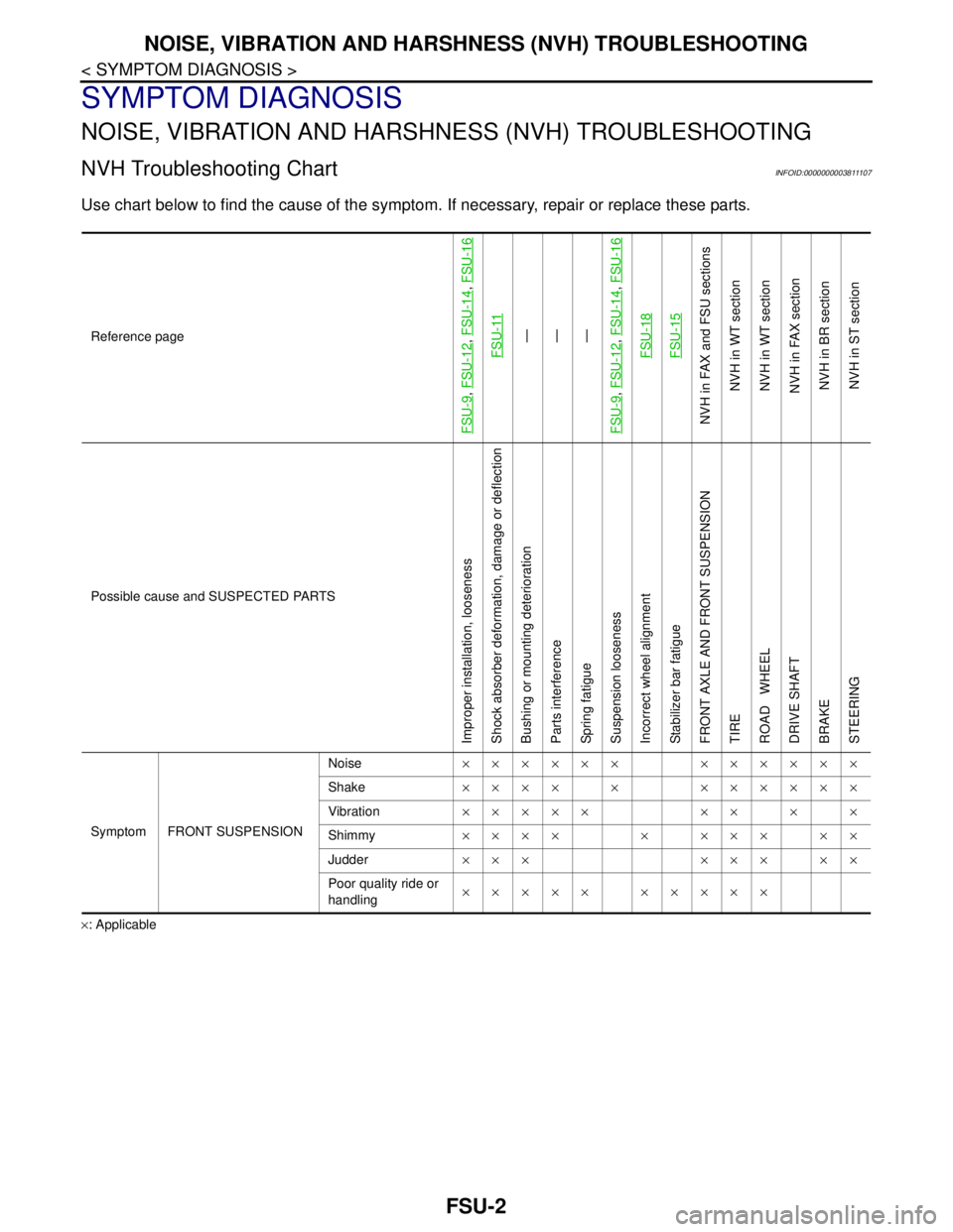
NVH Troubleshooting ChartINFOID:0000000003811107
Use chart below to find the cause of the symptom. If necessary, repair or replace these parts.
×: ApplicableReference page
FSU-9
, FSU-12
, FSU-14
, FSU-16
FSU-11
—
—
—
FSU-9
, FSU-12
, FSU-14
, FSU-16
FSU-18FSU-15
NVH in FAX and FSU sections
NVH in WT section
NVH in WT section
NVH in FAX section
NVH in BR section
NVH in ST section
Possible cause and SUSPECTED PARTS
Improper installation, looseness
Shock absorber deformation, damage or deflection
Bushing or mounting deterioration
Parts interference
Spring fatigue
Suspension looseness
Incorrect wheel alignment
Stabilizer bar fatigue
FRONT AXLE AND FRONT SUSPENSION
TIRE
ROAD WHEEL
DRIVE SHAFT
BRAKE
STEERING
Symptom FRONT SUSPENSIONNoise×××××× ××××××
Shake×××× × ××××××
Vibration××××× ×× × ×
Shimmy×××× × ××× ××
Judder ××× ××× ××
Poor quality ride or
handling××××× ×××××
Page 2477 of 5121
PRECAUTIONS
FSU-3
< PRECAUTION >
C
D
F
G
H
I
J
K
L
MA
B
FSU
N
O
P
PRECAUTION
PRECAUTIONS
Precaution for Supplemental Restraint System (SRS) "AIR BAG" and "SEAT BELT
PRE-TENSIONER"
INFOID:0000000003890155
The Supplemental Restraint System such as “AIR BAG” and “SEAT BELT PRE-TENSIONER”, used along
with a front seat belt, helps to reduce the risk or severity of injury to the driver and front passenger for certain
types of collision. Information necessary to service the system safely is included in the “SRS AIRBAG” and
“SEAT BELT” of this Service Manual.
WARNING:
• To avoid rendering the SRS inoperative, which could increase the risk of personal injury or death in
the event of a collision which would result in air bag inflation, all maintenance must be performed by
an authorized NISSAN/INFINITI dealer.
Improper maintenance, including incorrect removal and installation of the SRS, can lead to personal
injury caused by unintentional activation of the system. For removal of Spiral Cable and Air Bag
Module, see the “SRS AIRBAG”.
Never use electrical test equipment on any circuit related to the SRS unless instructed to in this Ser-
vice Manual. SRS wiring harnesses can be identified by yellow and/or orange harnesses or harness
connectors.
Precaution Necessary for Steering Wheel Rotation after Battery Disconnect
INFOID:0000000003890156
NOTE:
Before removing and installing any control units, first turn the push-button ignition switch to the LOCK posi-
tion, then disconnect both battery cables.
After finishing work, confirm that all control unit connectors are connected properly, then re-connect both
battery cables.
Always use CONSULT-III to perform self-diagnosis as a part of each function inspection after finishing work.
If a DTC is detected, perform trouble diagnosis according to self-diagnosis results.
This vehicle is equipped with a push-button ignition switch and a steering lock unit.
If the battery is disconnected or discharged, the steering wheel will lock and cannot be turned.
If turning the steering wheel is required with the battery disconnected or discharged, follow the procedure
below before starting the repair operation.
OPERATION PROCEDURE
1. Connect both battery cables.
NOTE:
Supply power using jumper cables if battery is discharged.
2. Turn the push-button ignition switch to ACC position.
(At this time, the steering lock will be released.)
3. Disconnect both battery cables. The steering lock will remain released with both battery cables discon-
nected and the steering wheel can be turned.
4. Perform the necessary repair operation.
5. When the repair work is completed, re-connect both battery cables. With the brake pedal released, turn
the push-button ignition switch from ACC position to ON position, then to LOCK position. (The steering
wheel will lock when the push-button ignition switch is turned to LOCK position.)
6. Perform self-diagnosis check of all control units using CONSULT-III.