2008 NISSAN TEANA wheel
[x] Cancel search: wheelPage 2487 of 5121
TRANSVERSE LINK
FSU-13
< ON-VEHICLE REPAIR >
C
D
F
G
H
I
J
K
L
MA
B
FSU
N
O
P
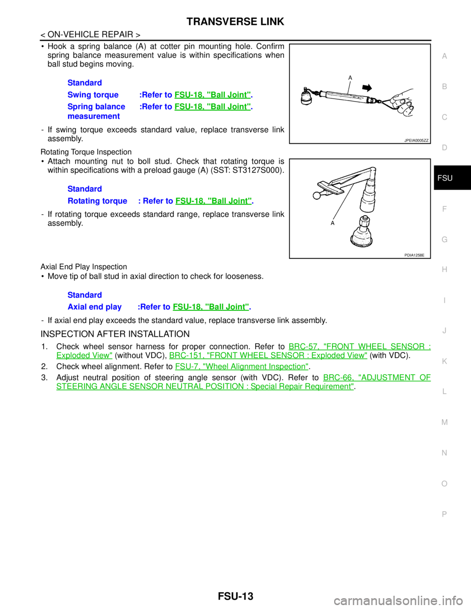
Hook a spring balance (A) at cotter pin mounting hole. Confirm
spring balance measurement value is within specifications when
ball stud begins moving.
- If swing torque exceeds standard value, replace transverse link
assembly.
Rotating Torque Inspection
Attach mounting nut to boll stud. Check that rotating torque is
within specifications with a preload gauge (A) (SST: ST3127S000).
- If rotating torque exceeds standard range, replace transverse link
assembly.
Axial End Play Inspection
Move tip of ball stud in axial direction to check for looseness.
- If axial end play exceeds the standard value, replace transverse link assembly.
INSPECTION AFTER INSTALLATION
1. Check wheel sensor harness for proper connection. Refer to BRC-57, "FRONT WHEEL SENSOR :
Exploded View" (without VDC), BRC-151, "FRONT WHEEL SENSOR : Exploded View" (with VDC).
2. Check wheel alignment. Refer to FSU-7, "
Wheel Alignment Inspection".
3. Adjust neutral position of steering angle sensor (with VDC). Refer to BRC-66, "
ADJUSTMENT OF
STEERING ANGLE SENSOR NEUTRAL POSITION : Special Repair Requirement". Standard
Swing torque :Refer to FSU-18, "
Ball Joint".
Spring balance
measurement:Refer to FSU-18, "
Ball Joint".
JPEIA0005ZZ
Standard
Rotating torque : Refer to FSU-18, "
Ball Joint".
PDIA1258E
Standard
Axial end play :Refer to FSU-18, "
Ball Joint".
Page 2490 of 5121
FSU-16
< REMOVAL AND INSTALLATION >
FRONT SUSPENSION MEMBER
REMOVAL AND INSTALLATION
FRONT SUSPENSION MEMBER
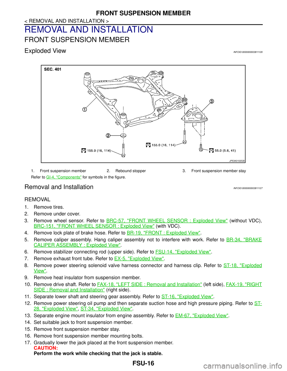
Exploded ViewINFOID:0000000003811126
Removal and InstallationINFOID:0000000003811127
REMOVAL
1. Remove tires.
2. Remove under cover.
3. Remove wheel sensor. Refer to BRC-57, "
FRONT WHEEL SENSOR : Exploded View" (without VDC),
BRC-151, "
FRONT WHEEL SENSOR : Exploded View" (with VDC).
4. Remove lock plate of brake hose. Refer to BR-19, "
FRONT : Exploded View".
5. Remove caliper assembly. Hang caliper assembly not to interfere with work. Refer to BR-34, "
BRAKE
CALIPER ASSEMBLY : Exploded View".
6. Remove stabilizer connecting rod (upper side). Refer to FSU-14, "
Exploded View".
7. Remove exhaust front tube. Refer to EX-5, "
Exploded View".
8. Remove power steering solenoid valve harness connector and harness clip. Refer to ST-18, "
Exploded
View".
9. Remove heat insulator from suspension member.
10. Remove drive shaft. Refer to FAX-18, "
LEFT SIDE : Removal and Installation" (left side), FAX-19, "RIGHT
SIDE : Removal and Installation" (right side).
11. Separate lower shaft and steering gear assembly. Refer to ST-16, "
Exploded View".
12. Remove power steering oil pump and then separate suction hose and high pressure piping. Refer to ST-
28, "Exploded View", ST-34, "Exploded View".
13. Separate engine mount insulator from engine assembly. Refer to EM-67, "
Exploded View".
14. Set suitable jack to front suspension member.
15. Remove front suspension member stay.
16. Remove front suspension member mounting bolts.
17. Gradually lower the jack placed at the front suspension member.
CAUTION:
Perform the work while checking that the jack is stable.
1. Front suspension member 2. Rebound stopper 3. Front suspension member stay
Refer to GI-4, "
Components" for symbols in the figure.
JPEIA0102GB
Page 2491 of 5121
FRONT SUSPENSION MEMBER
FSU-17
< REMOVAL AND INSTALLATION >
C
D
F
G
H
I
J
K
L
MA
B
FSU
N
O
P
NOTE:
Remove the steering knuckle and wheel bearing assembly, steering gear assembly and hydraulic line,
stabilizer bar, transverse link and engine mounting insulator as a unit from the vehicle.
18. Remove the following parts.
Steering knuckle and wheel hub and bearing assembly: refer to FA X - 8 , "
Exploded View".
Steering gear assembly and hydraulic line: refer to ST-18, "
Exploded View" and ST-34, "Exploded
View".
Stabilizer bar: refer to FSU-14, "
Exploded View".
Transverse link: refer to FSU-12, "
Exploded View".
Engine mounting insulator: refer to EM-67, "
Exploded View".
INSTALLATION
Note the following, and install in the reverse order of removal.
Perform final tightening of installation position between front suspension member and transverse links (rub-
ber bushing) under unladen condition with tires on level ground.
InspectionINFOID:0000000003811128
INSPECTION AFTER REMOVAL
Check the front suspension member for significant deformation, cracks, or damages. Replace if necessary.
INSPECTION AFTER INSTALLATION
1. Check wheel sensor harness for proper connection. Refer to BRC-57, "FRONT WHEEL SENSOR :
Exploded View" (without VDC), BRC-151, "FRONT WHEEL SENSOR : Exploded View" (with VDC).
2. Check wheel alignment. Refer to FSU-7, "
Wheel Alignment Inspection".
3. Adjust the neutral position of the steering angle sensor. Refer to BRC-66, "
ADJUSTMENT OF STEERING
ANGLE SENSOR NEUTRAL POSITION : Special Repair Requirement".
Page 2492 of 5121
FSU-18
< SERVICE DATA AND SPECIFICATIONS (SDS)
SERVICE DATA AND SPECIFICATIONS (SDS)
SERVICE DATA AND SPECIFICATIONS (SDS)
SERVICE DATA AND SPECIFICATIONS (SDS)
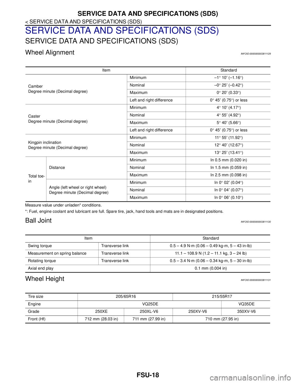
Wheel AlignmentINFOID:0000000003811129
Measure value under unladen* conditions.
*: Fuel, engine coolant and lubricant are full. Spare tire, jack, hand tools and mats are in designated positions.
Ball JointINFOID:0000000003811130
Wheel HeightINFOID:0000000003811131
Item Standard
Camber
Degree minute (Decimal degree)Minimum –1° 10′ (–1.16°)
Nominal –0° 25′ (–0.42°)
Maximum 0° 20′ (0.33°)
Left and right difference 0° 45′ (0.75°) or less
Caster
Degree minute (Decimal degree)Minimum 4° 10′ (4.17°)
Nominal 4° 55′ (4.92°)
Maximum 5° 40′ (5.66°)
Left and right difference 0° 45′ (0.75°) or less
Kingpin inclination
Degree minute (Decimal degree)Minimum 11° 55′ (11.92°)
Nominal 12° 40′ (12.67°)
Maximum 13° 25′ (13.41°)
To t a l t o e -
inDistanceMinimum In 0.5 mm (0.020 in)
Nominal In 1.5 mm (0.059 in)
Maximum In 2.5 mm (0.098 in)
Angle (left wheel or right wheel)
Degree minute (Decimal degree)Minimum In 0° 02′ (0.04°)
Nominal In 0° 04
′ (0.07°)
Maximum In 0° 06′ (0.10°)
Item Standard
Swing torque Transverse link 0.5 – 4.9 N·m (0.06 – 0.49 kg-m, 5 – 43 in-lb)
Measurement on spring balance Transverse link 11.1 – 108.9 N (1.2 – 11.1 kg, 3 – 24 lb)
Rotating torque Transverse link 0.5 – 3.4 N·m (0.06 – 0.34 kg-m, 5 – 30 in-lb)
Axial end play0.1 mm (0.004 in)
Tire size 205/65R16 215/55R17
Engine VQ25DE VQ35DE
Grade 250XE 250XL-V6 250XV-V6 350XV-V6
Front (Hf) 712 mm (28.03 in) 711 mm (27.99 in) 710 mm (27.95 in)
Page 2494 of 5121

GI-1
GENERAL INFORMATION
C
D
E
F
G
H
I
J
K
L
MB
GI
SECTION GI
N
O
P
CONTENTS
GENERAL INFORMATION
HOW TO USE THIS MANUAL ......................3
HOW TO USE THIS MANUAL ............................3
Description ................................................................3
Terms ........................................................................3
Units ..........................................................................3
Contents ....................................................................3
Relation between Illustrations and Descriptions .......4
Components ..............................................................4
HOW TO FOLLOW TROUBLE DIAGNOSES .....6
Description ................................................................6
How to Follow Test Groups in Trouble Diagnosis ......6
Key to Symbols Signifying Measurements or Pro-
cedures .....................................................................
7
HOW TO READ WIRING DIAGRAMS ................9
Connector Symbols ...................................................9
Sample/Wiring Diagram -Example- .........................10
Description ..............................................................11
ABBREVIATIONS ..............................................13
Abbreviation List ......................................................13
TIGHTENING TORQUE OF STANDARD
BOLTS ................................................................
14
Description ..............................................................14
Tightening Torque Table (New Standard Includ-
ed) ...........................................................................
14
TERMINOLOGY .................................................17
SAE J1930 Terminology List ...................................17
FEATURES OF NEW MODEL .....................21
IDENTIFICATION INFORMATION .....................21
Model Variation .......................................................21
Information About Identification or Model Code ......21
Dimensions .............................................................23
Wheels & Tires ........................................................23
PRECAUTION ..............................................24
PRECAUTIONS .................................................24
Description ...............................................................24
Precaution for Supplemental Restraint System
(SRS) "AIR BAG" and "SEAT BELT PRE-TEN-
SIONER" .................................................................
24
Precautions For Xenon Headlamp Service .............24
Precaution Necessary for Steering Wheel Rota-
tion after Battery Disconnect ...................................
24
Precaution for Procedure without Cowl Top Cover ....25
General Precautions ................................................25
Three Way Catalyst .................................................27
Multiport Fuel Injection System or Engine Control
System .....................................................................
27
Hoses ......................................................................27
Engine Oils ..............................................................28
Air Conditioning .......................................................28
Fuel ..........................................................................29
LIFTING POINT .................................................30
Commercial Service Tools .......................................30
Garage Jack and Safety Stand and 2-Pole Lift .......30
Board-On Lift ...........................................................31
TOW TRUCK TOWING .....................................32
Tow Truck Towing ...................................................32
Vehicle Recovery (Freeing a Stuck Vehicle) ...........32
BASIC INSPECTION ...................................34
SERVICE INFORMATION FOR ELECTRICAL
INCIDENT ..........................................................
34
Work Flow ................................................................34
Control Units and Electrical Parts ............................34
Intermittent Incident .................................................35
Circuit Inspection .....................................................37
CONSULT-III/GST CHECKING SYSTEM .........43
Description ...............................................................43
CONSULT-III Function and System Application*1 ....43
CONSULT-III/GST Data Link Connector (DLC)
Circuit ......................................................................
43
Page 2506 of 5121

ABBREVIATIONS
GI-13
< HOW TO USE THIS MANUAL >
C
D
E
F
G
H
I
J
K
L
MB
GI
N
O
PABBREVIATIONS
Abbreviation ListINFOID:0000000003852769
The following ABBREVIATIONS are used:
ABBREVIATION DESCRIPTION
A/C Air Conditioner
A/T Automatic Transaxle/Transmission
ATF Automatic Transmission Fluid
D
1Drive range 1st gear
D
2Drive range 2nd gear
D
3Drive range 3rd gear
D
4Drive range 4th gear
FR, RR Front, Rear
LH, RH Left-Hand, Right-Hand
M/T Manual Transaxle/Transmission
OD Overdrive
P/S Power Steering
SAE Society of Automotive Engineers, Inc.
SDS Service Data and Specifications
SST Special Service Tools
2WD 2-Wheel Drive
2
22nd range 2nd gear
2
12nd range 1st gear
1
21st range 2nd gear
1
11st range 1st gear
Page 2516 of 5121
IDENTIFICATION INFORMATION
GI-23
< FEATURES OF NEW MODEL >
C
D
E
F
G
H
I
J
K
L
MB
GI
N
O
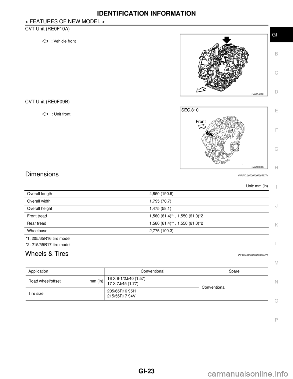
P CVT Unit (RE0F10A)
CVT Unit (RE0F09B)
DimensionsINFOID:0000000003852774
Unit: mm (in)
*1: 205/65R16 tire model
*2: 215/55R17 tire model
Wheels & TiresINFOID:0000000003852775
: Vehicle front
SAIA1496E
: Unit front
SAIA0360E
Overall length 4,850 (190.9)
Overall width 1,795 (70.7)
Overall height 1,475 (58.1)
Front tread 1,560 (61.4)*1, 1,550 (61.0)*2
Rear tread 1,560 (61.4)*1, 1,550 (61.0)*2
Wheelbase 2,775 (109.3)
Application Conventional Spare
Road wheel/offset mm (in)16 X 6-1/2J/40 (1.57)
17 X 7J/45 (1.77)
Conventional
Tire size205/65R16 95H
215/55R17 94V
Page 2517 of 5121
GI-24
< PRECAUTION >
PRECAUTIONS
PRECAUTION
PRECAUTIONS
DescriptionINFOID:0000000003852776
Observe the following precautions to ensure safe and proper servicing. These precautions are not
described in each individual section.
Precaution for Supplemental Restraint System (SRS) "AIR BAG" and "SEAT BELT
PRE-TENSIONER"
INFOID:0000000003852830
The Supplemental Restraint System such as “AIR BAG” and “SEAT BELT PRE-TENSIONER”, used along
with a front seat belt, helps to reduce the risk or severity of injury to the driver and front passenger for certain
types of collision. Information necessary to service the system safely is included in the “SRS AIRBAG” and
“SEAT BELT” of this Service Manual.
WARNING:
To avoid rendering the SRS inoperative, which could increase the risk of personal injury or death in
the event of a collision which would result in air bag inflation, all maintenance must be performed by
an authorized NISSAN/INFINITI dealer.
Improper maintenance, including incorrect removal and installation of the SRS, can lead to personal
injury caused by unintentional activation of the system. For removal of Spiral Cable and Air Bag
Module, see the “SRS AIRBAG”.
Never use electrical test equipment on any circuit related to the SRS unless instructed to in this Ser-
vice Manual. SRS wiring harnesses can be identified by yellow and/or orange harnesses or harness
connectors.
Precautions For Xenon Headlamp ServiceINFOID:0000000003852778
WARNING:
Comply with the following warnings to prevent any serious accident.
Disconnect the battery cable (negative terminal) or the power supply fuse before installing, remov-
ing, or touching the xenon headlamp (bulb included). The xenon headlamp contains high-voltage
generated parts.
Never work with wet hands.
Check the xenon headlamp ON-OFF status after assembling it to the vehicle. Never turn the xenon
headlamp ON in other conditions. Connect the power supply to the vehicle-side connector.
(Turning it ON outside the lamp case may cause fire or visual impairments.)
Never touch the bulb glass immediately after turning it OFF. It is extremely hot.
CAUTION:
Comply with the following cautions to prevent any error and malfunction.
Install the xenon bulb securely. (Insufficient bulb socket installation may melt the bulb, the connec-
tor, the housing, etc. by high-voltage leakage or corona discharge.)
Never perform HID circuit inspection with a tester.
Never touch the xenon bulb glass with hands. Never put oil and grease on it.
Dispose of the used xenon bulb after packing it in thick vinyl without breaking it.
Never wipe out dirt and contamination with organic solvent (thinner, gasoline, etc.).
Precaution Necessary for Steering Wheel Rotation after Battery Disconnect
INFOID:0000000003852856
NOTE:
Before removing and installing any control units, first turn the push-button ignition switch to the LOCK posi-
tion, then disconnect both battery cables.
After finishing work, confirm that all control unit connectors are connected properly, then re-connect both
battery cables.
Always use CONSULT-III to perform self-diagnosis as a part of each function inspection after finishing work.
If a DTC is detected, perform trouble diagnosis according to self-diagnosis results.
This vehicle is equipped with a push-button ignition switch and a steering lock unit.
If the battery is disconnected or discharged, the steering wheel will lock and cannot be turned.