2008 NISSAN TEANA engine
[x] Cancel search: enginePage 1089 of 5121
![NISSAN TEANA 2008 Service Manual BRC-148
< SYMPTOM DIAGNOSIS >[VDC/TCS/ABS]
NORMAL OPERATING CONDITION
NORMAL OPERATING CONDITION
DescriptionINFOID:0000000003767029
Symptom Result
Slight vibrations are felt on the brake pedal and the NISSAN TEANA 2008 Service Manual BRC-148
< SYMPTOM DIAGNOSIS >[VDC/TCS/ABS]
NORMAL OPERATING CONDITION
NORMAL OPERATING CONDITION
DescriptionINFOID:0000000003767029
Symptom Result
Slight vibrations are felt on the brake pedal and the](/manual-img/5/57391/w960_57391-1088.png)
BRC-148
< SYMPTOM DIAGNOSIS >[VDC/TCS/ABS]
NORMAL OPERATING CONDITION
NORMAL OPERATING CONDITION
DescriptionINFOID:0000000003767029
Symptom Result
Slight vibrations are felt on the brake pedal and the operation noises occur, when VDC, TCS or ABS is acti-
vated.
This is a normal condi-
tion due to the VDC,
TCS or ABS activation. Stopping distance is longer than that of vehicles without ABS when the vehicle drives on rough, gravel, or
snow-covered (fresh, deep snow) roads.
The brake pedal moves and generates noises, when TCS or VDC is activated due to rapid acceleration or
sharp turn.
The brake pedal vibrates and motor operation noises occur from the engine room, after the engine starts and
just after the vehicle starts.This is a normal, and it is
caused by the ABS op-
eration check.
Depending on the road conditions, the driver may experience a sluggish feel. This is normal, because
TCS places the highest
priority on the optimum
traction (stability). TCS may activate momentarily if wheel speed changes when driving over location where friction coefficient
varies, when downshifting, or when fully depressing accelerator pedal.
The ABS warning lamp, VDC OFF indicator lamp and SLIP indicator lamp may turn ON when the vehicle is
subject to strong shaking or large vibration, such as when the vehicle is rotating on a turntable or located on
a ship while the engine is running. In this case, restart the
engine on a normal
road. If the normal con-
dition is restored, there
is no malfunction. At
that time, erase the self-
diagnosis memory. VDC may not operate normally or the ABS warning lamp, VDC OFF indicator lamp, and SLIP indicator lamp
may illuminate, when running on a special road that is extremely slanted (e.g. bank in a circuit course).
A malfunction may occur in the yaw rate/side G sensor system, when the vehicle turns sharply, such as dur-
ing a spin turn, axle turn, or drift driving, while the VDC function is off (VDC OFF indicator lamp illuminated).
The vehicle speed will not increase even though the accelerator pedal is depressed, when inspecting the
speedometer on a 2-wheel chassis dynamometer. Normal (Deactivate the
VDC/TCS function be-
fore performing an in-
spection on a chassis
dynamometer.)
VDC OFF indicator lamp and SLIP indicator lamp may simultaneously turn on when low tire pressure warn-
ing lamp turns on.This is not a VDC sys-
tem error but results
from characteristic
change of tire.
Page 1091 of 5121
![NISSAN TEANA 2008 Service Manual BRC-150
< PRECAUTION >[VDC/TCS/ABS]
PRECAUTIONS
Precaution for Brake Control
INFOID:0000000003767032
When starting engine or when starting vehicle just after starting engine, brake pedal may vibrate NISSAN TEANA 2008 Service Manual BRC-150
< PRECAUTION >[VDC/TCS/ABS]
PRECAUTIONS
Precaution for Brake Control
INFOID:0000000003767032
When starting engine or when starting vehicle just after starting engine, brake pedal may vibrate](/manual-img/5/57391/w960_57391-1090.png)
BRC-150
< PRECAUTION >[VDC/TCS/ABS]
PRECAUTIONS
Precaution for Brake Control
INFOID:0000000003767032
When starting engine or when starting vehicle just after starting engine, brake pedal may vibrate or motor
operating noise may be heard from engine compartment. This is normal condition.
When an error is indicated by ABS or another warning lamp, collect all necessary information from customer
(what symptoms are present under what conditions) and check for estimate causes before starting diagnos-
tic servicing. Besides electrical system inspection, check brake booster operation, brake fluid level, and oil
leaks.
If tire size and type are used in an improper combination, or brake pads are not Genuine NISSAN parts,
stopping distance or steering stability may deteriorate.
ABS might be out of order or malfunctions by putting a radio (wiring inclusive), an antenna and a lead-in wire
near the control unit.
If aftermarket parts (car stereo, CD player, etc.) have been installed, check for incidents such as harness
pinches, open circuits, and improper wiring.
VDC system may not operate normally or a VDC OFF indicator lamp or SLIP indicator lamp may light.
- When replacing the following parts with parts other than genuine parts or making modifications: Suspension
related parts (shock absorber, spring, bushing, etc.), tires, wheels (other than specified sizes), brake-related
parts (pad, rotor, caliper, etc.), engine-related parts (muffler, ECM, etc.) and body reinforcement-related parts
(roll bar, tower bar, etc.).
- When driving with worn or deteriorated suspension, tires and brake-related parts.
Precautions for Harness RepairINFOID:0000000003843440
COMMUNICATION LINE
Solder the repaired area and wrap tape around the soldered area.
NOTE:
A fray of twisted lines must be within 110 mm (4.33 in).
Bypass connection is never allowed at the repaired area.
NOTE:
Bypass connection may cause communication error as spliced
wires that are separate from the main line or twisted lines lose
noise immunity.
Replace the applicable harness as an assembly if error is detected
on the shield lines of communication line.
SKIB8766E
SKIB8767E
Page 1101 of 5121
CHG
DIAGNOSIS AND REPAIR WORKFLOW
CHG-3
< BASIC INSPECTION >
C
D
E
F
G
H
I
J
K
L B A
O
P N
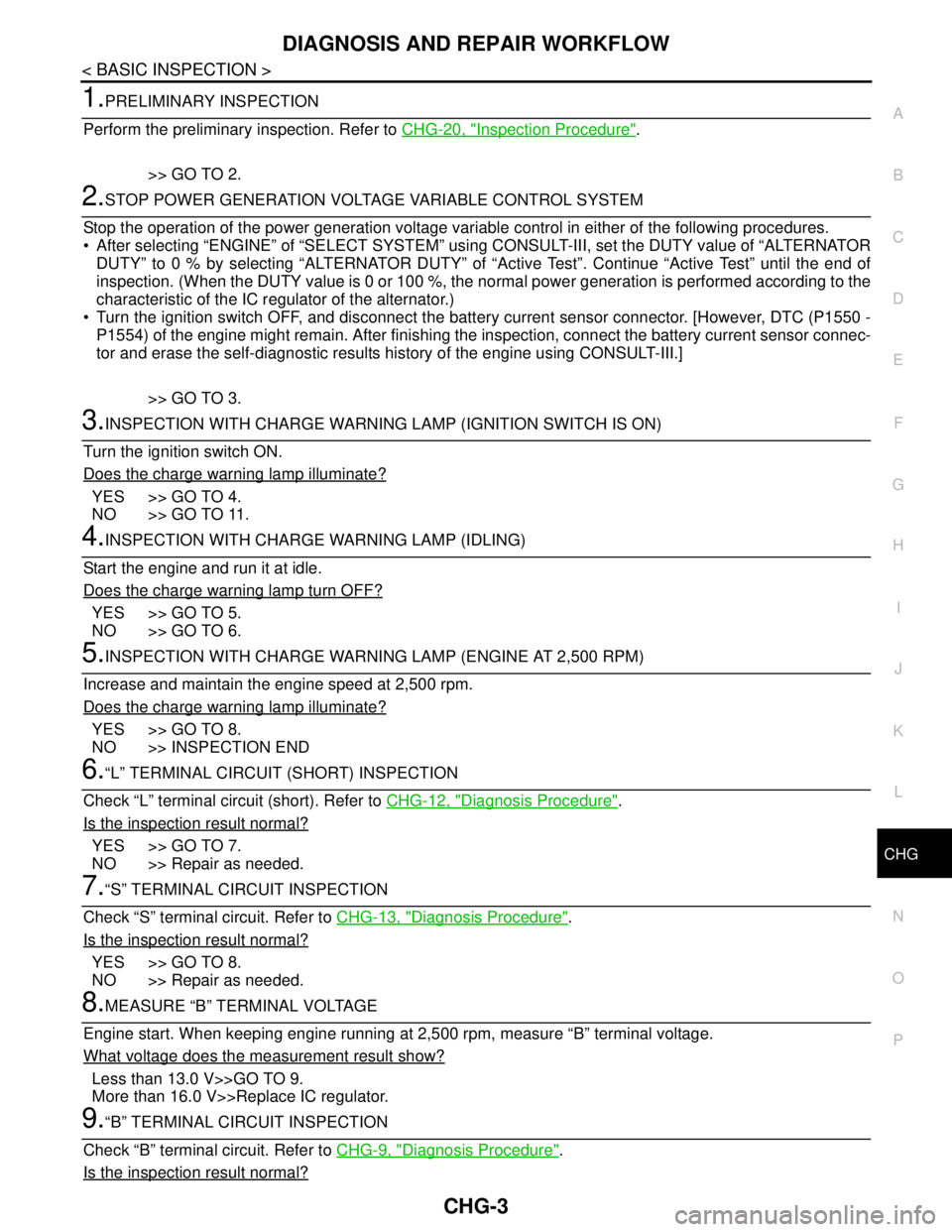
1.PRELIMINARY INSPECTION
Perform the preliminary inspection. Refer to CHG-20, "
Inspection Procedure".
>> GO TO 2.
2.STOP POWER GENERATION VOLTAGE VARIABLE CONTROL SYSTEM
Stop the operation of the power generation voltage variable control in either of the following procedures.
• After selecting “ENGINE” of “SELECT SYSTEM” using CONSULT-III, set the DUTY value of “ALTERNATOR
DUTY” to 0 % by selecting “ALTERNATOR DUTY” of “Active Test”. Continue “Active Test” until the end of
inspection. (When the DUTY value is 0 or 100 %, the normal power generation is performed according to the
characteristic of the IC regulator of the alternator.)
Turn the ignition switch OFF, and disconnect the battery current sensor connector. [However, DTC (P1550 -
P1554) of the engine might remain. After finishing the inspection, connect the battery current sensor connec-
tor and erase the self-diagnostic results history of the engine using CONSULT-III.]
>> GO TO 3.
3.INSPECTION WITH CHARGE WARNING LAMP (IGNITION SWITCH IS ON)
Turn the ignition switch ON.
Does the charge warning lamp illuminate?
YES >> GO TO 4.
NO >> GO TO 11.
4.INSPECTION WITH CHARGE WARNING LAMP (IDLING)
Start the engine and run it at idle.
Does the charge warning lamp turn OFF?
YES >> GO TO 5.
NO >> GO TO 6.
5.INSPECTION WITH CHARGE WARNING LAMP (ENGINE AT 2,500 RPM)
Increase and maintain the engine speed at 2,500 rpm.
Does the charge warning lamp illuminate?
YES >> GO TO 8.
NO >> INSPECTION END
6.“L” TERMINAL CIRCUIT (SHORT) INSPECTION
Check “L” terminal circuit (short). Refer to CHG-12, "
Diagnosis Procedure".
Is the inspection result normal?
YES >> GO TO 7.
NO >> Repair as needed.
7.“S” TERMINAL CIRCUIT INSPECTION
Check “S” terminal circuit. Refer to CHG-13, "
Diagnosis Procedure".
Is the inspection result normal?
YES >> GO TO 8.
NO >> Repair as needed.
8.MEASURE “B” TERMINAL VOLTAGE
Engine start. When keeping engine running at 2,500 rpm, measure “B” terminal voltage.
What voltage does the measurement result show?
Less than 13.0 V>>GO TO 9.
More than 16.0 V>>Replace IC regulator.
9.“B” TERMINAL CIRCUIT INSPECTION
Check “B” terminal circuit. Refer to CHG-9, "
Diagnosis Procedure".
Is the inspection result normal?
Page 1105 of 5121
CHG
POWER GENERATION VOLTAGE VARIABLE CONTROL SYSTEM
CHG-7
< FUNCTION DIAGNOSIS >
C
D
E
F
G
H
I
J
K
L B A
O
P N
POWER GENERATION VOLTAGE VARIABLE CONTROL SYSTEM
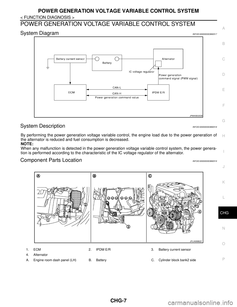
System DiagramINFOID:0000000003860517
System DescriptionINFOID:0000000003860518
By performing the power generation voltage variable control, the engine load due to the power generation of
the alternator is reduced and fuel consumption is decreased.
NOTE:
When any malfunction is detected in the power generation voltage variable control system, the power genera-
tion is performed according to the characteristic of the IC voltage regulator of the alternator.
Component Parts LocationINFOID:0000000003860519
JPMIA0632GB
1. ECM 2. IPDM E/R 3. Battery current sensor
4. Alternator
A. Engine room dash panel (LH) B. Battery C. Cylinder block bank2 side
JPLIA0888ZZ
Page 1107 of 5121
CHG
B TERMINAL CIRCUIT
CHG-9
< COMPONENT DIAGNOSIS >
C
D
E
F
G
H
I
J
K
L B A
O
P N
COMPONENT DIAGNOSIS
B TERMINAL CIRCUIT
DescriptionINFOID:0000000003860521
“B” terminal circuit supplies power to charge the battery and to operate the vehicle’s electrical system.
Diagnosis ProcedureINFOID:0000000003860522
1.CHECK “B” TERMINAL CONNECTION
1. Turn ignition switch OFF.
2. Check if “B” terminal is clean and tight.
Is the inspection result normal?
YES >> GO TO 2.
NO >> Repair “B” terminal connection. Confirm repair by performing complete Starting/Charging system
test. Refer to Technical Service Bulletin.
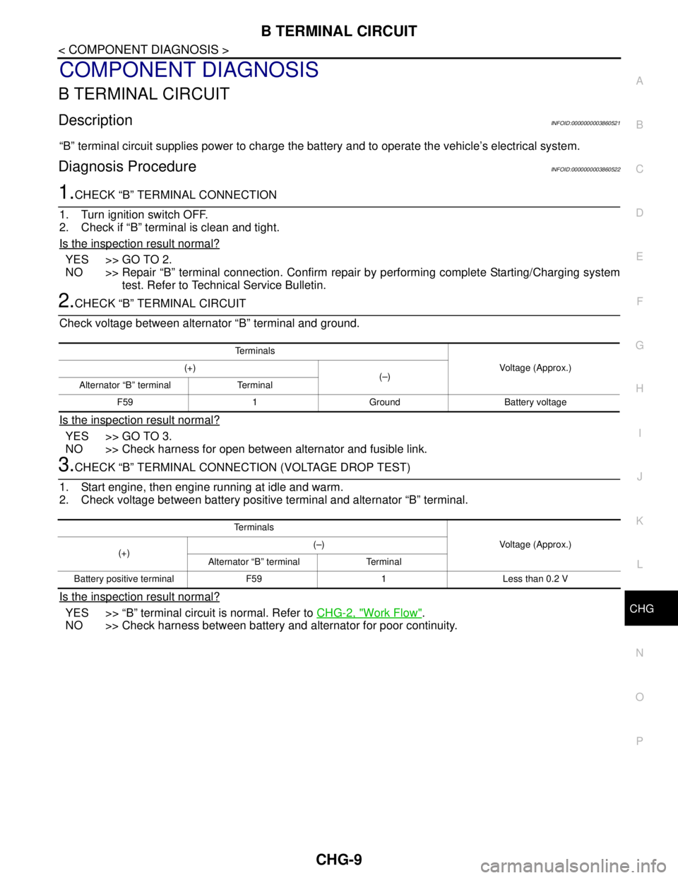
2.CHECK “B” TERMINAL CIRCUIT
Check voltage between alternator “B” terminal and ground.
Is the inspection result normal?
YES >> GO TO 3.
NO >> Check harness for open between alternator and fusible link.
3.CHECK “B” TERMINAL CONNECTION (VOLTAGE DROP TEST)
1. Start engine, then engine running at idle and warm.
2. Check voltage between battery positive terminal and alternator “B” terminal.
Is the inspection result normal?
YES >> “B” terminal circuit is normal. Refer to CHG-2, "Work Flow".
NO >> Check harness between battery and alternator for poor continuity.
Te r m i n a l s
Voltage (Approx.) (+)
(–)
Alternator “B” terminal Terminal
F59 1 Ground Battery voltage
Te r m i n a l s
Voltage (Approx.)
(+)(–)
Alternator “B” terminal Terminal
Battery positive terminal F59 1 Less than 0.2 V
Page 1108 of 5121
CHG-10
< COMPONENT DIAGNOSIS >
L TERMINAL CIRCUIT (OPEN)
L TERMINAL CIRCUIT (OPEN)
DescriptionINFOID:0000000003860523
The “L” terminal circuit controls the charge warning lamp. The charge warning lamp illuminates when the igni-
tion switch is set to ON or START. When the alternator is providing sufficient voltage with the engine running,
the charge warning lamp will go off. If the charge warning lamp illuminates with the engine running, a malfunc-
tion is indicated.
Diagnosis ProcedureINFOID:0000000003860524
1.CHECK “L” TERMINAL CONNECTION
1. Turn ignition switch OFF.
2. Check if “L” terminal is clean and tight.
Is the inspection result normal?
YES >> GO TO 2.
NO >> Repair “L” terminal connection. Confirm repair by performing complete Starting/Charging system
test. Refer to Technical Service Bulletin.
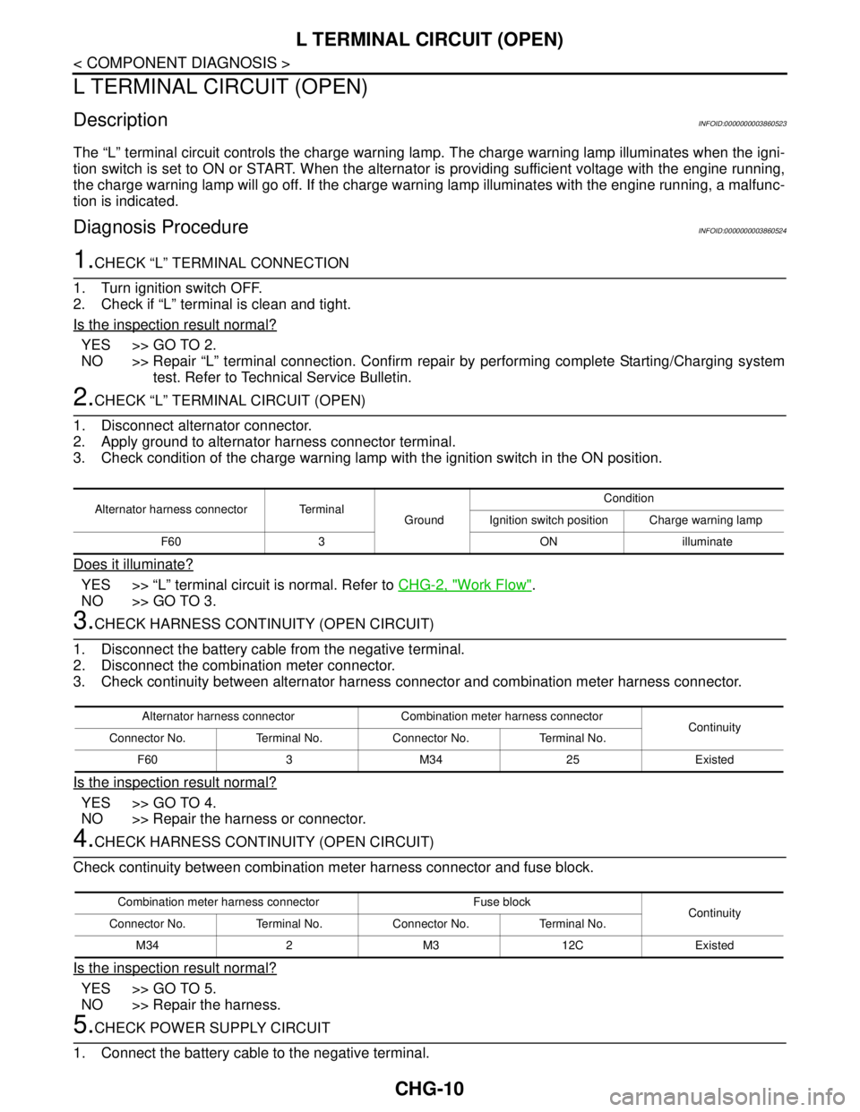
2.CHECK “L” TERMINAL CIRCUIT (OPEN)
1. Disconnect alternator connector.
2. Apply ground to alternator harness connector terminal.
3. Check condition of the charge warning lamp with the ignition switch in the ON position.
Does it illuminate?
YES >> “L” terminal circuit is normal. Refer to CHG-2, "Work Flow".
NO >> GO TO 3.
3.CHECK HARNESS CONTINUITY (OPEN CIRCUIT)
1. Disconnect the battery cable from the negative terminal.
2. Disconnect the combination meter connector.
3. Check continuity between alternator harness connector and combination meter harness connector.
Is the inspection result normal?
YES >> GO TO 4.
NO >> Repair the harness or connector.
4.CHECK HARNESS CONTINUITY (OPEN CIRCUIT)
Check continuity between combination meter harness connector and fuse block.
Is the inspection result normal?
YES >> GO TO 5.
NO >> Repair the harness.
5.CHECK POWER SUPPLY CIRCUIT
1. Connect the battery cable to the negative terminal.
Alternator harness connector Terminal
GroundCondition
Ignition switch position Charge warning lamp
F60 3 ON illuminate
Alternator harness connector Combination meter harness connector
Continuity
Connector No. Terminal No. Connector No. Terminal No.
F60 3 M34 25 Existed
Combination meter harness connector Fuse block
Continuity
Connector No. Terminal No. Connector No. Terminal No.
M34 2 M3 12C Existed
Page 1110 of 5121

CHG-12
< COMPONENT DIAGNOSIS >
L TERMINAL CIRCUIT (SHORT)
L TERMINAL CIRCUIT (SHORT)
DescriptionINFOID:0000000003860525
The “L” terminal circuit controls the charge warning lamp. The charge warning lamp illuminates when the igni-
tion switch is set to ON or START. When the alternator is providing sufficient voltage with the engine running,
the charge warning lamp will go off. If the charge warning lamp illuminates with the engine running, a malfunc-
tion is indicated.
Diagnosis ProcedureINFOID:0000000003860526
1.CHECK “L” TERMINAL CIRCUIT (SHORT)
1. Turn ignition switch OFF.
2. Disconnect alternator connector.
3. Turn ignition switch ON.
Does charge warning lamp illuminate?
YES >> GO TO 2.
NO >> Refer to CHG-2, "
Work Flow".
2.CHECK HARNESS CONTINUITY (SHORT CIRCUIT)
1. Turn the ignition switch OFF.
2. Disconnect the battery cable from the negative terminal.
3. Disconnect combination meter connector.
4. Check continuity between combination meter harness connector and ground.
Is the inspection result normal?
YES >> Replace combination meter.
NO >> Repair the harness.
Combination meter harness connector
GroundContinuity
Connector No. Terminal No.
M34 25 Not existed
Page 1115 of 5121
CHG
CHARGING SYSTEM
CHG-17
< SYMPTOM DIAGNOSIS >
C
D
E
F
G
H
I
J
K
L B A
O
P N
SYMPTOM DIAGNOSIS
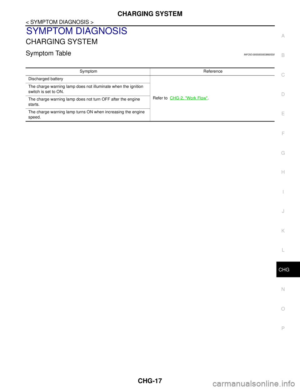
CHARGING SYSTEM
Symptom TableINFOID:0000000003860530
Symptom Reference
Discharged battery
Refer to CHG-2, "
Work Flow". The charge warning lamp does not illuminate when the ignition
switch is set to ON.
The charge warning lamp does not turn OFF after the engine
starts.
The charge warning lamp turns ON when increasing the engine
speed.