2008 NISSAN TEANA engine
[x] Cancel search: enginePage 1133 of 5121
CO-10
< ON-VEHICLE MAINTENANCE >
ENGINE COOLANT
6. Install air duct assembly and air cleaner cases (upper and lower) assembly. Refer to EM-26, "Exploded
View".
7. Install radiator cap.
8. Warm up engine until opening thermostat. Standard for warming-up time is approximately 10 minutes at
3,000 rpm.
Check thermostat opening condition by touching radiator hose (lower) to see a flow of warm water.
CAUTION:
Watch water temperature gauge so as not to overheat engine.
9. Stop the engine and cool down to less than approximately 50°C (122°F).
Cool down using fan to reduce the time.
If necessary, refill radiator up to filler neck with engine coolant.
CAUTION:
Never adhere the engine coolant to electronic equipments. (alternator etc.)
10. Refill reservoir tank to “MAX” level line with engine coolant.
11. Repeat steps 7 through 10 two or more times with radiator cap installed until engine coolant level no
longer drops.
12. Check cooling system for leakage with engine running.
13. Warm up the engine, and check for sound of engine coolant flow while running engine from idle up to
3,000 rpm with heater temperature controller set at several position between “COOL” and “WARM”.
Sound may be noticeable at heater unit.
14. Repeat step 13 three times.
15. If sound is heard, bleed air from cooling system by repeating step 5, and steps from 7 to 14 until engine
coolant level no longer drops.
FlushingINFOID:0000000003793169
1. Install reservoir tank if removed, and radiator drain plug.
CAUTION:
Be sure to clean drain plug and install with new O-ring.
If water drain plugs on cylinder block are removed, close and tighten them. Refer to EM-110, "
Dis-
assembly and Assembly".
2. Remove air duct assembly and air cleaner cases (upper and lower) assembly. Refer to EM-26, "
Exploded
View".
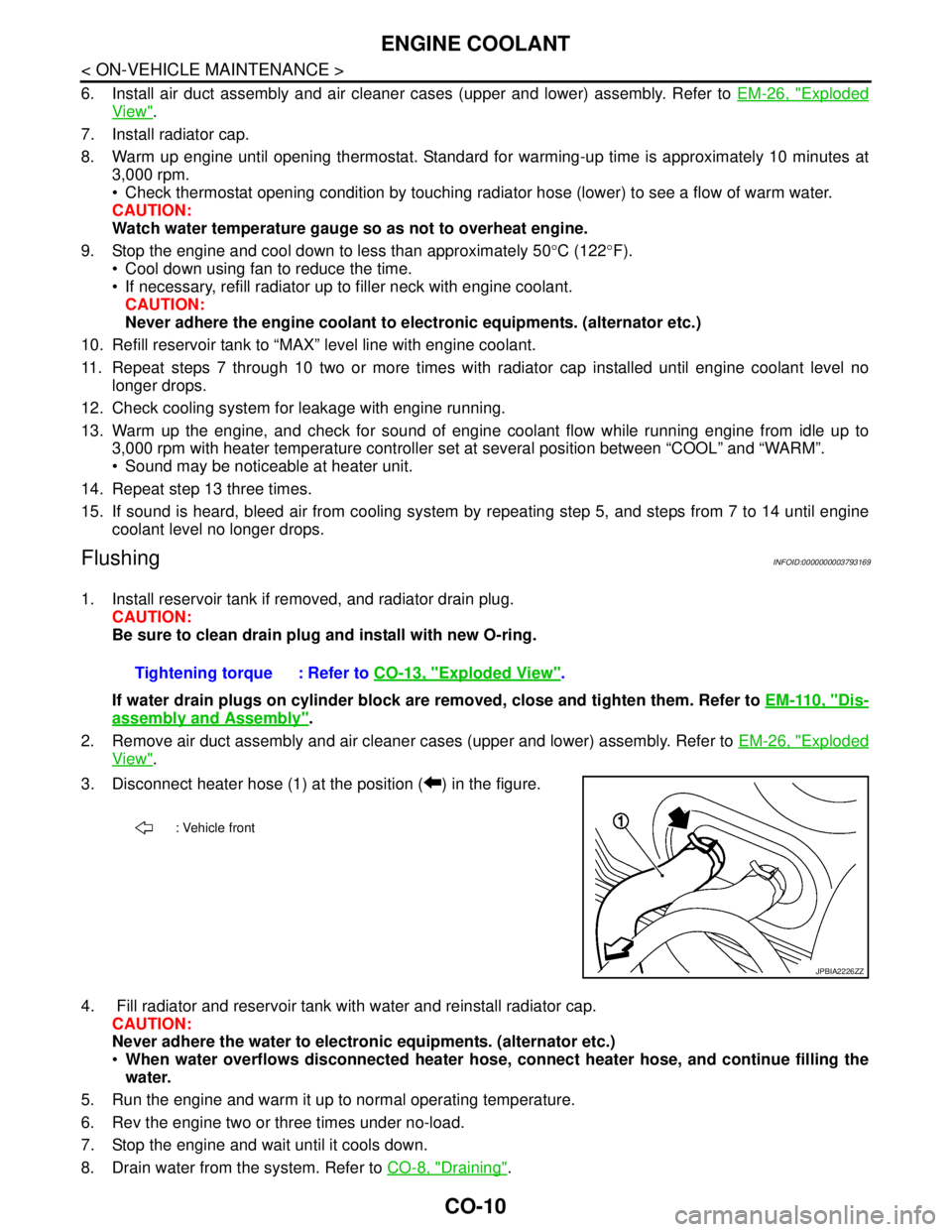
3. Disconnect heater hose (1) at the position ( ) in the figure.
4. Fill radiator and reservoir tank with water and reinstall radiator cap.
CAUTION:
Never adhere the water to electronic equipments. (alternator etc.)
When water overflows disconnected heater hose, connect heater hose, and continue filling the
water.
5. Run the engine and warm it up to normal operating temperature.
6. Rev the engine two or three times under no-load.
7. Stop the engine and wait until it cools down.
8. Drain water from the system. Refer to CO-8, "
Draining". Tightening torque : Refer to CO-13, "
Exploded View".
: Vehicle front
JPBIA2226ZZ
Page 1134 of 5121
ENGINE COOLANT
CO-11
< ON-VEHICLE MAINTENANCE >
C
D
E
F
G
H
I
J
K
L
MA
CO
N
P O
9. Repeat steps 1 through 8 until clear water begins to drain from radiator.
Page 1135 of 5121
CO-12
< ON-VEHICLE MAINTENANCE >
RADIATOR
RADIATOR
RADIATOR CAP
RADIATOR CAP : InspectionINFOID:0000000003793170
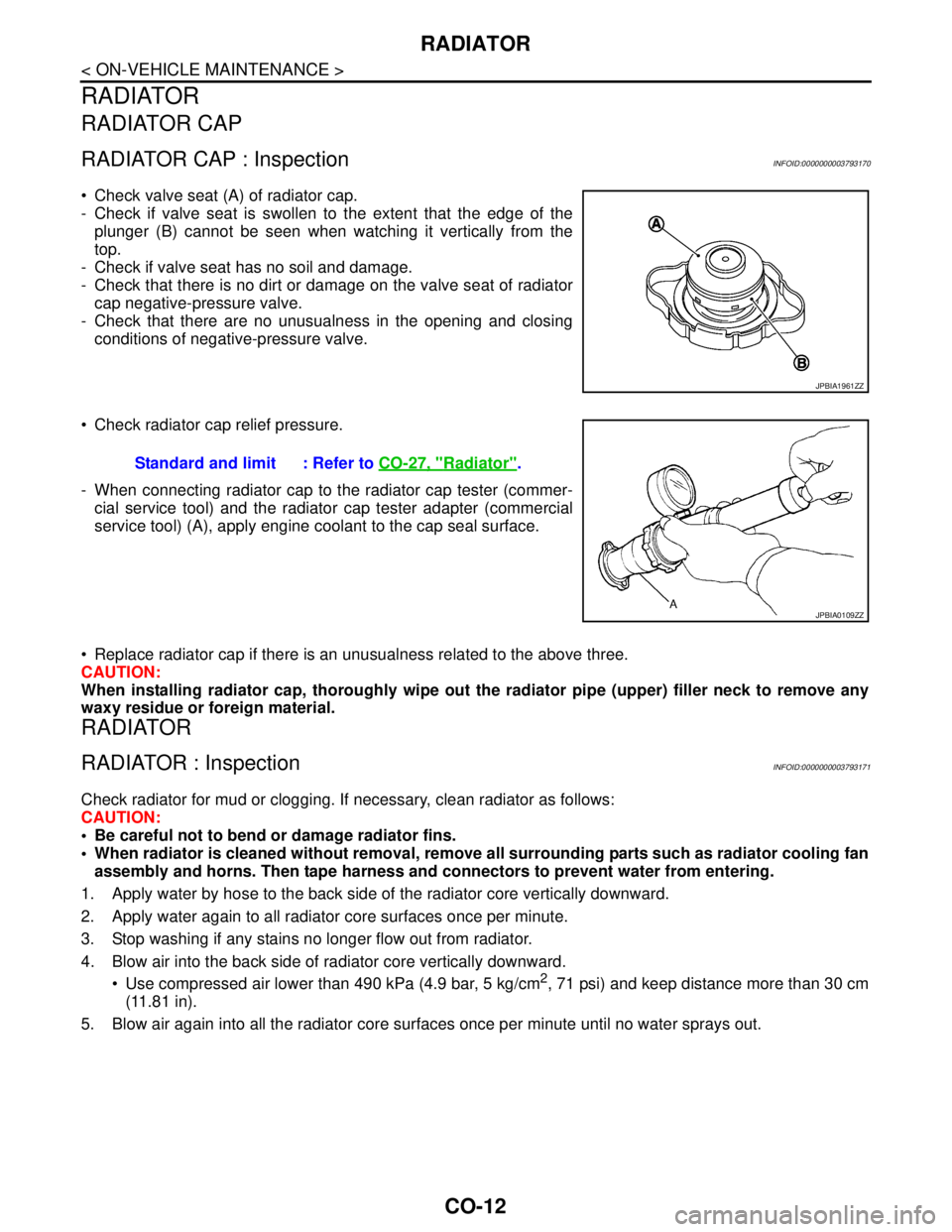
Check valve seat (A) of radiator cap.
- Check if valve seat is swollen to the extent that the edge of the
plunger (B) cannot be seen when watching it vertically from the
top.
- Check if valve seat has no soil and damage.
- Check that there is no dirt or damage on the valve seat of radiator
cap negative-pressure valve.
- Check that there are no unusualness in the opening and closing
conditions of negative-pressure valve.
Check radiator cap relief pressure.
- When connecting radiator cap to the radiator cap tester (commer-
cial service tool) and the radiator cap tester adapter (commercial
service tool) (A), apply engine coolant to the cap seal surface.
Replace radiator cap if there is an unusualness related to the above three.
CAUTION:
When installing radiator cap, thoroughly wipe out the radiator pipe (upper) filler neck to remove any
waxy residue or foreign material.
RADIATOR
RADIATOR : InspectionINFOID:0000000003793171
Check radiator for mud or clogging. If necessary, clean radiator as follows:
CAUTION:
Be careful not to bend or damage radiator fins.
When radiator is cleaned without removal, remove all surrounding parts such as radiator cooling fan
assembly and horns. Then tape harness and connectors to prevent water from entering.
1. Apply water by hose to the back side of the radiator core vertically downward.
2. Apply water again to all radiator core surfaces once per minute.
3. Stop washing if any stains no longer flow out from radiator.
4. Blow air into the back side of radiator core vertically downward.
Use compressed air lower than 490 kPa (4.9 bar, 5 kg/cm
2, 71 psi) and keep distance more than 30 cm
(11.81 in).
5. Blow air again into all the radiator core surfaces once per minute until no water sprays out.
JPBIA1961ZZ
Standard and limit : Refer to CO-27, "Radiator".
JPBIA0109ZZ
Page 1137 of 5121
CO-14
< ON-VEHICLE REPAIR >
RADIATOR
WARNING:
Never remove radiator cap when engine is hot. Serious burns could occur from high-pressure engine
coolant escaping from radiator. Wrap a thick cloth around the cap. Slowly turn it a quarter of a turn to
release built-up pressure. Carefully remove radiator cap by turning it all the way.
1. Remove the following parts:
Engine under cover.
Air duct (inlet): Refer to EM-26, "
Exploded View".
Horn: Refer to HRN-6, "
Exploded View".
Hood lock: Refer to DLK-220, "
Exploded View".
2. Drain engine coolant from radiator. Refer to CO-8, "
Draining".
CAUTION:
Perform this step when the engine is cold.
Never spill engine coolant on drive belt.
3. Disconnect reservoir tank hose from radiator pipe (upper).
4. Disconnect CVT fluid cooler hoses from radiator.
Install blind plug to avoid leakage of CVT fluid.
5. Disconnect Low-pressure flexible hose from lower pressure pipe, and then move it to aside. Refer to HA-
38, "Exploded View".
6. Remove radiator cap adapter and radiator hoses (upper) and radiator pipe (upper) assembly.
CAUTION:
Be careful not to allow engine coolant to contact drive belt.
7. Disconnect radiator hose (lower) from radiator.
8. Remove condenser. Refer to HA-46, "
Exploded View".
CAUTION:
Be careful not to damage condenser core.
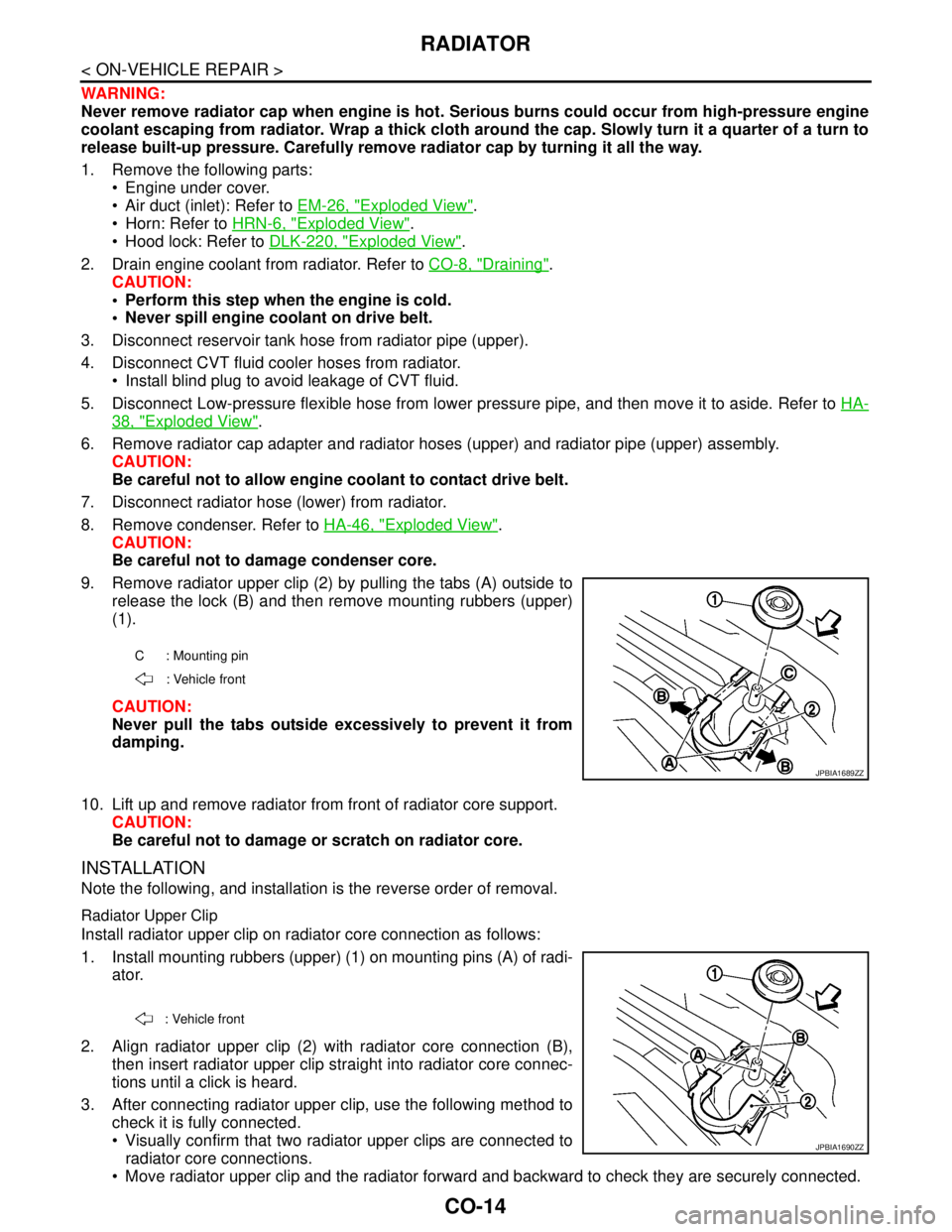
9. Remove radiator upper clip (2) by pulling the tabs (A) outside to
release the lock (B) and then remove mounting rubbers (upper)
(1).
CAUTION:
Never pull the tabs outside excessively to prevent it from
damping.
10. Lift up and remove radiator from front of radiator core support.
CAUTION:
Be careful not to damage or scratch on radiator core.
INSTALLATION
Note the following, and installation is the reverse order of removal.
Radiator Upper Clip
Install radiator upper clip on radiator core connection as follows:
1. Install mounting rubbers (upper) (1) on mounting pins (A) of radi-
ator.
2. Align radiator upper clip (2) with radiator core connection (B),
then insert radiator upper clip straight into radiator core connec-
tions until a click is heard.
3. After connecting radiator upper clip, use the following method to
check it is fully connected.
Visually confirm that two radiator upper clips are connected to
radiator core connections.
Move radiator upper clip and the radiator forward and backward to check they are securely connected.
C : Mounting pin
: Vehicle front
JPBIA1689ZZ
: Vehicle front
JPBIA1690ZZ
Page 1138 of 5121
RADIATOR
CO-15
< ON-VEHICLE REPAIR >
C
D
E
F
G
H
I
J
K
L
MA
CO
N
P O
InspectionINFOID:0000000003793174
INSPECTION AFTER INSTALLATION
Check for leakage of engine coolant using the radiator cap tester adapter (commercial service tool) and the
radiator cap tester (commercial service tool). Refer to CO-8, "
Inspection".
Start and warm up the engine. Visually check that there is no leakage of engine coolant and CVT fluid.
Page 1139 of 5121
CO-16
< ON-VEHICLE REPAIR >
COOLING FAN
COOLING FAN
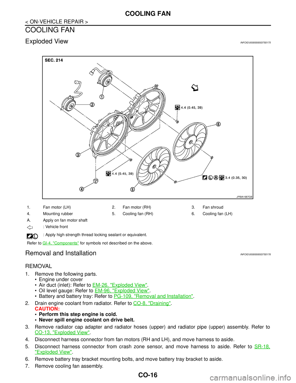
Exploded ViewINFOID:0000000003793175
Removal and InstallationINFOID:0000000003793176
REMOVAL
1. Remove the following parts.
Engine under cover
Air duct (inlet): Refer to EM-26, "
Exploded View".
Oil level gauge: Refer to EM-96, "
Exploded View".
Battery and battery tray: Refer to PG-109, "
Removal and Installation".
2. Drain engine coolant from radiator. Refer to CO-8, "
Draining".
CAUTION:
Perform this step engine is cold.
Never spill engine coolant on drive belt.
3. Remove radiator cap adapter and radiator hoses (upper) and radiator pipe (upper) assembly. Refer to
CO-13, "
Exploded View".
4. Disconnect harness connector from fan motors (RH and LH), and move harness to aside.
5. Disconnect harness connector from crash zone sensor, and move harness to aside. Refer to SR-18,
"Exploded View".
6. Remove battery tray bracket mounting bolts, and move battery tray bracket to aside.
7. Remove cooling fan assembly.
1. Fan motor (LH) 2. Fan motor (RH) 3. Fan shroud
4. Mounting rubber 5. Cooling fan (RH) 6. Cooling fan (LH)
A. Apply on fan motor shaft
: Vehicle front
: Apply high strength thread locking sealant or equivalent.
Refer to GI-4, "
Components" for symbols not described on the above.
JPBIA1687GB
Page 1141 of 5121
CO-18
< ON-VEHICLE REPAIR >
WATER PUMP
WATER PUMP
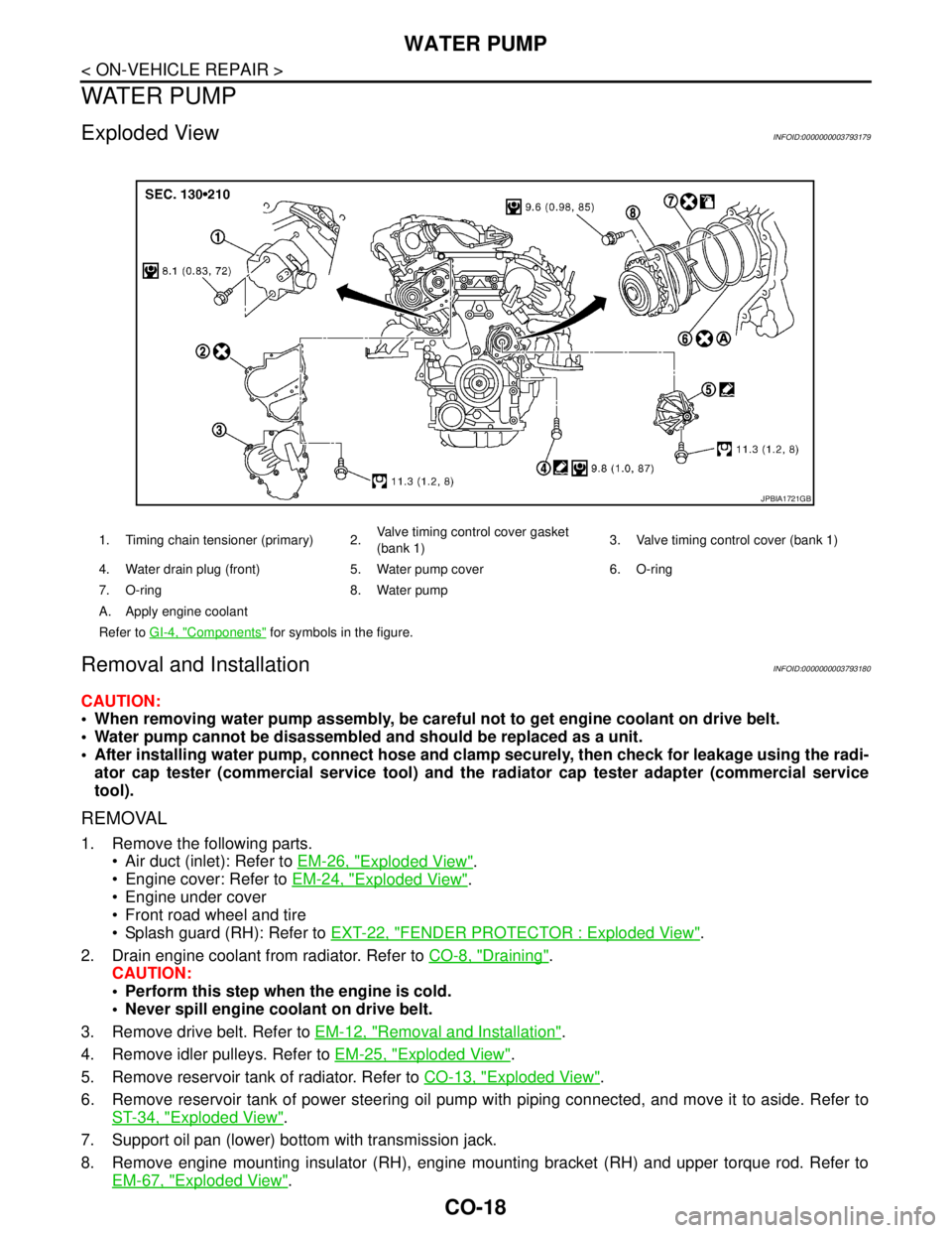
Exploded ViewINFOID:0000000003793179
Removal and InstallationINFOID:0000000003793180
CAUTION:
When removing water pump assembly, be careful not to get engine coolant on drive belt.
Water pump cannot be disassembled and should be replaced as a unit.
After installing water pump, connect hose and clamp securely, then check for leakage using the radi-
ator cap tester (commercial service tool) and the radiator cap tester adapter (commercial service
tool).
REMOVAL
1. Remove the following parts.
Air duct (inlet): Refer to EM-26, "
Exploded View".
Engine cover: Refer to EM-24, "
Exploded View".
Engine under cover
Front road wheel and tire
Splash guard (RH): Refer to EXT-22, "
FENDER PROTECTOR : Exploded View".
2. Drain engine coolant from radiator. Refer to CO-8, "
Draining".
CAUTION:
Perform this step when the engine is cold.
Never spill engine coolant on drive belt.
3. Remove drive belt. Refer to EM-12, "
Removal and Installation".
4. Remove idler pulleys. Refer to EM-25, "
Exploded View".
5. Remove reservoir tank of radiator. Refer to CO-13, "
Exploded View".
6. Remove reservoir tank of power steering oil pump with piping connected, and move it to aside. Refer to
ST-34, "
Exploded View".
7. Support oil pan (lower) bottom with transmission jack.
8. Remove engine mounting insulator (RH), engine mounting bracket (RH) and upper torque rod. Refer to
EM-67, "
Exploded View".
1. Timing chain tensioner (primary) 2.Valve timing control cover gasket
(bank 1)3. Valve timing control cover (bank 1)
4. Water drain plug (front) 5. Water pump cover 6. O-ring
7. O-ring 8. Water pump
A. Apply engine coolant
Refer to GI-4, "
Components" for symbols in the figure.
JPBIA1721GB
Page 1142 of 5121
WATER PUMP
CO-19
< ON-VEHICLE REPAIR >
C
D
E
F
G
H
I
J
K
L
MA
CO
N
P O
9. Remove water drain plug (front) on water pump side of cylinder block to drain engine coolant from engine
inside.
10. Remove valve timing control cover (bank 1) and water pump cover from front timing chain case.
Use the seal cutter [SST: KV10111100 (J37228)] to cut liquid gasket for removal.
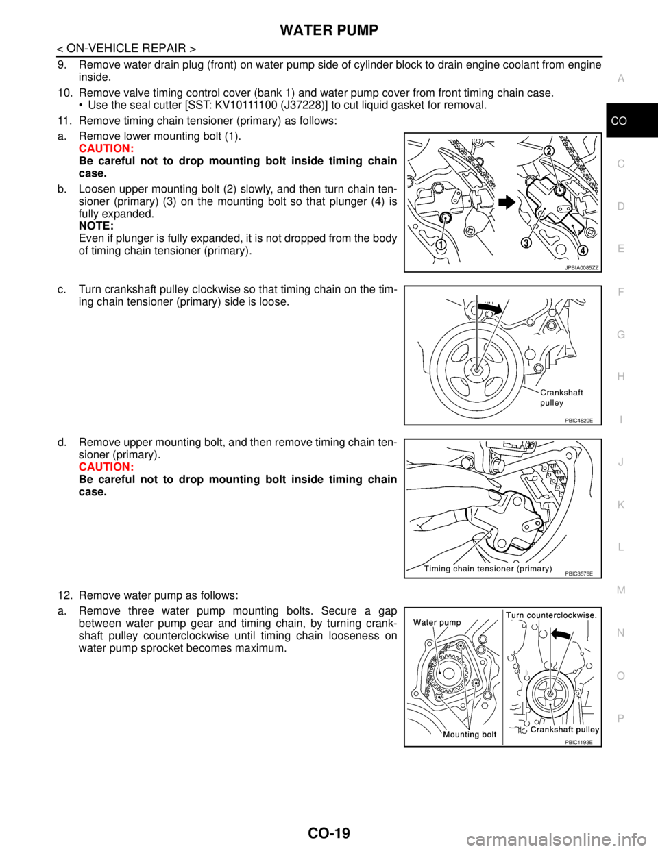
11. Remove timing chain tensioner (primary) as follows:
a. Remove lower mounting bolt (1).
CAUTION:
Be careful not to drop mounting bolt inside timing chain
case.
b. Loosen upper mounting bolt (2) slowly, and then turn chain ten-
sioner (primary) (3) on the mounting bolt so that plunger (4) is
fully expanded.
NOTE:
Even if plunger is fully expanded, it is not dropped from the body
of timing chain tensioner (primary).
c. Turn crankshaft pulley clockwise so that timing chain on the tim-
ing chain tensioner (primary) side is loose.
d. Remove upper mounting bolt, and then remove timing chain ten-
sioner (primary).
CAUTION:
Be careful not to drop mounting bolt inside timing chain
case.
12. Remove water pump as follows:
a. Remove three water pump mounting bolts. Secure a gap
between water pump gear and timing chain, by turning crank-
shaft pulley counterclockwise until timing chain looseness on
water pump sprocket becomes maximum.
JPBIA0085ZZ
PBIC4820E
PBIC3576E
PBIC1193E