2008 NISSAN TEANA check oil
[x] Cancel search: check oilPage 1992 of 5121
CYLINDER BLOCK
EM-117
< DISASSEMBLY AND ASSEMBLY >
C
D
E
F
G
H
I
J
K
L
MA
EM
N
P O
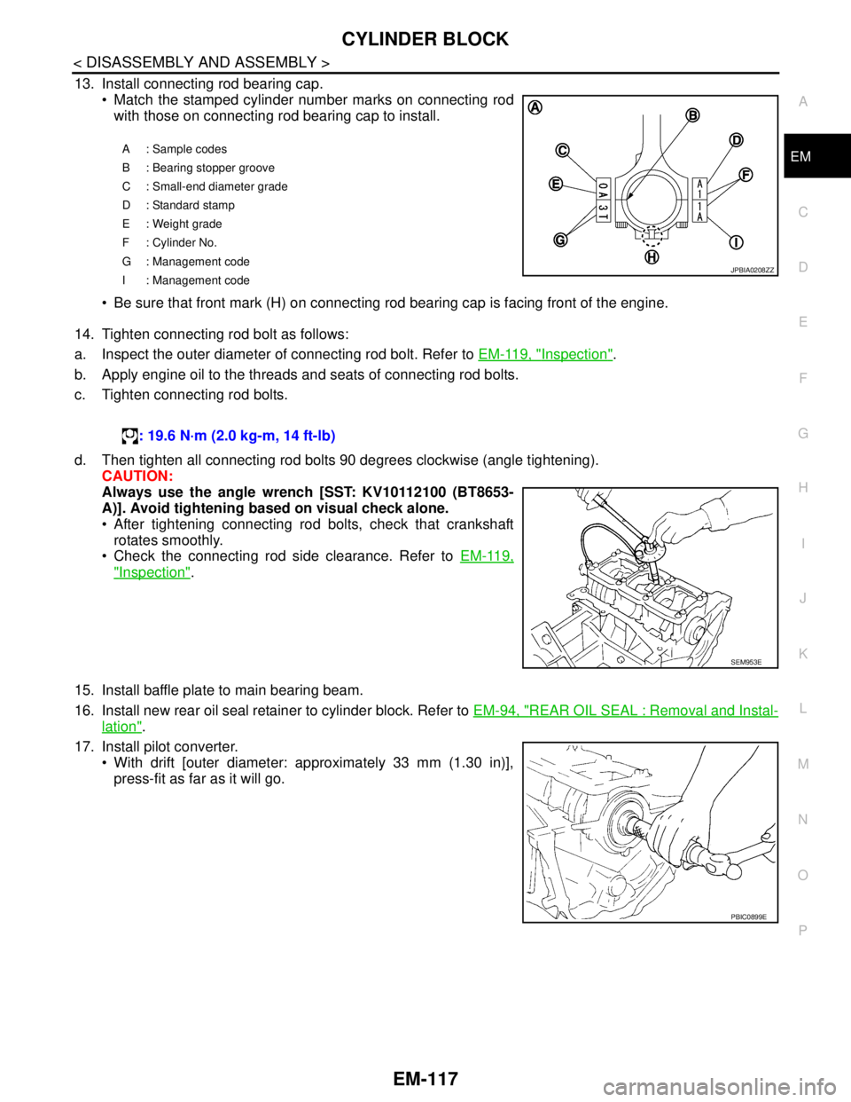
13. Install connecting rod bearing cap.
Match the stamped cylinder number marks on connecting rod
with those on connecting rod bearing cap to install.
Be sure that front mark (H) on connecting rod bearing cap is facing front of the engine.
14. Tighten connecting rod bolt as follows:
a. Inspect the outer diameter of connecting rod bolt. Refer to EM-119, "
Inspection".
b. Apply engine oil to the threads and seats of connecting rod bolts.
c. Tighten connecting rod bolts.
d. Then tighten all connecting rod bolts 90 degrees clockwise (angle tightening).
CAUTION:
Always use the angle wrench [SST: KV10112100 (BT8653-
A)]. Avoid tightening based on visual check alone.
After tightening connecting rod bolts, check that crankshaft
rotates smoothly.
Check the connecting rod side clearance. Refer to EM-119,
"Inspection".
15. Install baffle plate to main bearing beam.
16. Install new rear oil seal retainer to cylinder block. Refer to EM-94, "
REAR OIL SEAL : Removal and Instal-
lation".
17. Install pilot converter.
With drift [outer diameter: approximately 33 mm (1.30 in)],
press-fit as far as it will go.
A: Sample codes
B : Bearing stopper groove
C : Small-end diameter grade
D : Standard stamp
E : Weight grade
F : Cylinder No.
G : Management code
I : Management code
JPBIA0208ZZ
: 19.6 N·m (2.0 kg-m, 14 ft-lb)
SEM953E
PBIC0899E
Page 1995 of 5121
EM-120
< DISASSEMBLY AND ASSEMBLY >
CYLINDER BLOCK
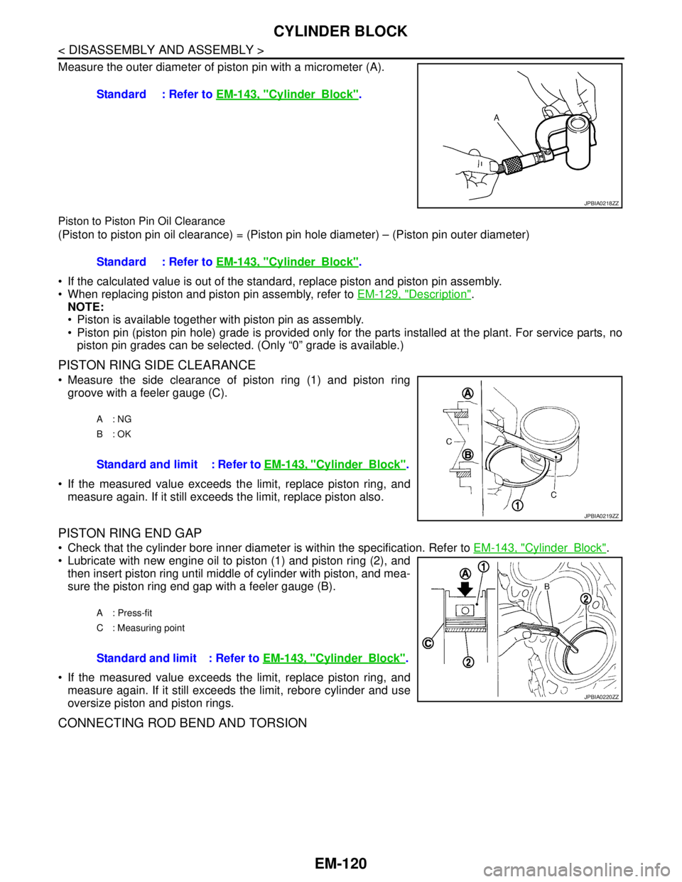
Measure the outer diameter of piston pin with a micrometer (A).
Piston to Piston Pin Oil Clearance
(Piston to piston pin oil clearance) = (Piston pin hole diameter) – (Piston pin outer diameter)
If the calculated value is out of the standard, replace piston and piston pin assembly.
When replacing piston and piston pin assembly, refer to EM-129, "
Description".
NOTE:
Piston is available together with piston pin as assembly.
Piston pin (piston pin hole) grade is provided only for the parts installed at the plant. For service parts, no
piston pin grades can be selected. (Only “0” grade is available.)
PISTON RING SIDE CLEARANCE
Measure the side clearance of piston ring (1) and piston ring
groove with a feeler gauge (C).
If the measured value exceeds the limit, replace piston ring, and
measure again. If it still exceeds the limit, replace piston also.
PISTON RING END GAP
Check that the cylinder bore inner diameter is within the specification. Refer to EM-143, "CylinderBlock".
Lubricate with new engine oil to piston (1) and piston ring (2), and
then insert piston ring until middle of cylinder with piston, and mea-
sure the piston ring end gap with a feeler gauge (B).
If the measured value exceeds the limit, replace piston ring, and
measure again. If it still exceeds the limit, rebore cylinder and use
oversize piston and piston rings.
CONNECTING ROD BEND AND TORSION
Standard : Refer to EM-143, "CylinderBlock".
JPBIA0218ZZ
Standard : Refer to EM-143, "CylinderBlock".
A: NG
B: OK
Standard and limit : Refer to EM-143, "CylinderBlock".
JPBIA0219ZZ
A : Press-fit
C : Measuring point
Standard and limit : Refer to EM-143, "CylinderBlock".
JPBIA0220ZZ
Page 1996 of 5121
CYLINDER BLOCK
EM-121
< DISASSEMBLY AND ASSEMBLY >
C
D
E
F
G
H
I
J
K
L
MA
EM
N
P O
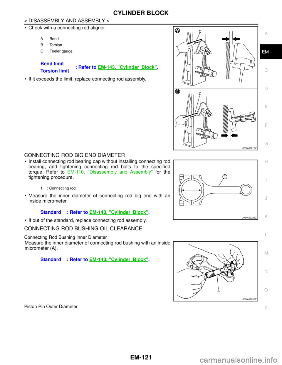
Check with a connecting rod aligner.
If it exceeds the limit, replace connecting rod assembly.
CONNECTING ROD BIG END DIAMETER
Install connecting rod bearing cap without installing connecting rod
bearing, and tightening connecting rod bolts to the specified
torque. Refer to EM-110, "
Disassembly and Assembly" for the
tightening procedure.
Measure the inner diameter of connecting rod big end with an
inside micrometer.
If out of the standard, replace connecting rod assembly.
CONNECTING ROD BUSHING OIL CLEARANCE
Connecting Rod Bushing Inner Diameter
Measure the inner diameter of connecting rod bushing with an inside
micrometer (A).
Piston Pin Outer Diameter
A: Bend
B: Torsion
C : Feeler gauge
Bend limit
: Refer to EM-143, "CylinderBlock".
Torsion limit
JPBIA0221ZZ
1 : Connecting rod
Standard : Refer to EM-143, "CylinderBlock".
JPBIA0222ZZ
Standard : Refer to EM-143, "CylinderBlock".
JPBIA0223ZZ
Page 2003 of 5121
EM-128
< DISASSEMBLY AND ASSEMBLY >
CYLINDER BLOCK
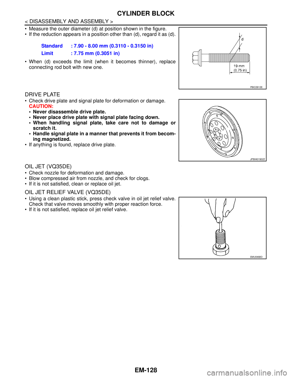
Measure the outer diameter (d) at position shown in the figure.
If the reduction appears in a position other than (d), regard it as (d).
When (d) exceeds the limit (when it becomes thinner), replace
connecting rod bolt with new one.
DRIVE PLATE
Check drive plate and signal plate for deformation or damage.
CAUTION:
Never disassemble drive plate.
Never place drive plate with signal plate facing down.
When handling signal plate, take care not to damage or
scratch it.
Handle signal plate in a manner that prevents it from becom-
ing magnetized.
If anything is found, replace drive plate.
OIL JET (VQ35DE)
Check nozzle for deformation and damage.
Blow compressed air from nozzle, and check for clogs.
If it is not satisfied, clean or replace oil jet.
OIL JET RELIEF VALVE (VQ35DE)
Using a clean plastic stick, press check valve in oil jet relief valve.
Check that valve moves smoothly with proper reaction force.
If it is not satisfied, replace oil jet relief valve.Standard : 7.90 - 8.00 mm (0.3110 - 0.3150 in)
Limit : 7.75 mm (0.3051 in)
PBIC0912E
JPBIA0192ZZ
EMU0468D
Page 2006 of 5121
HOW TO SELECT PISTON AND BEARING
EM-131
< DISASSEMBLY AND ASSEMBLY >
C
D
E
F
G
H
I
J
K
L
MA
EM
N
P O
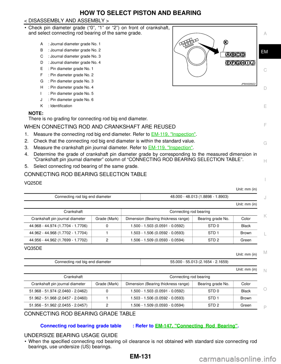
Check pin diameter grade (“0”, “1” or “2”) on front of crankshaft,
and select connecting rod bearing of the same grade.
NOTE:
There is no grading for connecting rod big end diameter.
WHEN CONNECTING ROD AND CRANKSHAFT ARE REUSED
1. Measure the connecting rod big end diameter. Refer to EM-119, "Inspection".
2. Check that the connecting rod big end diameter is within the standard value.
3. Measure the crankshaft pin journal diameter. Refer to EM-119, "
Inspection".
4. Determine the grade of crankshaft pin diameter grade by corresponding to the measured dimension in
“Crankshaft pin journal diameter” column of “CONNECTING ROD BEARING SELECTION TABLE”.
5. Select connecting rod bearing of the same grade.
CONNECTING ROD BEARING SELECTION TABLE
VQ25DE
Unit: mm (in)
Unit: mm (in)
VQ35DE
Unit: mm (in)
Unit: mm (in)
CONNECTING ROD BEARING GRADE TABLE
UNDERSIZE BEARING USAGE GUIDE
When the specified connecting rod bearing oil clearance is not obtained with standard size connecting rod
bearings, use undersize (US) bearings.
A : Journal diameter grade No. 1
B : Journal diameter grade No. 2
C : Journal diameter grade No. 3
D : Journal diameter grade No. 4
E : Pin diameter grade No. 1
F : Pin diameter grade No. 2
G : Pin diameter grade No. 3
H : Pin diameter grade No. 4
I : Pin diameter grade No. 5
J : Pin diameter grade No. 6
K : Identification
JPBIA0269ZZ
Connecting rod big end diameter 48.000 - 48.013 (1.8898 - 1.8903)
Crankshaft Connecting rod bearing
Crankshaft pin journal diameter Grade (Mark) Dimension (Bearing thickness range) Bearing grade No. Color
44.968 - 44.974 (1.7704 - 1.7706) 0 1.500 - 1.503 (0.0591 - 0.0592) STD 0 Black
44.962 - 44.968 (1.7702 - 1.7704) 1 1.503 - 1.506 (0.0592 - 0.0593) STD 1 Brown
44.956 - 44.962 (1.7699 - 1.7702) 2 1.506 - 1.509 (0.0593 - 0.0594) STD 2 Green
Connecting rod big end diameter 55.000 - 55.013 (2.1654 - 2.1659)
Crankshaft Connecting rod bearing
Crankshaft pin journal diameter Grade (Mark) Dimension (Bearing thickness range) Bearing grade No. Color
51.968 - 51.974 (2.0460 - 2.0462) 0 1.500 - 1.503 (0.0591 - 0.0592) STD 0 Black
51.962 - 51.968 (2.0457 - 2.0460) 1 1.503 - 1.506 (0.0592 - 0.0593) STD 1 Brown
51.956 - 51.962 (2.0455 - 2.0457) 2 1.506 - 1.509 (0.0593 - 0.0594) STD 2 Green
Connecting rod bearing grade table : Refer to EM-147, "ConnectingRodBearing".
Page 2029 of 5121

EX-6
< ON-VEHICLE REPAIR >
EXHAUST SYSTEM
Remove deposits from the sealing surface of each connection. Connect them securely to avoid
gases leakage.
When installing each mounting rubber, use silicon oil to avoid twisting.
Temporarily tighten mounting nuts and bolts. Check each part for unusual interference, and then
tighten them to the specified torque.
When installing each mounting rubber, avoid twisting or unusual extension in up/down, front/rear
and right/left directions.
InspectionINFOID:0000000003793263
INSPECTION AFTER INSTALLATION
Check clearance between tail tube and rear bumper is even.
With engine running, check exhaust tube joints for gas leakage and unusual noises.
Check to ensure that mounting brackets and mounting rubbers are installed properly and free from undue
stress. Improper installation could result in excessive noise and vibration.
Page 2061 of 5121
![NISSAN TEANA 2008 Service Manual EXL-32
< FUNCTION DIAGNOSIS >[XENON TYPE]
DIAGNOSIS SYSTEM (IPDM E/R)
DIAGNOSIS SYSTEM (IPDM E/R)
Diagnosis DescriptionINFOID:0000000003894259
AUTO ACTIVE TEST
Description
In auto active test mode, th NISSAN TEANA 2008 Service Manual EXL-32
< FUNCTION DIAGNOSIS >[XENON TYPE]
DIAGNOSIS SYSTEM (IPDM E/R)
DIAGNOSIS SYSTEM (IPDM E/R)
Diagnosis DescriptionINFOID:0000000003894259
AUTO ACTIVE TEST
Description
In auto active test mode, th](/manual-img/5/57391/w960_57391-2060.png)
EXL-32
< FUNCTION DIAGNOSIS >[XENON TYPE]
DIAGNOSIS SYSTEM (IPDM E/R)
DIAGNOSIS SYSTEM (IPDM E/R)
Diagnosis DescriptionINFOID:0000000003894259
AUTO ACTIVE TEST
Description
In auto active test mode, the IPDM E/R sends a drive signal to the following systems to check their operation.
Oil pressure warning lamp
Front wiper (LO, HI)
Parking lamps
License plate lamps
Tail lamps
Front fog lamps
Headlamps (LO, HI)
A/C compressor (magnet clutch)
Cooling fan
Operation Procedure
1. Close the hood and lift the wiper arms from the windshield. (Prevent windshield damage due to wiper
operation)
NOTE:
When auto active test is performed with hood opened, sprinkle water on windshield beforehand.
2. Turn ignition switch OFF.
3. Turn the ignition switch ON, and within 20 seconds, press the driver door switch 10 times. Then turn the
ignition switch OFF.
CAUTION:
Close passenger door.
4. Turn the ignition switch ON within 10 seconds. After that the horn sounds once and the auto active test
starts.
5. The oil pressure warning lamp starts blinking when the auto active test starts.
6. After a series of the following operations is repeated 3 times, auto active test is completed.
NOTE:
When auto active test mode has to be cancelled halfway through test, turn ignition switch OFF.
CAUTION:
If auto active test mode cannot be actuated, check door switch system. Refer to DLK-57,
"ComponentFunctionCheck".
Do not start the engine.
Inspection in Auto Active Test Mode
When auto active test mode is actuated, the following 5 steps are repeated 3 times.
Operation
sequenceInspection location Operation
A Oil pressure warning lamp Blinks continuously during operation of auto active test
1 Front wiper LO for 5 seconds → HI for 5 seconds
2 Parking lamps
License plate lamps
Tail lamps
Front fog lamps10 seconds
3 Headlamps LO ⇔ HI 5 times
4A/C compressor (magnet clutch) ON ⇔ OFF 5 times
5 Cooling fan LO for 5 seconds → MID for 3 seconds → HI for 2 seconds
Page 2201 of 5121
![NISSAN TEANA 2008 Service Manual EXL-172
< PRECAUTION >[XENON TYPE]
PRECAUTIONS
PRECAUTION
PRECAUTIONS
Precaution for Supplemental Restraint System (SRS) "AIR BAG" and "SEAT BELT
PRE-TENSIONER"
INFOID:0000000003813382
The Supplement NISSAN TEANA 2008 Service Manual EXL-172
< PRECAUTION >[XENON TYPE]
PRECAUTIONS
PRECAUTION
PRECAUTIONS
Precaution for Supplemental Restraint System (SRS) "AIR BAG" and "SEAT BELT
PRE-TENSIONER"
INFOID:0000000003813382
The Supplement](/manual-img/5/57391/w960_57391-2200.png)
EXL-172
< PRECAUTION >[XENON TYPE]
PRECAUTIONS
PRECAUTION
PRECAUTIONS
Precaution for Supplemental Restraint System (SRS) "AIR BAG" and "SEAT BELT
PRE-TENSIONER"
INFOID:0000000003813382
The Supplemental Restraint System such as “AIR BAG” and “SEAT BELT PRE-TENSIONER”, used along
with a front seat belt, helps to reduce the risk or severity of injury to the driver and front passenger for certain
types of collision. This system includes seat belt switch inputs and dual stage front air bag modules. The SRS
system uses the seat belt switches to determine the front air bag deployment, and may only deploy one front
air bag, depending on the severity of a collision and whether the front occupants are belted or unbelted.
Information necessary to service the system safely is included in the “SRS AIRBAG” and “SEAT BELT” of this
Service Manual.
WARNING:
To avoid rendering the SRS inoperative, which could increase the risk of personal injury or death in
the event of a collision which would result in air bag inflation, all maintenance must be performed by
an authorized NISSAN/INFINITI dealer.
Improper maintenance, including incorrect removal and installation of the SRS, can lead to personal
injury caused by unintentional activation of the system. For removal of Spiral Cable and Air Bag
Module, see the “SRS AIRBAG”.
Do not use electrical test equipment on any circuit related to the SRS unless instructed to in this
Service Manual. SRS wiring harnesses can be identified by yellow and/or orange harnesses or har-
ness connectors.
Precautions For Xenon Headlamp ServiceINFOID:0000000003773614
WARNING:
Comply with the following warnings to prevent any serious accident.
Disconnect the battery cable (negative terminal) or the power supply fuse before installing, remov-
ing, or touching the xenon headlamp (bulb included). The xenon headlamp contains high-voltage
generated parts.
Never work with wet hands.
Check the xenon headlamp ON-OFF status after assembling it to the vehicle. Never turn the xenon
headlamp ON in other conditions. Connect the power supply to the vehicle-side connector.
(Turning it ON outside the lamp case may cause fire or visual impairments.)
Never touch the bulb glass immediately after turning it OFF. It is extremely hot.
CAUTION:
Comply with the following cautions to prevent any error and malfunction.
Install the xenon bulb securely. (Insufficient bulb socket installation may melt the bulb, the connec-
tor, the housing, etc. by high-voltage leakage or corona discharge.)
Never perform HID circuit inspection with a tester.
Never touch the xenon bulb glass with hands. Never put oil and grease on it.
Dispose of the used xenon bulb after packing it in thick vinyl without breaking it.
Never wipe out dirt and contamination with organic solvent (thinner, gasoline, etc.).