2008 NISSAN TEANA check oil
[x] Cancel search: check oilPage 2490 of 5121
FSU-16
< REMOVAL AND INSTALLATION >
FRONT SUSPENSION MEMBER
REMOVAL AND INSTALLATION
FRONT SUSPENSION MEMBER
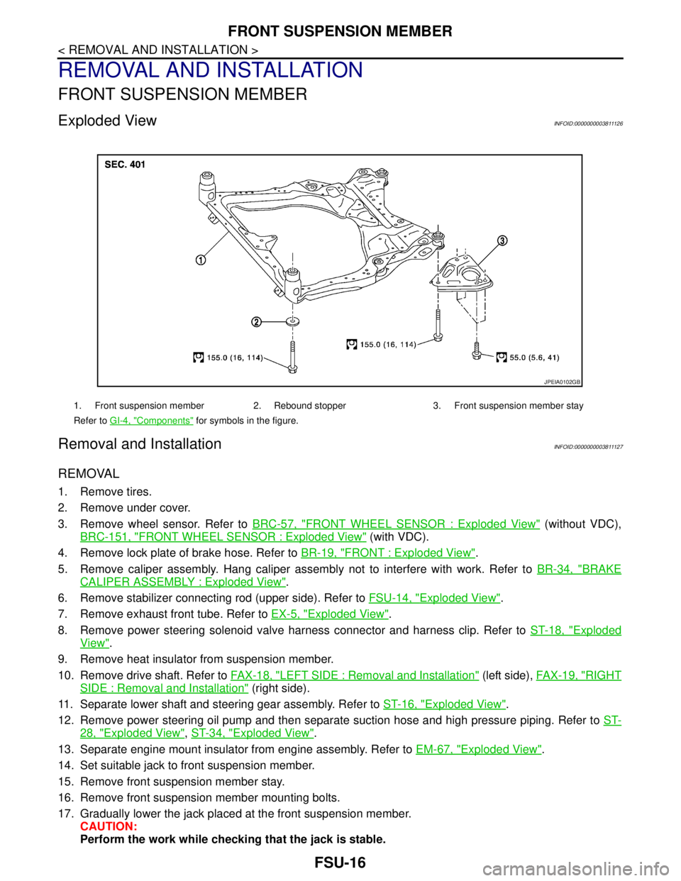
Exploded ViewINFOID:0000000003811126
Removal and InstallationINFOID:0000000003811127
REMOVAL
1. Remove tires.
2. Remove under cover.
3. Remove wheel sensor. Refer to BRC-57, "
FRONT WHEEL SENSOR : Exploded View" (without VDC),
BRC-151, "
FRONT WHEEL SENSOR : Exploded View" (with VDC).
4. Remove lock plate of brake hose. Refer to BR-19, "
FRONT : Exploded View".
5. Remove caliper assembly. Hang caliper assembly not to interfere with work. Refer to BR-34, "
BRAKE
CALIPER ASSEMBLY : Exploded View".
6. Remove stabilizer connecting rod (upper side). Refer to FSU-14, "
Exploded View".
7. Remove exhaust front tube. Refer to EX-5, "
Exploded View".
8. Remove power steering solenoid valve harness connector and harness clip. Refer to ST-18, "
Exploded
View".
9. Remove heat insulator from suspension member.
10. Remove drive shaft. Refer to FAX-18, "
LEFT SIDE : Removal and Installation" (left side), FAX-19, "RIGHT
SIDE : Removal and Installation" (right side).
11. Separate lower shaft and steering gear assembly. Refer to ST-16, "
Exploded View".
12. Remove power steering oil pump and then separate suction hose and high pressure piping. Refer to ST-
28, "Exploded View", ST-34, "Exploded View".
13. Separate engine mount insulator from engine assembly. Refer to EM-67, "
Exploded View".
14. Set suitable jack to front suspension member.
15. Remove front suspension member stay.
16. Remove front suspension member mounting bolts.
17. Gradually lower the jack placed at the front suspension member.
CAUTION:
Perform the work while checking that the jack is stable.
1. Front suspension member 2. Rebound stopper 3. Front suspension member stay
Refer to GI-4, "
Components" for symbols in the figure.
JPEIA0102GB
Page 2494 of 5121

GI-1
GENERAL INFORMATION
C
D
E
F
G
H
I
J
K
L
MB
GI
SECTION GI
N
O
P
CONTENTS
GENERAL INFORMATION
HOW TO USE THIS MANUAL ......................3
HOW TO USE THIS MANUAL ............................3
Description ................................................................3
Terms ........................................................................3
Units ..........................................................................3
Contents ....................................................................3
Relation between Illustrations and Descriptions .......4
Components ..............................................................4
HOW TO FOLLOW TROUBLE DIAGNOSES .....6
Description ................................................................6
How to Follow Test Groups in Trouble Diagnosis ......6
Key to Symbols Signifying Measurements or Pro-
cedures .....................................................................
7
HOW TO READ WIRING DIAGRAMS ................9
Connector Symbols ...................................................9
Sample/Wiring Diagram -Example- .........................10
Description ..............................................................11
ABBREVIATIONS ..............................................13
Abbreviation List ......................................................13
TIGHTENING TORQUE OF STANDARD
BOLTS ................................................................
14
Description ..............................................................14
Tightening Torque Table (New Standard Includ-
ed) ...........................................................................
14
TERMINOLOGY .................................................17
SAE J1930 Terminology List ...................................17
FEATURES OF NEW MODEL .....................21
IDENTIFICATION INFORMATION .....................21
Model Variation .......................................................21
Information About Identification or Model Code ......21
Dimensions .............................................................23
Wheels & Tires ........................................................23
PRECAUTION ..............................................24
PRECAUTIONS .................................................24
Description ...............................................................24
Precaution for Supplemental Restraint System
(SRS) "AIR BAG" and "SEAT BELT PRE-TEN-
SIONER" .................................................................
24
Precautions For Xenon Headlamp Service .............24
Precaution Necessary for Steering Wheel Rota-
tion after Battery Disconnect ...................................
24
Precaution for Procedure without Cowl Top Cover ....25
General Precautions ................................................25
Three Way Catalyst .................................................27
Multiport Fuel Injection System or Engine Control
System .....................................................................
27
Hoses ......................................................................27
Engine Oils ..............................................................28
Air Conditioning .......................................................28
Fuel ..........................................................................29
LIFTING POINT .................................................30
Commercial Service Tools .......................................30
Garage Jack and Safety Stand and 2-Pole Lift .......30
Board-On Lift ...........................................................31
TOW TRUCK TOWING .....................................32
Tow Truck Towing ...................................................32
Vehicle Recovery (Freeing a Stuck Vehicle) ...........32
BASIC INSPECTION ...................................34
SERVICE INFORMATION FOR ELECTRICAL
INCIDENT ..........................................................
34
Work Flow ................................................................34
Control Units and Electrical Parts ............................34
Intermittent Incident .................................................35
Circuit Inspection .....................................................37
CONSULT-III/GST CHECKING SYSTEM .........43
Description ...............................................................43
CONSULT-III Function and System Application*1 ....43
CONSULT-III/GST Data Link Connector (DLC)
Circuit ......................................................................
43
Page 2517 of 5121
GI-24
< PRECAUTION >
PRECAUTIONS
PRECAUTION
PRECAUTIONS
DescriptionINFOID:0000000003852776
Observe the following precautions to ensure safe and proper servicing. These precautions are not
described in each individual section.
Precaution for Supplemental Restraint System (SRS) "AIR BAG" and "SEAT BELT
PRE-TENSIONER"
INFOID:0000000003852830
The Supplemental Restraint System such as “AIR BAG” and “SEAT BELT PRE-TENSIONER”, used along
with a front seat belt, helps to reduce the risk or severity of injury to the driver and front passenger for certain
types of collision. Information necessary to service the system safely is included in the “SRS AIRBAG” and
“SEAT BELT” of this Service Manual.
WARNING:
To avoid rendering the SRS inoperative, which could increase the risk of personal injury or death in
the event of a collision which would result in air bag inflation, all maintenance must be performed by
an authorized NISSAN/INFINITI dealer.
Improper maintenance, including incorrect removal and installation of the SRS, can lead to personal
injury caused by unintentional activation of the system. For removal of Spiral Cable and Air Bag
Module, see the “SRS AIRBAG”.
Never use electrical test equipment on any circuit related to the SRS unless instructed to in this Ser-
vice Manual. SRS wiring harnesses can be identified by yellow and/or orange harnesses or harness
connectors.
Precautions For Xenon Headlamp ServiceINFOID:0000000003852778
WARNING:
Comply with the following warnings to prevent any serious accident.
Disconnect the battery cable (negative terminal) or the power supply fuse before installing, remov-
ing, or touching the xenon headlamp (bulb included). The xenon headlamp contains high-voltage
generated parts.
Never work with wet hands.
Check the xenon headlamp ON-OFF status after assembling it to the vehicle. Never turn the xenon
headlamp ON in other conditions. Connect the power supply to the vehicle-side connector.
(Turning it ON outside the lamp case may cause fire or visual impairments.)
Never touch the bulb glass immediately after turning it OFF. It is extremely hot.
CAUTION:
Comply with the following cautions to prevent any error and malfunction.
Install the xenon bulb securely. (Insufficient bulb socket installation may melt the bulb, the connec-
tor, the housing, etc. by high-voltage leakage or corona discharge.)
Never perform HID circuit inspection with a tester.
Never touch the xenon bulb glass with hands. Never put oil and grease on it.
Dispose of the used xenon bulb after packing it in thick vinyl without breaking it.
Never wipe out dirt and contamination with organic solvent (thinner, gasoline, etc.).
Precaution Necessary for Steering Wheel Rotation after Battery Disconnect
INFOID:0000000003852856
NOTE:
Before removing and installing any control units, first turn the push-button ignition switch to the LOCK posi-
tion, then disconnect both battery cables.
After finishing work, confirm that all control unit connectors are connected properly, then re-connect both
battery cables.
Always use CONSULT-III to perform self-diagnosis as a part of each function inspection after finishing work.
If a DTC is detected, perform trouble diagnosis according to self-diagnosis results.
This vehicle is equipped with a push-button ignition switch and a steering lock unit.
If the battery is disconnected or discharged, the steering wheel will lock and cannot be turned.
Page 2519 of 5121
GI-26
< PRECAUTION >
PRECAUTIONS
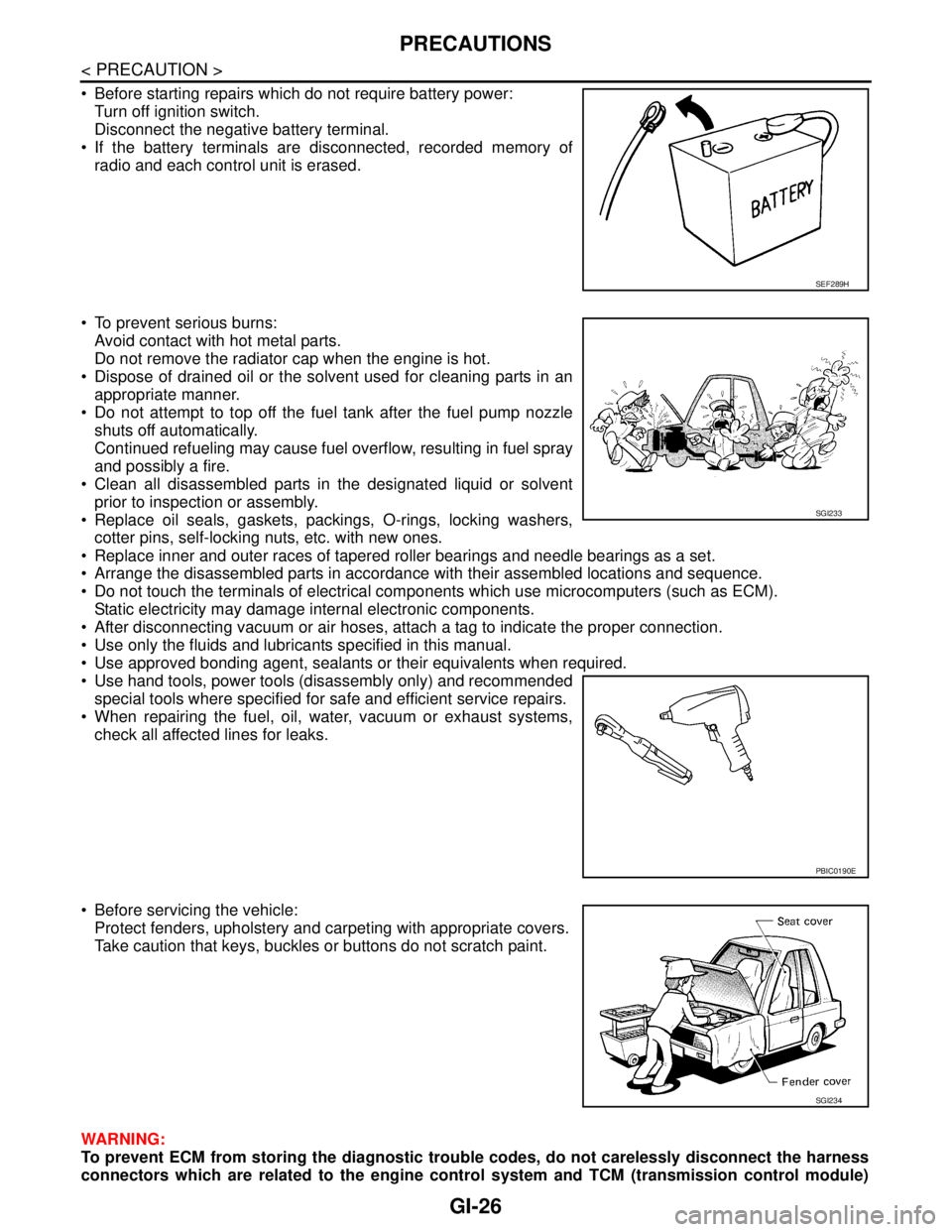
Before starting repairs which do not require battery power:
Turn off ignition switch.
Disconnect the negative battery terminal.
If the battery terminals are disconnected, recorded memory of
radio and each control unit is erased.
To prevent serious burns:
Avoid contact with hot metal parts.
Do not remove the radiator cap when the engine is hot.
Dispose of drained oil or the solvent used for cleaning parts in an
appropriate manner.
Do not attempt to top off the fuel tank after the fuel pump nozzle
shuts off automatically.
Continued refueling may cause fuel overflow, resulting in fuel spray
and possibly a fire.
Clean all disassembled parts in the designated liquid or solvent
prior to inspection or assembly.
Replace oil seals, gaskets, packings, O-rings, locking washers,
cotter pins, self-locking nuts, etc. with new ones.
Replace inner and outer races of tapered roller bearings and needle bearings as a set.
Arrange the disassembled parts in accordance with their assembled locations and sequence.
Do not touch the terminals of electrical components which use microcomputers (such as ECM).
Static electricity may damage internal electronic components.
After disconnecting vacuum or air hoses, attach a tag to indicate the proper connection.
Use only the fluids and lubricants specified in this manual.
Use approved bonding agent, sealants or their equivalents when required.
Use hand tools, power tools (disassembly only) and recommended
special tools where specified for safe and efficient service repairs.
When repairing the fuel, oil, water, vacuum or exhaust systems,
check all affected lines for leaks.
Before servicing the vehicle:
Protect fenders, upholstery and carpeting with appropriate covers.
Take caution that keys, buckles or buttons do not scratch paint.
WARNING:
To prevent ECM from storing the diagnostic trouble codes, do not carelessly disconnect the harness
connectors which are related to the engine control system and TCM (transmission control module)
SEF289H
SGI233
PBIC0190E
SGI234
Page 2528 of 5121
SERVICE INFORMATION FOR ELECTRICAL INCIDENT
GI-35
< BASIC INSPECTION >
C
D
E
F
G
H
I
J
K
L
MB
GI
N
O
P
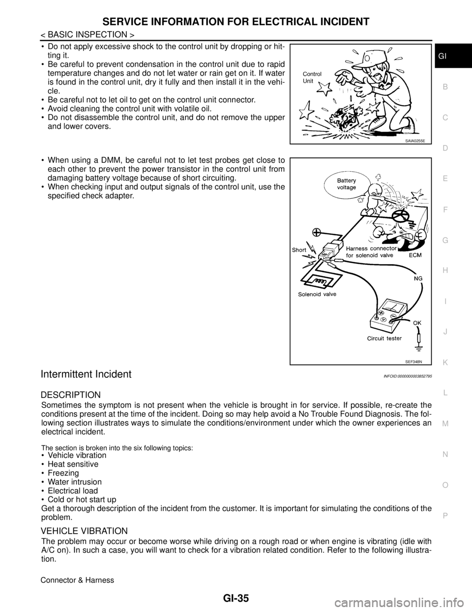
Do not apply excessive shock to the control unit by dropping or hit-
ting it.
Be careful to prevent condensation in the control unit due to rapid
temperature changes and do not let water or rain get on it. If water
is found in the control unit, dry it fully and then install it in the vehi-
cle.
Be careful not to let oil to get on the control unit connector.
Avoid cleaning the control unit with volatile oil.
Do not disassemble the control unit, and do not remove the upper
and lower covers.
When using a DMM, be careful not to let test probes get close to
each other to prevent the power transistor in the control unit from
damaging battery voltage because of short circuiting.
When checking input and output signals of the control unit, use the
specified check adapter.
Intermittent IncidentINFOID:0000000003852795
DESCRIPTION
Sometimes the symptom is not present when the vehicle is brought in for service. If possible, re-create the
conditions present at the time of the incident. Doing so may help avoid a No Trouble Found Diagnosis. The fol-
lowing section illustrates ways to simulate the conditions/environment under which the owner experiences an
electrical incident.
The section is broken into the six following topics: Vehicle vibration
Heat sensitive
Freezing
Water intrusion
Electrical load
Cold or hot start up
Get a thorough description of the incident from the customer. It is important for simulating the conditions of the
problem.
VEHICLE VIBRATION
The problem may occur or become worse while driving on a rough road or when engine is vibrating (idle with
A/C on). In such a case, you will want to check for a vibration related condition. Refer to the following illustra-
tion.
Connector & Harness
SAIA0255E
SEF348N
Page 2580 of 5121
COMPRESSOR SYSTEM SYMPTOMS
HA-11
< SYMPTOM DIAGNOSIS >
C
D
E
F
G
H
J
K
L
MA
B
HA
N
O
P
COMPRESSOR SYSTEM SYMPTOMS
Symptom TableINFOID:0000000003795808
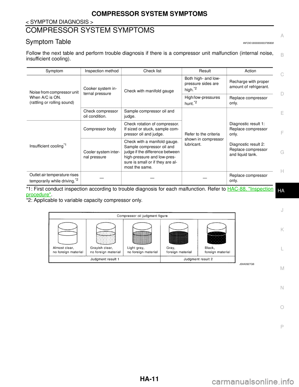
Follow the next table and perform trouble diagnosis if there is a compressor unit malfunction (internal noise,
insufficient cooling).
*1: First conduct inspection according to trouble diagnosis for each malfunction. Refer to HAC-88, "
Inspection
procedure".
*2: Applicable to variable capacity compressor only.
Symptom Inspection method Check list Result Action
Noise from compressor unit
When A/C is ON.
(rattling or rolling sound)Cooker system in-
ternal pressureCheck with manifold gaugeBoth high- and low-
pressure sides are
high.
*2
Recharge with proper
amount of refrigerant.
High/low-pressures
hunt.
*2Replace compressor
only.
Check compressor
oil condition.Sample compressor oil and
judge.
Refer to the criteria
shown in compressor
lubricant.Diagnostic result 1:
Replace compressor
only.
Diagnostic result 2:
Replace compressor
and liquid tank. Insufficient cooling
*1
Compressor bodyCheck rotation of compressor.
If sized or stuck, sample com-
pressor oil and judge.
Cooler system inter-
nal pressureCheck with a manifold gauge.
Sample compressor oil and
judge if the difference between
high-pressure and low-pres-
sure is small or if they are al-
most the same.
Outlet air temperature rises
temporarily while driving.
*2—— —Replace compressor
only.
JSIIA0927GB
Page 2582 of 5121
PRECAUTIONS
HA-13
< PRECAUTION >
C
D
E
F
G
H
J
K
L
MA
B
HA
N
O
P
Precaution for Procedure without Cowl Top CoverINFOID:0000000003795884
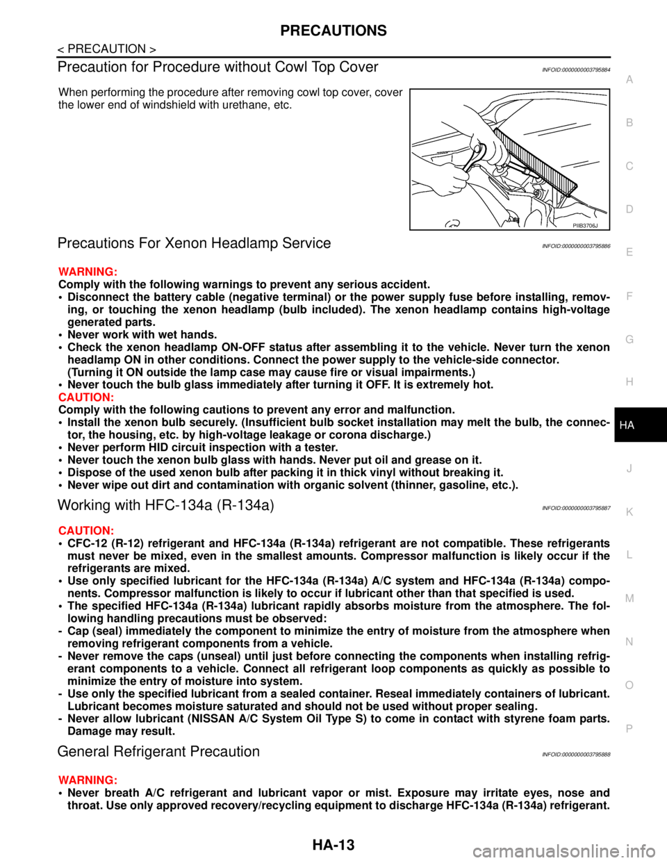
When performing the procedure after removing cowl top cover, cover
the lower end of windshield with urethane, etc.
Precautions For Xenon Headlamp ServiceINFOID:0000000003795886
WARNING:
Comply with the following warnings to prevent any serious accident.
Disconnect the battery cable (negative terminal) or the power supply fuse before installing, remov-
ing, or touching the xenon headlamp (bulb included). The xenon headlamp contains high-voltage
generated parts.
Never work with wet hands.
Check the xenon headlamp ON-OFF status after assembling it to the vehicle. Never turn the xenon
headlamp ON in other conditions. Connect the power supply to the vehicle-side connector.
(Turning it ON outside the lamp case may cause fire or visual impairments.)
Never touch the bulb glass immediately after turning it OFF. It is extremely hot.
CAUTION:
Comply with the following cautions to prevent any error and malfunction.
Install the xenon bulb securely. (Insufficient bulb socket installation may melt the bulb, the connec-
tor, the housing, etc. by high-voltage leakage or corona discharge.)
Never perform HID circuit inspection with a tester.
Never touch the xenon bulb glass with hands. Never put oil and grease on it.
Dispose of the used xenon bulb after packing it in thick vinyl without breaking it.
Never wipe out dirt and contamination with organic solvent (thinner, gasoline, etc.).
Working with HFC-134a (R-134a)INFOID:0000000003795887
CAUTION:
CFC-12 (R-12) refrigerant and HFC-134a (R-134a) refrigerant are not compatible. These refrigerants
must never be mixed, even in the smallest amounts. Compressor malfunction is likely occur if the
refrigerants are mixed.
Use only specified lubricant for the HFC-134a (R-134a) A/C system and HFC-134a (R-134a) compo-
nents. Compressor malfunction is likely to occur if lubricant other than that specified is used.
The specified HFC-134a (R-134a) lubricant rapidly absorbs moisture from the atmosphere. The fol-
lowing handling precautions must be observed:
- Cap (seal) immediately the component to minimize the entry of moisture from the atmosphere when
removing refrigerant components from a vehicle.
- Never remove the caps (unseal) until just before connecting the components when installing refrig-
erant components to a vehicle. Connect all refrigerant loop components as quickly as possible to
minimize the entry of moisture into system.
- Use only the specified lubricant from a sealed container. Reseal immediately containers of lubricant.
Lubricant becomes moisture saturated and should not be used without proper sealing.
- Never allow lubricant (NISSAN A/C System Oil Type S) to come in contact with styrene foam parts.
Damage may result.
General Refrigerant PrecautionINFOID:0000000003795888
WARNING:
Never breath A/C refrigerant and lubricant vapor or mist. Exposure may irritate eyes, nose and
throat. Use only approved recovery/recycling equipment to discharge HFC-134a (R-134a) refrigerant.
PIIB3706J
Page 2584 of 5121
PRECAUTIONS
HA-15
< PRECAUTION >
C
D
E
F
G
H
J
K
L
MA
B
HA
N
O
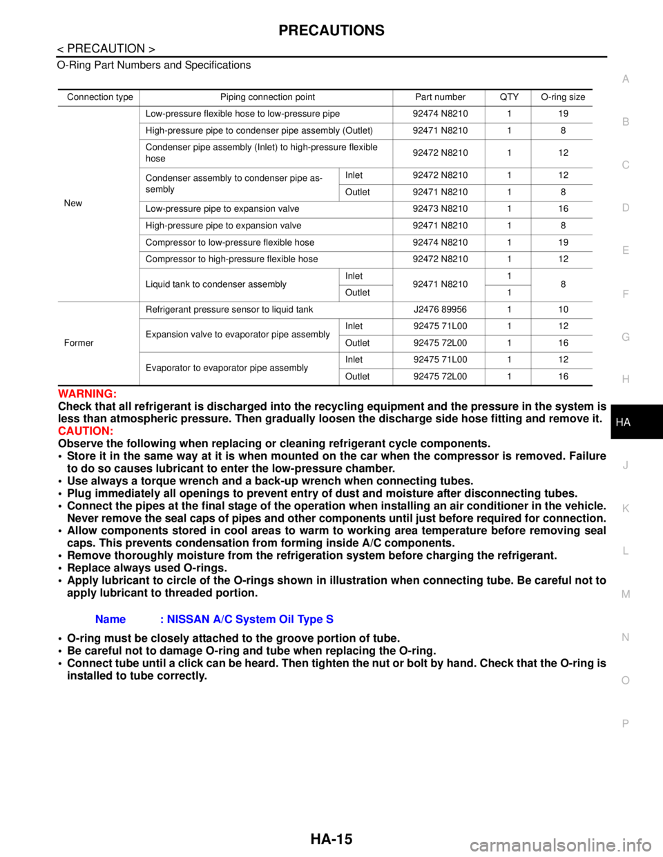
P O-Ring Part Numbers and Specifications
WARNING:
Check that all refrigerant is discharged into the recycling equipment and the pressure in the system is
less than atmospheric pressure. Then gradually loosen the discharge side hose fitting and remove it.
CAUTION:
Observe the following when replacing or cleaning refrigerant cycle components.
Store it in the same way at it is when mounted on the car when the compressor is removed. Failure
to do so causes lubricant to enter the low-pressure chamber.
Use always a torque wrench and a back-up wrench when connecting tubes.
Plug immediately all openings to prevent entry of dust and moisture after disconnecting tubes.
Connect the pipes at the final stage of the operation when installing an air conditioner in the vehicle.
Never remove the seal caps of pipes and other components until just before required for connection.
Allow components stored in cool areas to warm to working area temperature before removing seal
caps. This prevents condensation from forming inside A/C components.
Remove thoroughly moisture from the refrigeration system before charging the refrigerant.
Replace always used O-rings.
Apply lubricant to circle of the O-rings shown in illustration when connecting tube. Be careful not to
apply lubricant to threaded portion.
O-ring must be closely attached to the groove portion of tube.
Be careful not to damage O-ring and tube when replacing the O-ring.
Connect tube until a click can be heard. Then tighten the nut or bolt by hand. Check that the O-ring is
installed to tube correctly.
Connection type Piping connection point Part number QTY O-ring size
NewLow-pressure flexible hose to low-pressure pipe 92474 N8210 1 19
High-pressure pipe to condenser pipe assembly (Outlet) 92471 N8210 1 8
Condenser pipe assembly (Inlet) to high-pressure flexible
hose92472 N8210 1 12
Condenser assembly to condenser pipe as-
semblyInlet 92472 N8210 1 12
Outlet 92471 N8210 1 8
Low-pressure pipe to expansion valve 92473 N8210 1 16
High-pressure pipe to expansion valve 92471 N8210 1 8
Compressor to low-pressure flexible hose 92474 N8210 1 19
Compressor to high-pressure flexible hose 92472 N8210 1 12
Liquid tank to condenser assemblyInlet
92471 N82101
8
Outlet 1
FormerRefrigerant pressure sensor to liquid tank J2476 89956 1 10
Expansion valve to evaporator pipe assemblyInlet 92475 71L00 1 12
Outlet 92475 72L00 1 16
Evaporator to evaporator pipe assemblyInlet 92475 71L00 1 12
Outlet 92475 72L00 1 16
Name : NISSAN A/C System Oil Type S