2008 NISSAN TEANA check oil
[x] Cancel search: check oilPage 1952 of 5121
ENGINE STAND SETTING
EM-77
< DISASSEMBLY AND ASSEMBLY >
C
D
E
F
G
H
I
J
K
L
MA
EM
N
P O
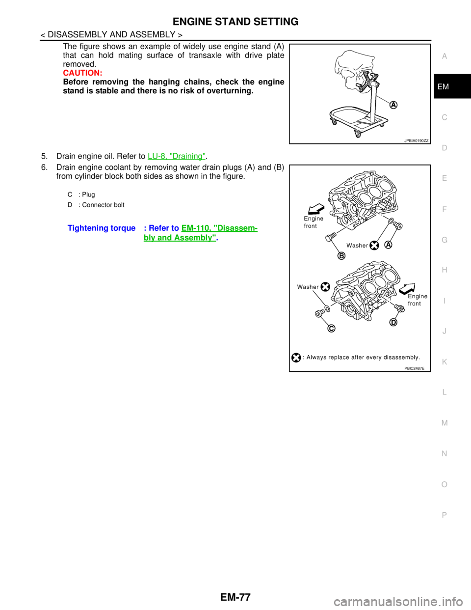
The figure shows an example of widely use engine stand (A)
that can hold mating surface of transaxle with drive plate
removed.
CAUTION:
Before removing the hanging chains, check the engine
stand is stable and there is no risk of overturning.
5. Drain engine oil. Refer to LU-8, "
Draining".
6. Drain engine coolant by removing water drain plugs (A) and (B)
from cylinder block both sides as shown in the figure.
JPBIA0190ZZ
C: Plug
D : Connector bolt
Tightening torque : Refer to EM-110, "Disassem-
bly and Assembly".
PBIC2487E
Page 1957 of 5121
EM-82
< DISASSEMBLY AND ASSEMBLY >
REAR TIMING CHAIN CASE
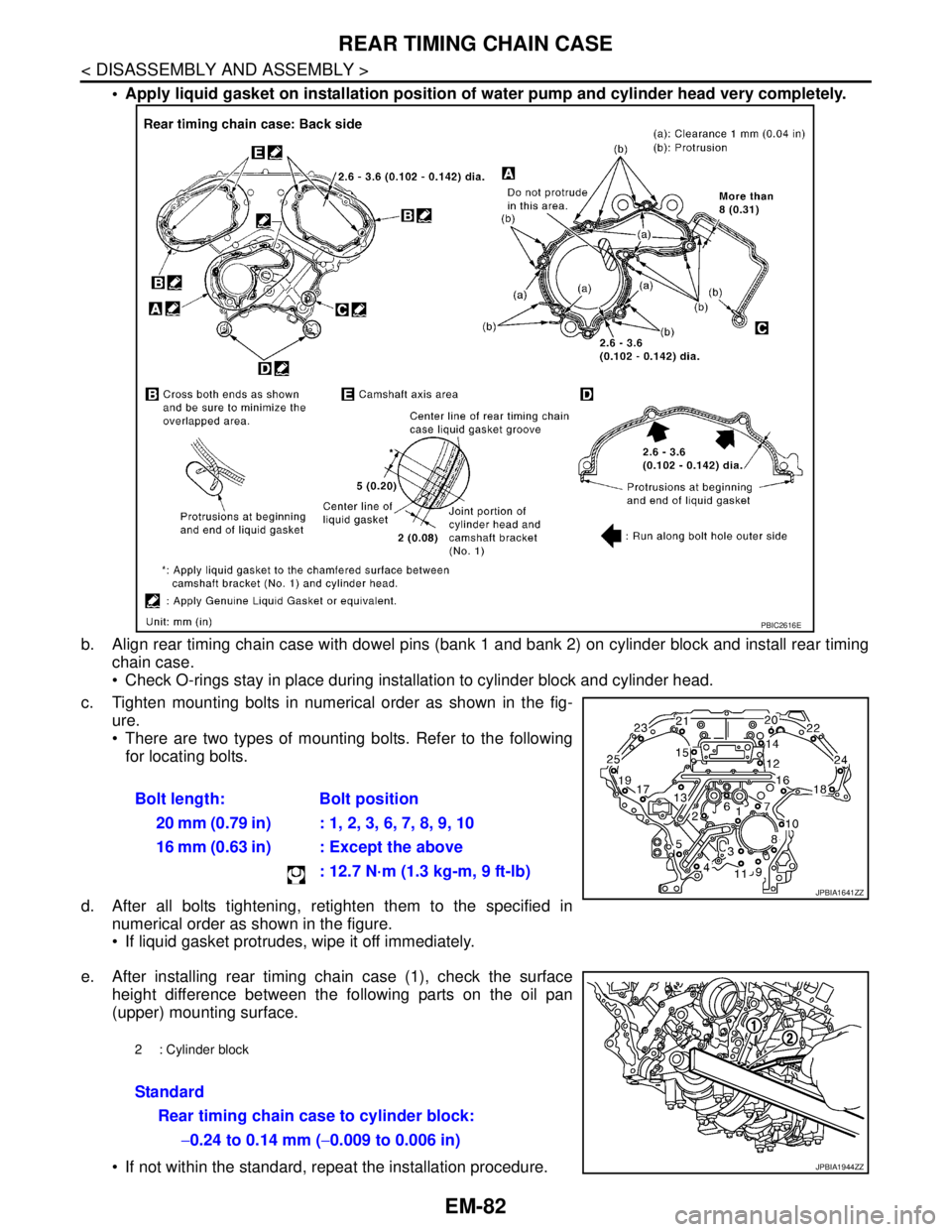
Apply liquid gasket on installation position of water pump and cylinder head very completely.
b. Align rear timing chain case with dowel pins (bank 1 and bank 2) on cylinder block and install rear timing
chain case.
Check O-rings stay in place during installation to cylinder block and cylinder head.
c. Tighten mounting bolts in numerical order as shown in the fig-
ure.
There are two types of mounting bolts. Refer to the following
for locating bolts.
d. After all bolts tightening, retighten them to the specified in
numerical order as shown in the figure.
If liquid gasket protrudes, wipe it off immediately.
e. After installing rear timing chain case (1), check the surface
height difference between the following parts on the oil pan
(upper) mounting surface.
If not within the standard, repeat the installation procedure.Bolt length: Bolt position
20 mm (0.79 in) : 1, 2, 3, 6, 7, 8, 9, 10
16 mm (0.63 in) : Except the above
: 12.7 N·m (1.3 kg-m, 9 ft-lb)
PBIC2616E
JPBIA1641ZZ
2 : Cylinder block
Standard
Rear timing chain case to cylinder block:
−0.24 to 0.14 mm (−0.009 to 0.006 in)
JPBIA1944ZZ
Page 1958 of 5121
REAR TIMING CHAIN CASE
EM-83
< DISASSEMBLY AND ASSEMBLY >
C
D
E
F
G
H
I
J
K
L
MA
EM
N
P O
2. Install water pump with new O-rings. Refer to CO-18, "Exploded View".
3. Install front timing chain case and timing chain. Refer to EM-52, "
Exploded View".
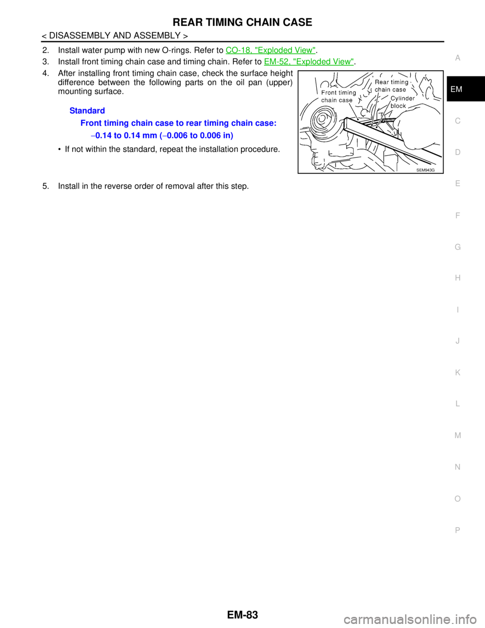
4. After installing front timing chain case, check the surface height
difference between the following parts on the oil pan (upper)
mounting surface.
If not within the standard, repeat the installation procedure.
5. Install in the reverse order of removal after this step.Standard
Front timing chain case to rear timing chain case:
−0.14 to 0.14 mm (−0.006 to 0.006 in)
SEM943G
Page 1966 of 5121
CAMSHAFT
EM-91
< DISASSEMBLY AND ASSEMBLY >
C
D
E
F
G
H
I
J
K
L
MA
EM
N
P O
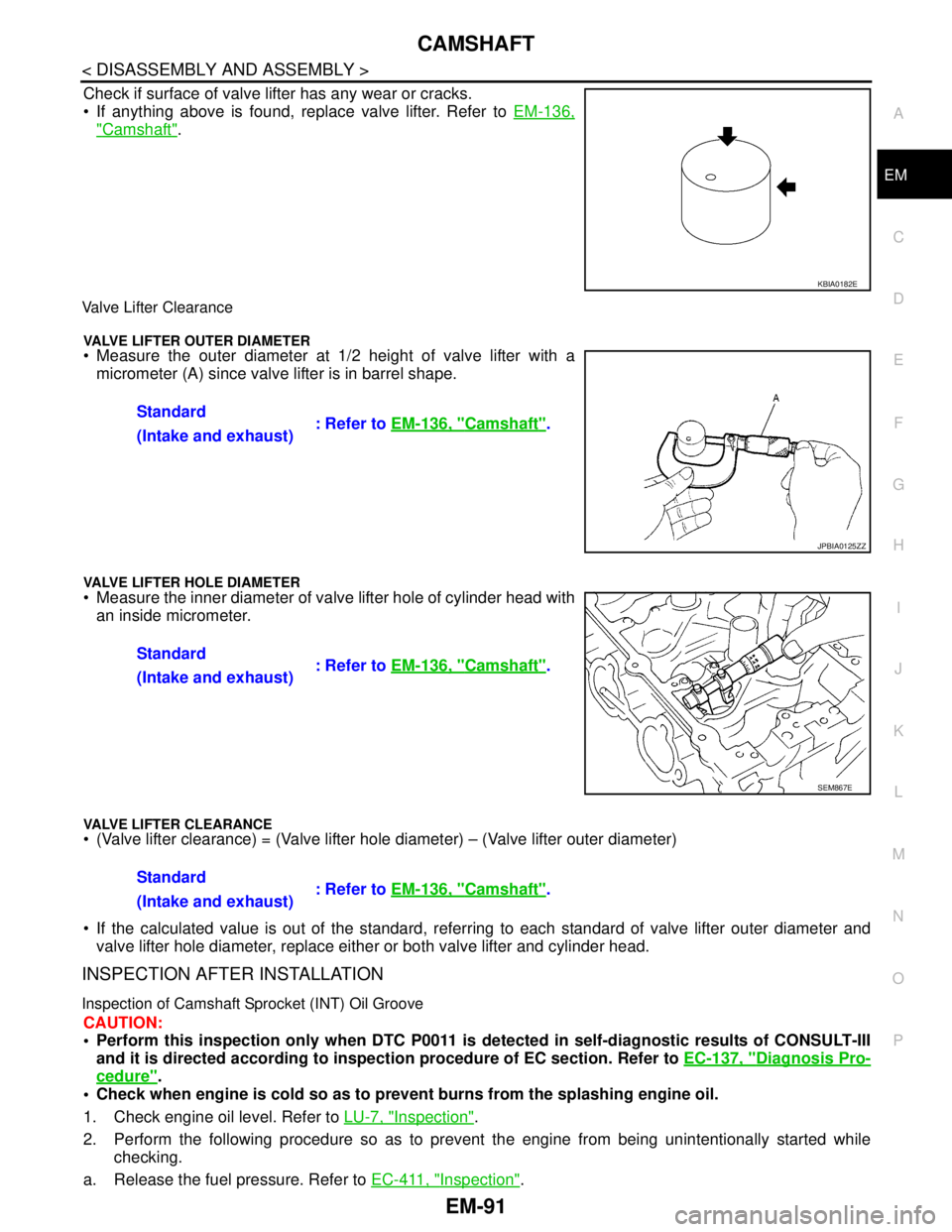
Check if surface of valve lifter has any wear or cracks.
If anything above is found, replace valve lifter. Refer to EM-136,
"Camshaft".
Valve Lifter Clearance
VALVE LIFTER OUTER DIAMETER Measure the outer diameter at 1/2 height of valve lifter with a
micrometer (A) since valve lifter is in barrel shape.
VALVE LIFTER HOLE DIAMETER Measure the inner diameter of valve lifter hole of cylinder head with
an inside micrometer.
VALVE LIFTER CLEARANCE (Valve lifter clearance) = (Valve lifter hole diameter) – (Valve lifter outer diameter)
If the calculated value is out of the standard, referring to each standard of valve lifter outer diameter and
valve lifter hole diameter, replace either or both valve lifter and cylinder head.
INSPECTION AFTER INSTALLATION
Inspection of Camshaft Sprocket (INT) Oil Groove
CAUTION:
Perform this inspection only when DTC P0011 is detected in self-diagnostic results of CONSULT-III
and it is directed according to inspection procedure of EC section. Refer to EC-137, "
Diagnosis Pro-
cedure".
Check when engine is cold so as to prevent burns from the splashing engine oil.
1. Check engine oil level. Refer to LU-7, "
Inspection".
2. Perform the following procedure so as to prevent the engine from being unintentionally started while
checking.
a. Release the fuel pressure. Refer to EC-411, "
Inspection".
KBIA0182E
Standard
: Refer to EM-136, "Camshaft".
(Intake and exhaust)
JPBIA0125ZZ
Standard
: Refer to EM-136, "Camshaft".
(Intake and exhaust)
SEM867E
Standard
: Refer to EM-136, "Camshaft".
(Intake and exhaust)
Page 1967 of 5121
EM-92
< DISASSEMBLY AND ASSEMBLY >
CAMSHAFT
b. Disconnect ignition coil and injector harness connectors. Refer to EM-49, "Exploded View" and EM-44,
"Exploded View".
3. Remove intake valve timing control solenoid valve. Refer to EM-79, "
Exploded View".
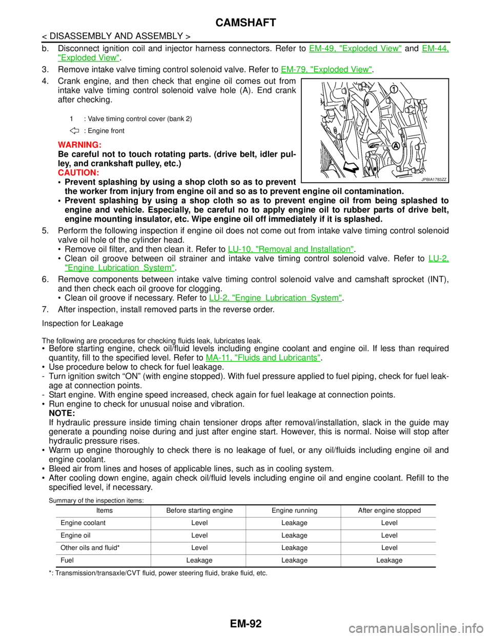
4. Crank engine, and then check that engine oil comes out from
intake valve timing control solenoid valve hole (A). End crank
after checking.
WARNING:
Be careful not to touch rotating parts. (drive belt, idler pul-
ley, and crankshaft pulley, etc.)
CAUTION:
Prevent splashing by using a shop cloth so as to prevent
the worker from injury from engine oil and so as to prevent engine oil contamination.
Prevent splashing by using a shop cloth so as to prevent engine oil from being splashed to
engine and vehicle. Especially, be careful no to apply engine oil to rubber parts of drive belt,
engine mounting insulator, etc. Wipe engine oil off immediately if it is splashed.
5. Perform the following inspection if engine oil does not come out from intake valve timing control solenoid
valve oil hole of the cylinder head.
Remove oil filter, and then clean it. Refer to LU-10, "
Removal and Installation".
Clean oil groove between oil strainer and intake valve timing control solenoid valve. Refer to LU-2,
"EngineLubricationSystem".
6. Remove components between intake valve timing control solenoid valve and camshaft sprocket (INT),
and then check each oil groove for clogging.
Clean oil groove if necessary. Refer to LU-2, "
EngineLubricationSystem".
7. After inspection, install removed parts in the reverse order.
Inspection for Leakage
The following are procedures for checking fluids leak, lubricates leak. Before starting engine, check oil/fluid levels including engine coolant and engine oil. If less than required
quantity, fill to the specified level. Refer to MA-11, "
Fluids and Lubricants".
Use procedure below to check for fuel leakage.
- Turn ignition switch “ON” (with engine stopped). With fuel pressure applied to fuel piping, check for fuel leak-
age at connection points.
- Start engine. With engine speed increased, check again for fuel leakage at connection points.
Run engine to check for unusual noise and vibration.
NOTE:
If hydraulic pressure inside timing chain tensioner drops after removal/installation, slack in the guide may
generate a pounding noise during and just after engine start. However, this is normal. Noise will stop after
hydraulic pressure rises.
Warm up engine thoroughly to check there is no leakage of fuel, or any oil/fluids including engine oil and
engine coolant.
Bleed air from lines and hoses of applicable lines, such as in cooling system.
After cooling down engine, again check oil/fluid levels including engine oil and engine coolant. Refill to the
specified level, if necessary.
Summary of the inspection items:
*: Transmission/transaxle/CVT fluid, power steering fluid, brake fluid, etc.1 : Valve timing control cover (bank 2)
: Engine front
JPBIA1783ZZ
Items Before starting engine Engine running After engine stopped
Engine coolant Level Leakage Level
Engine oil Level Leakage Level
Other oils and fluid* Level Leakage Level
Fuel Leakage Leakage Leakage
Page 1969 of 5121
EM-94
< DISASSEMBLY AND ASSEMBLY >
OIL SEAL
1. Remove the following parts:
Road wheel and tire (RH)
Splash guard (RH): Refer to EXT-22, "
FENDER PROTECTOR : Exploded View".
Drive belt: Refer to EM-12, "
Removal and Installation".
Crankshaft pulley: Refer to EM-52, "
Exploded View".
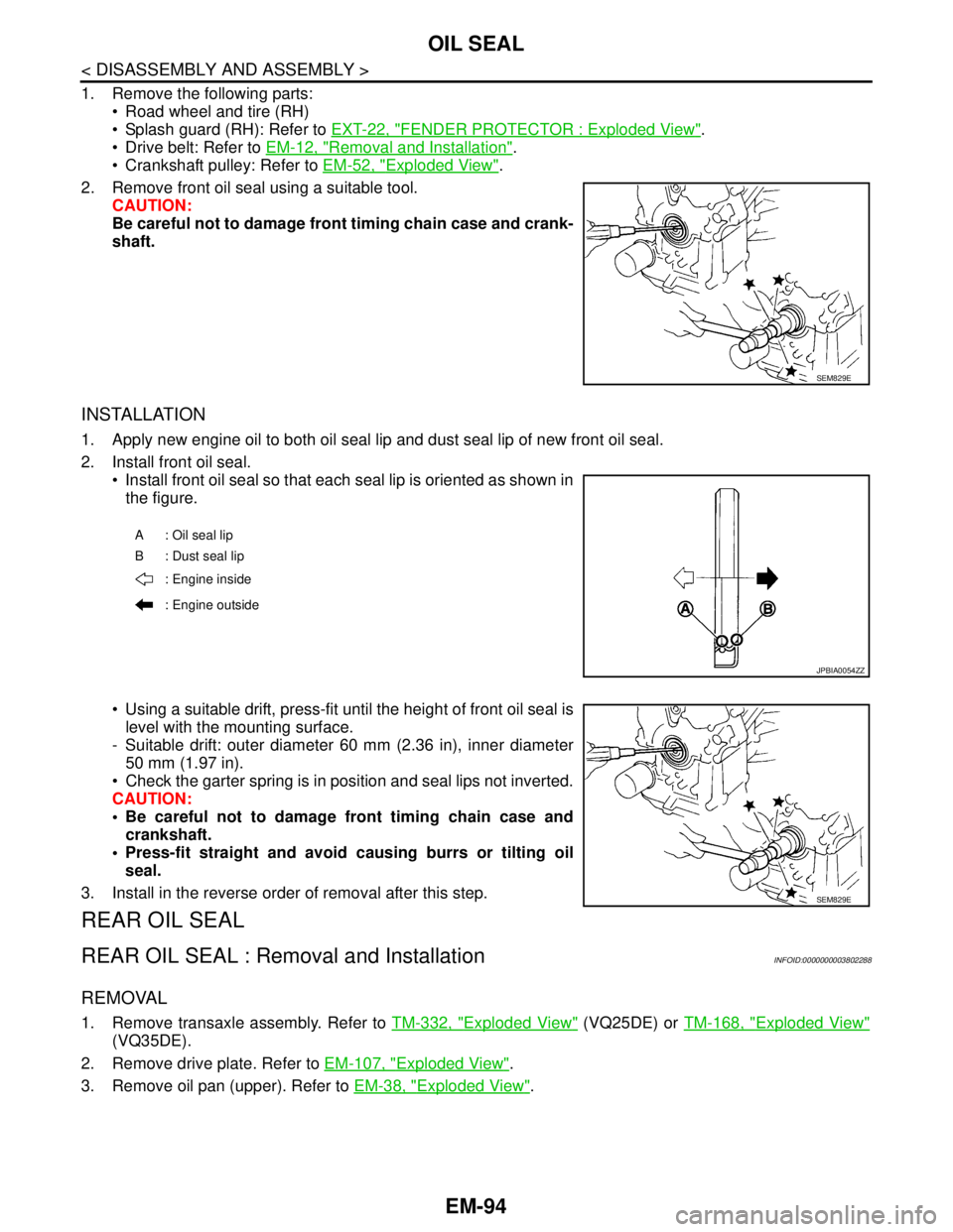
2. Remove front oil seal using a suitable tool.
CAUTION:
Be careful not to damage front timing chain case and crank-
shaft.
INSTALLATION
1. Apply new engine oil to both oil seal lip and dust seal lip of new front oil seal.
2. Install front oil seal.
Install front oil seal so that each seal lip is oriented as shown in
the figure.
Using a suitable drift, press-fit until the height of front oil seal is
level with the mounting surface.
- Suitable drift: outer diameter 60 mm (2.36 in), inner diameter
50 mm (1.97 in).
Check the garter spring is in position and seal lips not inverted.
CAUTION:
Be careful not to damage front timing chain case and
crankshaft.
Press-fit straight and avoid causing burrs or tilting oil
seal.
3. Install in the reverse order of removal after this step.
REAR OIL SEAL
REAR OIL SEAL : Removal and InstallationINFOID:0000000003802288
REMOVAL
1. Remove transaxle assembly. Refer to TM-332, "Exploded View" (VQ25DE) or TM-168, "Exploded View"
(VQ35DE).
2. Remove drive plate. Refer to EM-107, "
Exploded View".
3. Remove oil pan (upper). Refer to EM-38, "
Exploded View".
SEM829E
A: Oil seal lip
B : Dust seal lip
: Engine inside
: Engine outside
JPBIA0054ZZ
SEM829E
Page 1970 of 5121
OIL SEAL
EM-95
< DISASSEMBLY AND ASSEMBLY >
C
D
E
F
G
H
I
J
K
L
MA
EM
N
P O
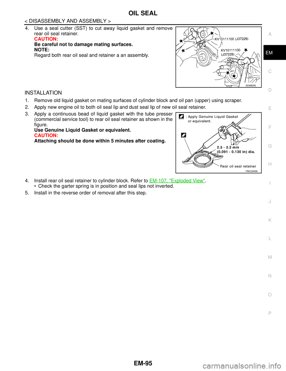
4. Use a seal cutter (SST) to cut away liquid gasket and remove
rear oil seal retainer.
CAUTION:
Be careful not to damage mating surfaces.
NOTE:
Regard both rear oil seal and retainer a an assembly.
INSTALLATION
1. Remove old liquid gasket on mating surfaces of cylinder block and oil pan (upper) using scraper.
2. Apply new engine oil to both oil seal lip and dust seal lip of new oil seal retainer.
3. Apply a continuous bead of liquid gasket with the tube presser
(commercial service tool) to rear oil seal retainer as shown in the
figure.
Use Genuine Liquid Gasket or equivalent.
CAUTION:
Attaching should be done within 5 minutes after coating.
4. Install rear oil seal retainer to cylinder block. Refer to EM-107, "
Exploded View".
Check the garter spring is in position and seal lips not inverted.
5. Install in the reverse order of removal after this step.
SEM830E
PBIC2649E
Page 1974 of 5121
CYLINDER HEAD
EM-99
< DISASSEMBLY AND ASSEMBLY >
C
D
E
F
G
H
I
J
K
L
MA
EM
N
P O
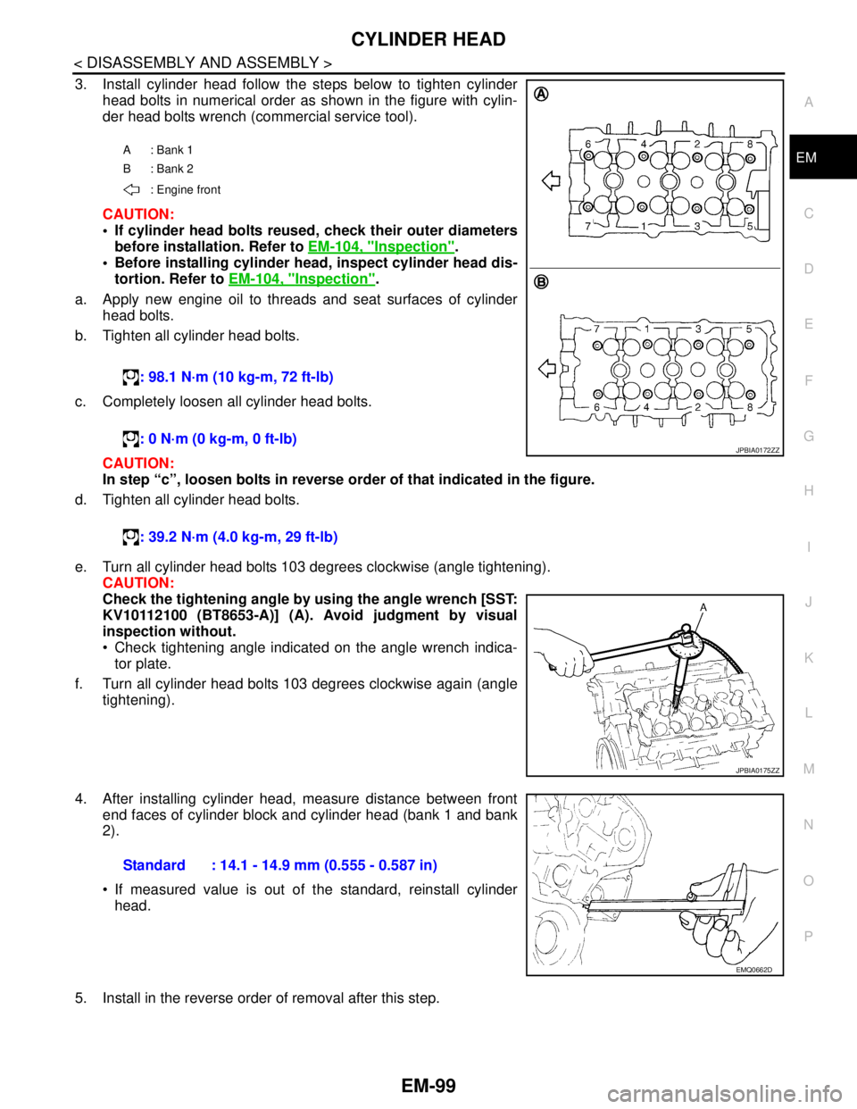
3. Install cylinder head follow the steps below to tighten cylinder
head bolts in numerical order as shown in the figure with cylin-
der head bolts wrench (commercial service tool).
CAUTION:
If cylinder head bolts reused, check their outer diameters
before installation. Refer to EM-104, "
Inspection".
Before installing cylinder head, inspect cylinder head dis-
tortion. Refer to EM-104, "
Inspection".
a. Apply new engine oil to threads and seat surfaces of cylinder
head bolts.
b. Tighten all cylinder head bolts.
c. Completely loosen all cylinder head bolts.
CAUTION:
In step “c”, loosen bolts in reverse order of that indicated in the figure.
d. Tighten all cylinder head bolts.
e. Turn all cylinder head bolts 103 degrees clockwise (angle tightening).
CAUTION:
Check the tightening angle by using the angle wrench [SST:
KV10112100 (BT8653-A)] (A). Avoid judgment by visual
inspection without.
Check tightening angle indicated on the angle wrench indica-
tor plate.
f. Turn all cylinder head bolts 103 degrees clockwise again (angle
tightening).
4. After installing cylinder head, measure distance between front
end faces of cylinder block and cylinder head (bank 1 and bank
2).
If measured value is out of the standard, reinstall cylinder
head.
5. Install in the reverse order of removal after this step.
A: Bank 1
B: Bank 2
: Engine front
: 98.1 N·m (10 kg-m, 72 ft-lb)
: 0 N·m (0 kg-m, 0 ft-lb)
: 39.2 N·m (4.0 kg-m, 29 ft-lb)
JPBIA0172ZZ
JPBIA0175ZZ
Standard : 14.1 - 14.9 mm (0.555 - 0.587 in)
EMQ0662D