2008 NISSAN TEANA check oil
[x] Cancel search: check oilPage 1888 of 5121
DRIVE BELT
EM-13
< ON-VEHICLE MAINTENANCE >
C
D
E
F
G
H
I
J
K
L
MA
EM
N
P O
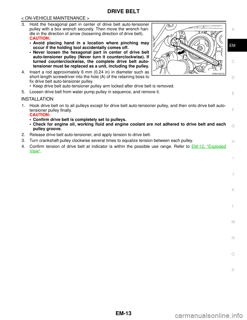
3. Hold the hexagonal part in center of drive belt auto-tensioner
pulley with a box wrench securely. Then move the wrench han-
dle in the direction of arrow (loosening direction of drive belt).
CAUTION:
Avoid placing hand in a location where pinching may
occur if the holding tool accidentally comes off.
Never loosen the hexagonal part in center of drive belt
auto-tensioner pulley (Never turn it counterclockwise). If
turned counterclockwise, the complete drive belt auto-
tensioner must be replaced as a unit, including the pulley.
4. Insert a rod approximately 6 mm (0.24 in) in diameter such as
short-length screwdriver into the hole (A) of the retaining boss to
fix drive belt auto-tensioner pulley.
Keep drive belt auto-tensioner pulley arm locked after drive belt is removed.
5. Loosen drive belt from water pump pulley in sequence, and remove it.
INSTALLATION
1. Hook drive belt on to all pulleys except for drive belt auto-tensioner pulley, and then onto drive belt auto-
tensioner pulley finally.
CAUTION:
Confirm drive belt is completely set to pulleys.
Check for engine oil, working fluid and engine coolant are not adhered to drive belt and each
pulley groove.
2. Release drive belt auto-tensioner, and apply tension to drive belt.
3. Turn crankshaft pulley clockwise several times to equalize tension between each pulley.
4. Confirm tension of drive belt at indicator is within the possible use range. Refer to EM-12, "
Exploded
View".
JPBIA1627ZZ
Page 1897 of 5121
EM-22
< ON-VEHICLE MAINTENANCE >
COMPRESSION PRESSURE
COMPRESSION PRESSURE
InspectionINFOID:0000000003802245
1. Warm up engine thoroughly. Then, stop it.
2. Release fuel pressure. Refer to EC-411, "
Inspection".
3. Disconnect fuel pump fuse to avoid fuel injection during measurement. Refer to EC-20,
"ComponentPartsLocation".
4. Remove engine cover. Refer to EM-24, "
Exploded View".
5. Remove ignition coil and spark plug from each cylinder. Refer to EM-49, "
Exploded View".
6. Connect engine tachometer (not required in use of CONSULT-III).
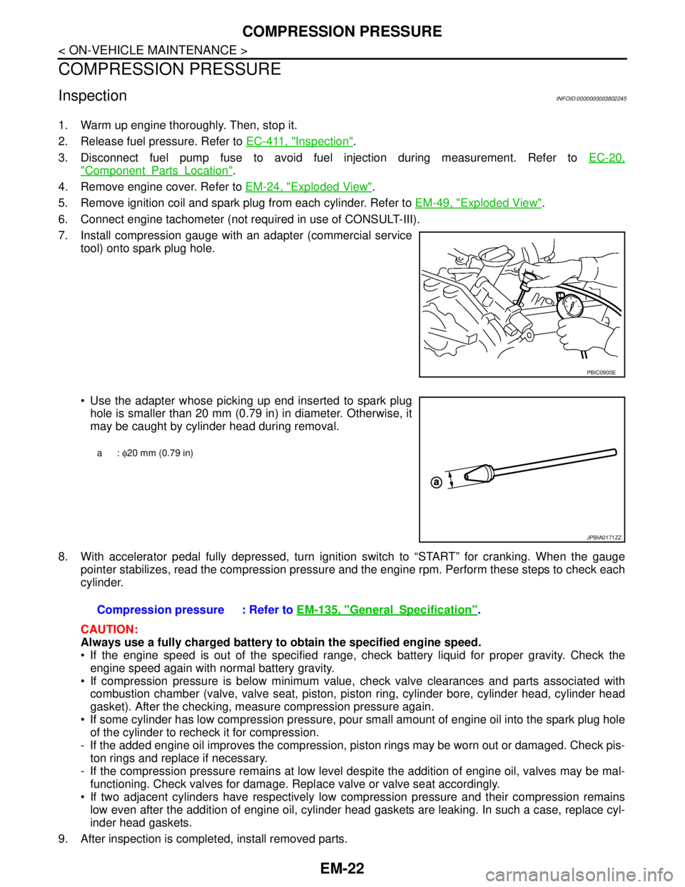
7. Install compression gauge with an adapter (commercial service
tool) onto spark plug hole.
Use the adapter whose picking up end inserted to spark plug
hole is smaller than 20 mm (0.79 in) in diameter. Otherwise, it
may be caught by cylinder head during removal.
8. With accelerator pedal fully depressed, turn ignition switch to “START” for cranking. When the gauge
pointer stabilizes, read the compression pressure and the engine rpm. Perform these steps to check each
cylinder.
CAUTION:
Always use a fully charged battery to obtain the specified engine speed.
If the engine speed is out of the specified range, check battery liquid for proper gravity. Check the
engine speed again with normal battery gravity.
If compression pressure is below minimum value, check valve clearances and parts associated with
combustion chamber (valve, valve seat, piston, piston ring, cylinder bore, cylinder head, cylinder head
gasket). After the checking, measure compression pressure again.
If some cylinder has low compression pressure, pour small amount of engine oil into the spark plug hole
of the cylinder to recheck it for compression.
- If the added engine oil improves the compression, piston rings may be worn out or damaged. Check pis-
ton rings and replace if necessary.
- If the compression pressure remains at low level despite the addition of engine oil, valves may be mal-
functioning. Check valves for damage. Replace valve or valve seat accordingly.
If two adjacent cylinders have respectively low compression pressure and their compression remains
low even after the addition of engine oil, cylinder head gaskets are leaking. In such a case, replace cyl-
inder head gaskets.
9. After inspection is completed, install removed parts.
PBIC0900E
a: φ20 mm (0.79 in)
JPBIA0171ZZ
Compression pressure : Refer to EM-135, "GeneralSpecification".
Page 1917 of 5121
EM-42
< ON-VEHICLE REPAIR >
OIL PAN AND OIL STRAINER
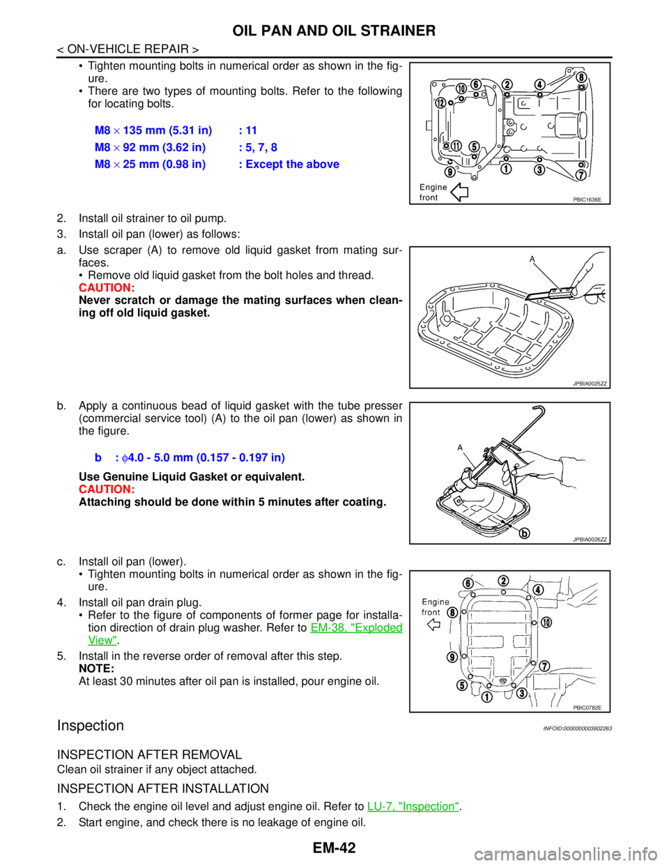
Tighten mounting bolts in numerical order as shown in the fig-
ure.
There are two types of mounting bolts. Refer to the following
for locating bolts.
2. Install oil strainer to oil pump.
3. Install oil pan (lower) as follows:
a. Use scraper (A) to remove old liquid gasket from mating sur-
faces.
Remove old liquid gasket from the bolt holes and thread.
CAUTION:
Never scratch or damage the mating surfaces when clean-
ing off old liquid gasket.
b. Apply a continuous bead of liquid gasket with the tube presser
(commercial service tool) (A) to the oil pan (lower) as shown in
the figure.
Use Genuine Liquid Gasket or equivalent.
CAUTION:
Attaching should be done within 5 minutes after coating.
c. Install oil pan (lower).
Tighten mounting bolts in numerical order as shown in the fig-
ure.
4. Install oil pan drain plug.
Refer to the figure of components of former page for installa-
tion direction of drain plug washer. Refer to EM-38, "
Exploded
View".
5. Install in the reverse order of removal after this step.
NOTE:
At least 30 minutes after oil pan is installed, pour engine oil.
InspectionINFOID:0000000003802263
INSPECTION AFTER REMOVAL
Clean oil strainer if any object attached.
INSPECTION AFTER INSTALLATION
1. Check the engine oil level and adjust engine oil. Refer to LU-7, "Inspection".
2. Start engine, and check there is no leakage of engine oil.M8 × 135 mm (5.31 in) : 11
M8 × 92 mm (3.62 in) : 5, 7, 8
M8 × 25 mm (0.98 in) : Except the above
PBIC1636E
JPBIA0025ZZ
b: φ4.0 - 5.0 mm (0.157 - 0.197 in)
JPBIA0026ZZ
PBIC0782E
Page 1918 of 5121
OIL PAN AND OIL STRAINER
EM-43
< ON-VEHICLE REPAIR >
C
D
E
F
G
H
I
J
K
L
MA
EM
N
P O
3. Stop engine and wait for 10 minutes.
4. Check the engine oil level again. Refer to LU-7, "
Inspection".
Page 1921 of 5121
EM-46
< ON-VEHICLE REPAIR >
FUEL INJECTOR AND FUEL TUBE
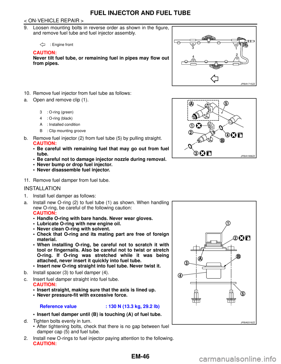
9. Loosen mounting bolts in reverse order as shown in the figure,
and remove fuel tube and fuel injector assembly.
CAUTION:
Never tilt fuel tube, or remaining fuel in pipes may flow out
from pipes.
10. Remove fuel injector from fuel tube as follows:
a. Open and remove clip (1).
b. Remove fuel injector (2) from fuel tube (5) by pulling straight.
CAUTION:
Be careful with remaining fuel that may go out from fuel
tube.
Be careful not to damage injector nozzle during removal.
Never bump or drop fuel injector.
Never disassemble fuel injector.
11. Remove fuel damper from fuel tube.
INSTALLATION
1. Install fuel damper as follows:
a. Install new O-ring (2) to fuel tube (1) as shown. When handling
new O-ring, be careful of the following caution:
CAUTION:
Handle O-ring with bare hands. Never wear gloves.
Lubricate O-ring with new engine oil.
Never clean O-ring with solvent.
Check that O-ring and its mating part are free of foreign
material.
When installing O-ring, be careful not to scratch it with
tool or fingernails. Also be careful not to twist or stretch
O-ring. If O-ring was stretched while it was being
attached, never insert it quickly into fuel tube.
Insert new O-ring straight into fuel tube. Never twist it.
b. Install spacer (3) to fuel damper (4).
c. Insert fuel damper straight into fuel tube.
CAUTION:
Insert straight, making sure that the axis is lined up.
Never pressure-fit with excessive force.
Insert fuel damper until (B) is touching (A) of fuel tube.
d. Tighten bolts evenly in turn.
After tightening bolts, check that there is no gap between fuel
damper cap (5) and fuel tube.
2. Install new O-rings to fuel injector paying attention to the following.
CAUTION:
: Engine front
JPBIA1715ZZ
3 : O-ring (green)
4 : O-ring (black)
A : Installed condition
B : Clip mounting groove
JPBIA1958ZZ
Reference value : 130 N (13.3 kg, 29.2 lb)
JPBIA0316ZZ
Page 1922 of 5121
FUEL INJECTOR AND FUEL TUBE
EM-47
< ON-VEHICLE REPAIR >
C
D
E
F
G
H
I
J
K
L
MA
EM
N
P O
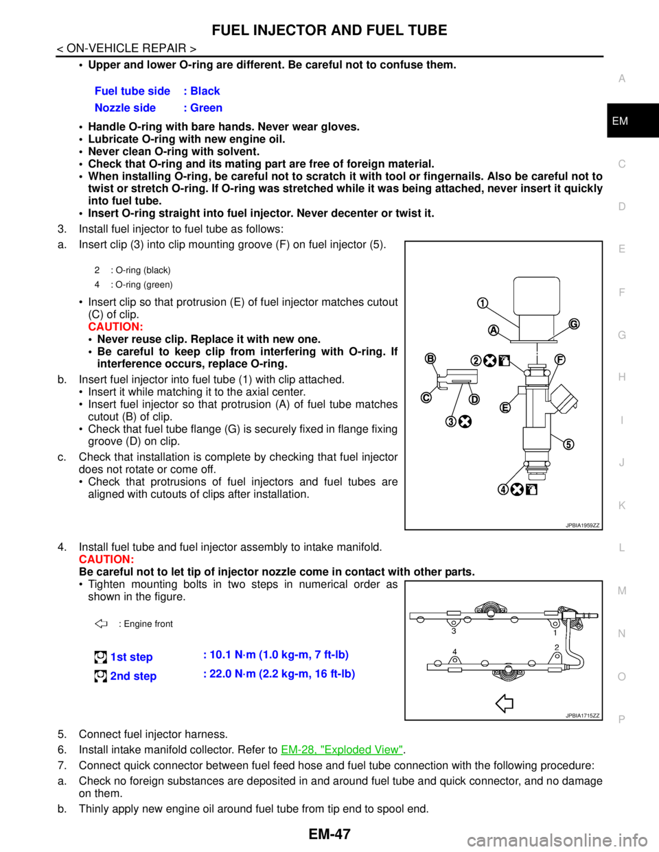
Upper and lower O-ring are different. Be careful not to confuse them.
Handle O-ring with bare hands. Never wear gloves.
Lubricate O-ring with new engine oil.
Never clean O-ring with solvent.
Check that O-ring and its mating part are free of foreign material.
When installing O-ring, be careful not to scratch it with tool or fingernails. Also be careful not to
twist or stretch O-ring. If O-ring was stretched while it was being attached, never insert it quickly
into fuel tube.
Insert O-ring straight into fuel injector. Never decenter or twist it.
3. Install fuel injector to fuel tube as follows:
a. Insert clip (3) into clip mounting groove (F) on fuel injector (5).
Insert clip so that protrusion (E) of fuel injector matches cutout
(C) of clip.
CAUTION:
Never reuse clip. Replace it with new one.
Be careful to keep clip from interfering with O-ring. If
interference occurs, replace O-ring.
b. Insert fuel injector into fuel tube (1) with clip attached.
Insert it while matching it to the axial center.
Insert fuel injector so that protrusion (A) of fuel tube matches
cutout (B) of clip.
Check that fuel tube flange (G) is securely fixed in flange fixing
groove (D) on clip.
c. Check that installation is complete by checking that fuel injector
does not rotate or come off.
Check that protrusions of fuel injectors and fuel tubes are
aligned with cutouts of clips after installation.
4. Install fuel tube and fuel injector assembly to intake manifold.
CAUTION:
Be careful not to let tip of injector nozzle come in contact with other parts.
Tighten mounting bolts in two steps in numerical order as
shown in the figure.
5. Connect fuel injector harness.
6. Install intake manifold collector. Refer to EM-28, "
Exploded View".
7. Connect quick connector between fuel feed hose and fuel tube connection with the following procedure:
a. Check no foreign substances are deposited in and around fuel tube and quick connector, and no damage
on them.
b. Thinly apply new engine oil around fuel tube from tip end to spool end.Fuel tube side : Black
Nozzle side : Green
2 : O-ring (black)
4 : O-ring (green)
JPBIA1959ZZ
: Engine front
1st step: 10.1 N·m (1.0 kg-m, 7 ft-lb)
2nd step: 22.0 N·m (2.2 kg-m, 16 ft-lb)
JPBIA1715ZZ
Page 1926 of 5121
IGNITION COIL, SPARK PLUG AND ROCKER COVER
EM-51
< ON-VEHICLE REPAIR >
C
D
E
F
G
H
I
J
K
L
MA
EM
N
P O
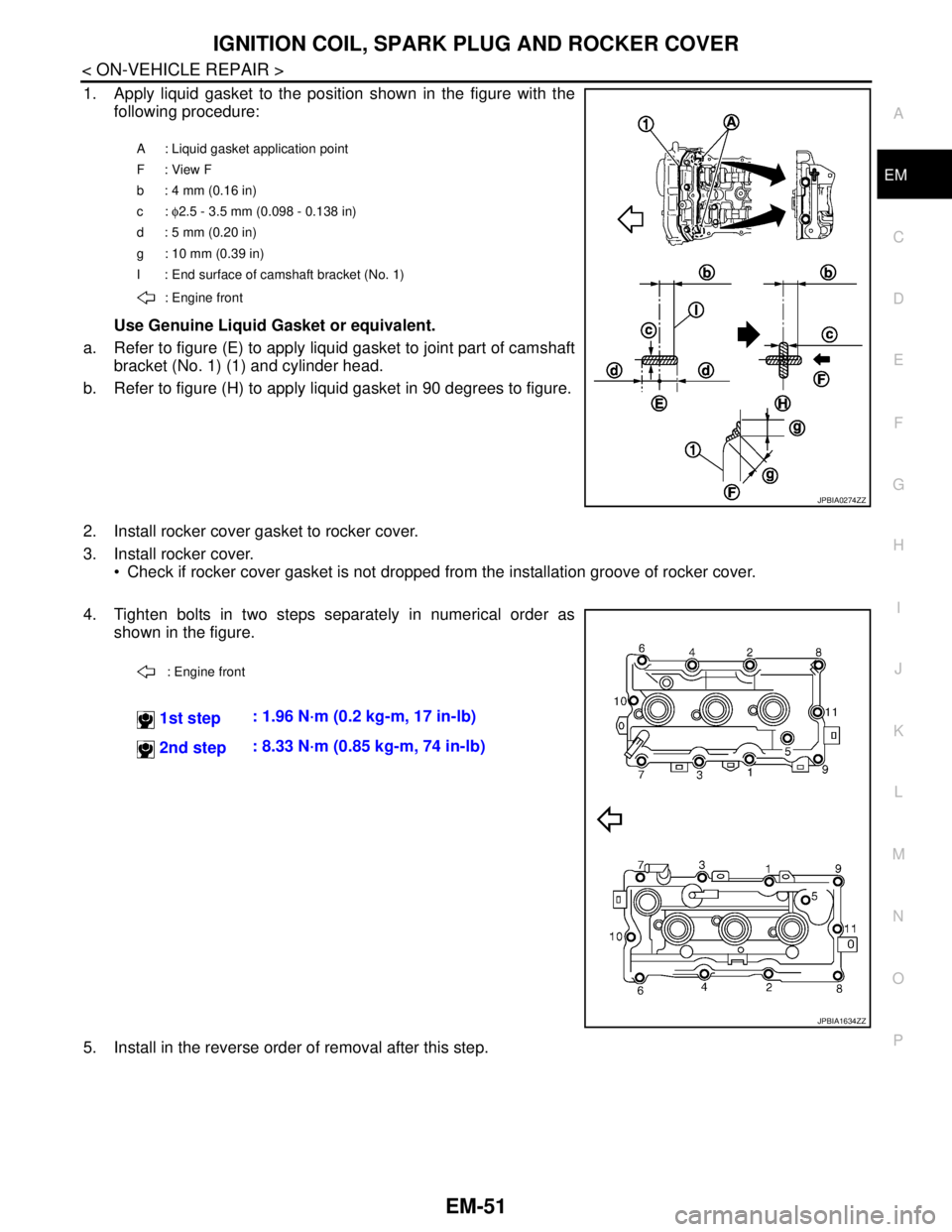
1. Apply liquid gasket to the position shown in the figure with the
following procedure:
Use Genuine Liquid Gasket or equivalent.
a. Refer to figure (E) to apply liquid gasket to joint part of camshaft
bracket (No. 1) (1) and cylinder head.
b. Refer to figure (H) to apply liquid gasket in 90 degrees to figure.
2. Install rocker cover gasket to rocker cover.
3. Install rocker cover.
Check if rocker cover gasket is not dropped from the installation groove of rocker cover.
4. Tighten bolts in two steps separately in numerical order as
shown in the figure.
5. Install in the reverse order of removal after this step.
A : Liquid gasket application point
F: View F
b: 4 mm (0.16 in)
c: φ2.5 - 3.5 mm (0.098 - 0.138 in)
d: 5 mm (0.20 in)
g : 10 mm (0.39 in)
I : End surface of camshaft bracket (No. 1)
: Engine front
JPBIA0274ZZ
: Engine front
1st step: 1.96 N·m (0.2 kg-m, 17 in-lb)
2nd step: 8.33 N·m (0.85 kg-m, 74 in-lb)
JPBIA1634ZZ
Page 1937 of 5121
EM-62
< ON-VEHICLE REPAIR >
TIMING CHAIN
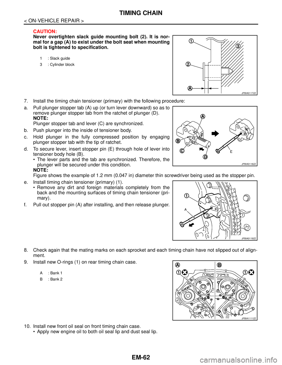
CAUTION:
Never overtighten slack guide mounting bolt (2). It is nor-
mal for a gap (A) to exist under the bolt seat when mounting
bolt is tightened to specification.
7. Install the timing chain tensioner (primary) with the following procedure:
a. Pull plunger stopper tab (A) up (or turn lever downward) so as to
remove plunger stopper tab from the ratchet of plunger (D).
NOTE:
Plunger stopper tab and lever (C) are synchronized.
b. Push plunger into the inside of tensioner body.
c. Hold plunger in the fully compressed position by engaging
plunger stopper tab with the tip of ratchet.
d. To secure lever, insert stopper pin (E) through hole of lever into
tensioner body hole (B).
The lever parts and the tab are synchronized. Therefore, the
plunger will be secured under this condition.
NOTE:
Figure shows the example of 1.2 mm (0.047 in) diameter thin screwdriver being used as the stopper pin.
e. Install timing chain tensioner (primary) (1).
Remove any dirt and foreign materials completely from the
back and the mounting surfaces of timing chain tensioner (pri-
mary).
f. Pull out stopper pin (A) after installing, and then release plunger.
8. Check again that the mating marks on each sprocket and each timing chain have not slipped out of align-
ment.
9. Install new O-rings (1) on rear timing chain case.
10. Install new front oil seal on front timing chain case.
Apply new engine oil to both oil seal lip and dust seal lip.
1 : Slack guide
3 : Cylinder block
JPBIA0117ZZ
JPBIA0118ZZ
JPBIA0119ZZ
A: Bank 1
B: Bank 2
JPBIA1111ZZ