Page 2612 of 5121

LOW-PRESSURE PIPE
HA-43
< ON-VEHICLE REPAIR >
C
D
E
F
G
H
J
K
L
MA
B
HA
N
O
P
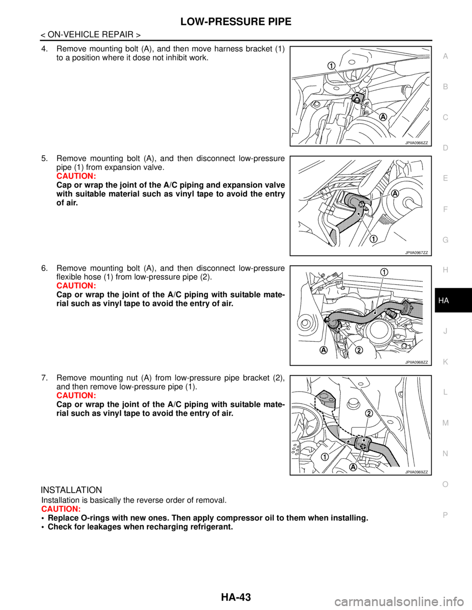
4. Remove mounting bolt (A), and then move harness bracket (1)
to a position where it dose not inhibit work.
5. Remove mounting bolt (A), and then disconnect low-pressure
pipe (1) from expansion valve.
CAUTION:
Cap or wrap the joint of the A/C piping and expansion valve
with suitable material such as vinyl tape to avoid the entry
of air.
6. Remove mounting bolt (A), and then disconnect low-pressure
flexible hose (1) from low-pressure pipe (2).
CAUTION:
Cap or wrap the joint of the A/C piping with suitable mate-
rial such as vinyl tape to avoid the entry of air.
7. Remove mounting nut (A) from low-pressure pipe bracket (2),
and then remove low-pressure pipe (1).
CAUTION:
Cap or wrap the joint of the A/C piping with suitable mate-
rial such as vinyl tape to avoid the entry of air.
INSTALLATION
Installation is basically the reverse order of removal.
CAUTION:
Replace O-rings with new ones. Then apply compressor oil to them when installing.
Check for leakages when recharging refrigerant.
JPIIA0966ZZ
JPIIA0967ZZ
JPIIA0968ZZ
JPIIA0969ZZ
Page 2614 of 5121
HIGH-PRESSURE PIPE
HA-45
< ON-VEHICLE REPAIR >
C
D
E
F
G
H
J
K
L
MA
B
HA
N
O
P
3. Remove mounting bolt (A), and then disconnect high-pressure
flexible hose (1) and high-pressure pipe (2) from condenser pipe
assembly.
CAUTION:
Cap or wrap the joint of the A/C piping with suitable mate-
rial such as vinyl tape to avoid the entry of air.
4. Remove reservoir tank. refer to CO-13, "
Exploded View".
5. Remove mounting clips (A), and then remove high-pressure pipe (1).
INSTALLATION
Installation is basically the reverse order of removal.
CAUTION:
Replace O-rings with new ones. Then apply compressor oil to them when installing.
Check for leakages when recharging refrigerant.
JPIIA0979ZZ
JPIIA0974ZZ
Page 2616 of 5121
CONDENSER
HA-47
< ON-VEHICLE REPAIR >
C
D
E
F
G
H
J
K
L
MA
B
HA
N
O
P
5. Disengage tabs (A).
6. Pull condenser (1) upward of vehicle, and then remove con-
denser (as shown in the figure).
CAUTION:
Be careful not to damage core surface of condenser.
INSTALLATION
Installation is basically the reverse order of removal.
CAUTION:
Replace O-rings with new ones. Then apply compressor oil to them when installing.
Check for leakages when recharging refrigerant.
JPIIA0983ZZ
Page 2618 of 5121
CONDENSER PIPE ASSEMBLY
HA-49
< ON-VEHICLE REPAIR >
C
D
E
F
G
H
J
K
L
MA
B
HA
N
O
P
Installation is basically the reverse order of removal.
CAUTION:
Replace O-rings with new ones. Then apply compressor oil to them when installing.
Check for leakages when recharging refrigerant.
Page 2619 of 5121

HA-50
< ON-VEHICLE REPAIR >
LIQUID TANK
LIQUID TANK
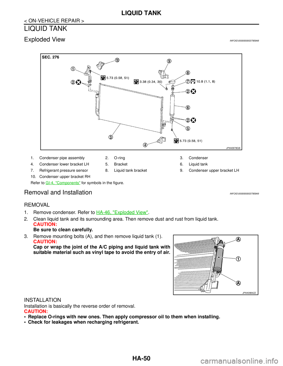
Exploded ViewINFOID:0000000003795848
Removal and InstallationINFOID:0000000003795849
REMOVAL
1. Remove condenser. Refer to HA-46, "Exploded View".
2. Clean liquid tank and its surrounding area. Then remove dust and rust from liquid tank.
CAUTION:
Be sure to clean carefully.
3. Remove mounting bolts (A), and then remove liquid tank (1).
CAUTION:
Cap or wrap the joint of the A/C piping and liquid tank with
suitable material such as vinyl tape to avoid the entry of air.
INSTALLATION
Installation is basically the reverse order of removal.
CAUTION:
Replace O-rings with new ones. Then apply compressor oil to them when installing.
Check for leakages when recharging refrigerant.
1. Condenser pipe assembly 2. O-ring 3. Condenser
4. Condenser lower bracket LH 5. Bracket 6. Liquid tank
7. Refrigerant pressure sensor 8. Liquid tank bracket 9. Condenser upper bracket LH
10. Condenser upper bracket RH
Refer to GI-4, "
Components" for symbols in the figure.
JPIIA0978GB
JPIIA0984ZZ
Page 2620 of 5121
REFRIGERANT PRESSURE SENSOR
HA-51
< ON-VEHICLE REPAIR >
C
D
E
F
G
H
J
K
L
MA
B
HA
N
O
P
REFRIGERANT PRESSURE SENSOR
Exploded ViewINFOID:0000000003795850
Removal and InstallationINFOID:0000000003795851
REMOVAL
1. Remove liquid tank. Refer to HA-50, "Exploded View".
2. Fix the liquid tank (1) with a vise (A). Remove the refrigerant
pressure sensor (2) with a wrench (B).
CAUTION:
Be careful not to damage liquid tank.
INSTALLATION
Installation is basically the reverse order of removal.
CAUTION:
Replace O-rings with new ones. Then apply compressor oil to them when installing.
Check for leakages when recharging refrigerant.
1. Condenser pipe assembly 2. O-ring 3. Condenser
4. Condenser lower bracket LH 5. Bracket 6. Liquid tank
7. Refrigerant pressure sensor 8. Liquid tank bracket 9. Condenser upper bracket LH
10. Condenser upper bracket RH
Refer to GI-4, "
Components" for symbols in the figure.
JPIIA0978GB
JSIIA0075ZZ
Page 2622 of 5121

EVAPORATOR
HA-53
< ON-VEHICLE REPAIR >
C
D
E
F
G
H
J
K
L
MA
B
HA
N
O
P
Removal and InstallationINFOID:0000000003795855
REMOVAL
1. Remove evaporator pipe assembly. Refer to HA-54, "Exploded View".
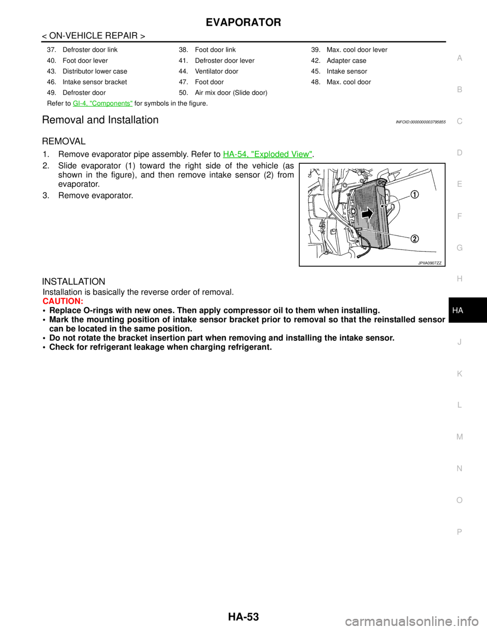
2. Slide evaporator (1) toward the right side of the vehicle (as
shown in the figure), and then remove intake sensor (2) from
evaporator.
3. Remove evaporator.
INSTALLATION
Installation is basically the reverse order of removal.
CAUTION:
Replace O-rings with new ones. Then apply compressor oil to them when installing.
Mark the mounting position of intake sensor bracket prior to removal so that the reinstalled sensor
can be located in the same position.
Do not rotate the bracket insertion part when removing and installing the intake sensor.
Check for refrigerant leakage when charging refrigerant.
37. Defroster door link 38. Foot door link 39. Max. cool door lever
40. Foot door lever 41. Defroster door lever 42. Adapter case
43. Distributor lower case 44. Ventilator door 45. Intake sensor
46. Intake sensor bracket 47. Foot door 48. Max. cool door
49. Defroster door 50. Air mix door (Slide door)
Refer to GI-4, "
Components" for symbols in the figure.
JPIIA0907ZZ
Page 2625 of 5121
HA-56
< ON-VEHICLE REPAIR >
EVAPORATOR PIPE ASSEMBLY
9. Remove mounting bolts (A), and then remove evaporator pipe
assembly (1) from expansion valve (2).
CAUTION:
Cap or wrap the joint of the A/C piping and expansion valve
with suitable material such as vinyl tape to avoid the entry
of air.
INSTALLATION
Installation is basically the reverse order of removal.
CAUTION:
Replace O-rings with new ones. Then apply compressor oil to them when installing.
Check for leakages when recharging refrigerant.
JPIIA0547ZZ