2008 NISSAN TEANA check oil
[x] Cancel search: check oilPage 3215 of 5121
CHASSIS MAINTENANCE
MA-27
< ON-VEHICLE MAINTENANCE >
C
D
E
F
G
H
I
J
K
L
MB
MAN
OA
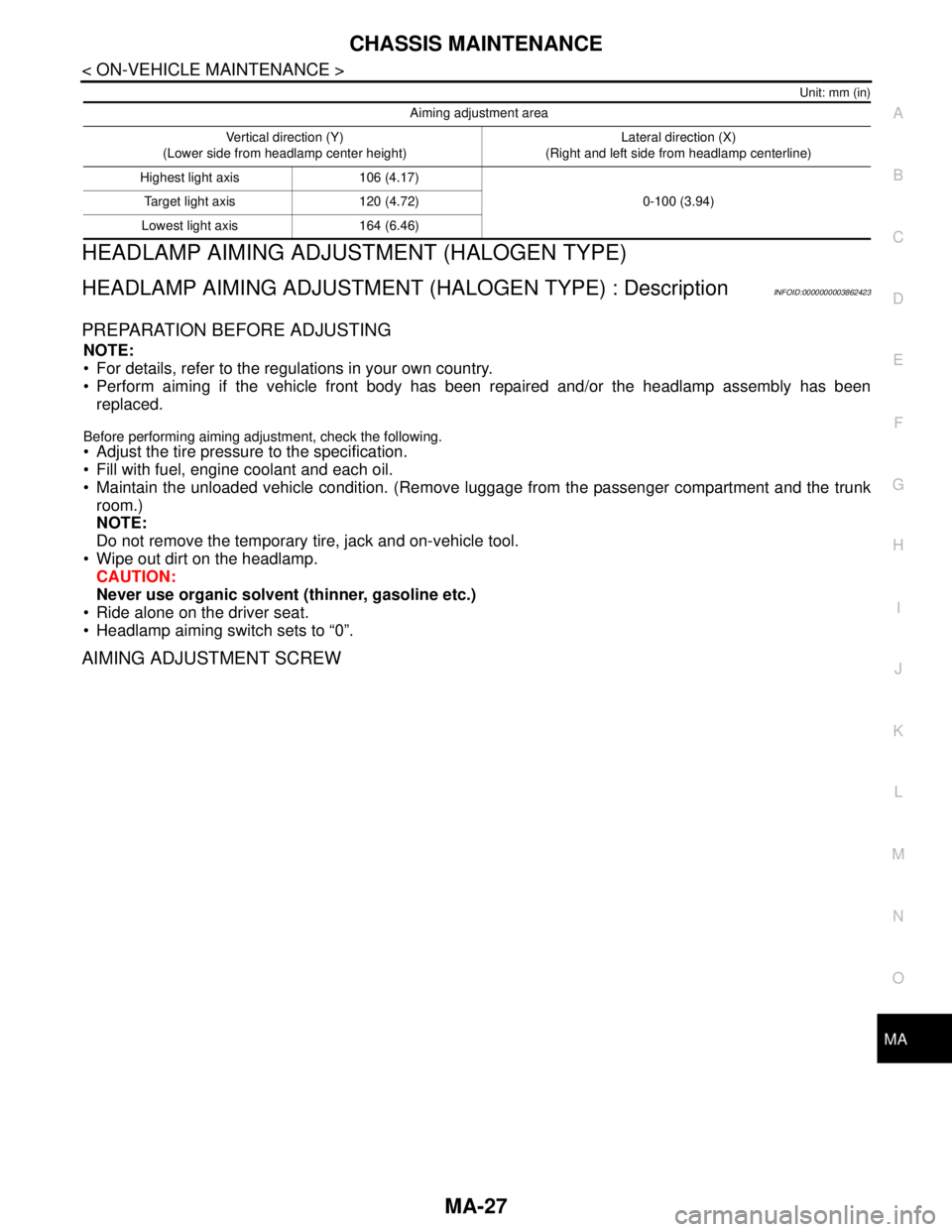
Unit: mm (in)
HEADLAMP AIMING ADJUSTMENT (HALOGEN TYPE)
HEADLAMP AIMING ADJUSTMENT (HALOGEN TYPE) : DescriptionINFOID:0000000003862423
PREPARATION BEFORE ADJUSTING
NOTE:
For details, refer to the regulations in your own country.
Perform aiming if the vehicle front body has been repaired and/or the headlamp assembly has been
replaced.
Before performing aiming adjustment, check the following.
Adjust the tire pressure to the specification.
Fill with fuel, engine coolant and each oil.
Maintain the unloaded vehicle condition. (Remove luggage from the passenger compartment and the trunk
room.)
NOTE:
Do not remove the temporary tire, jack and on-vehicle tool.
Wipe out dirt on the headlamp.
CAUTION:
Never use organic solvent (thinner, gasoline etc.)
Ride alone on the driver seat.
Headlamp aiming switch sets to “0”.
AIMING ADJUSTMENT SCREW
Aiming adjustment area
Vertical direction (Y)
(Lower side from headlamp center height)Lateral direction (X)
(Right and left side from headlamp centerline)
Highest light axis 106 (4.17)
0-100 (3.94) Target light axis 120 (4.72)
Lowest light axis 164 (6.46)
Page 3221 of 5121
CHASSIS MAINTENANCE
MA-33
< ON-VEHICLE MAINTENANCE >
C
D
E
F
G
H
I
J
K
L
MB
MAN
OA
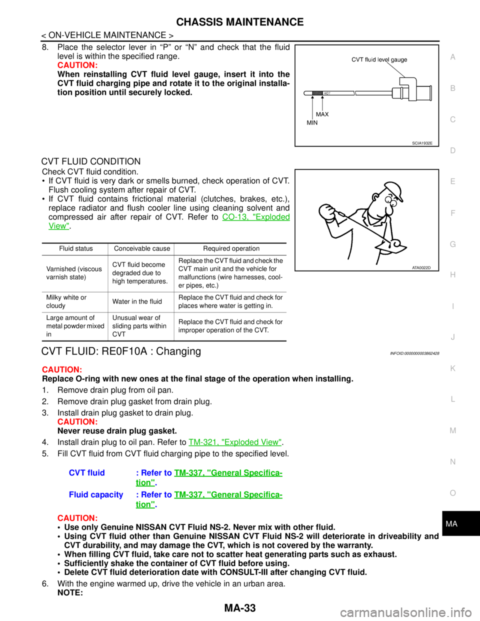
8. Place the selector lever in “P” or “N” and check that the fluid
level is within the specified range.
CAUTION:
When reinstalling CVT fluid level gauge, insert it into the
CVT fluid charging pipe and rotate it to the original installa-
tion position until securely locked.
CVT FLUID CONDITION
Check CVT fluid condition.
If CVT fluid is very dark or smells burned, check operation of CVT.
Flush cooling system after repair of CVT.
If CVT fluid contains frictional material (clutches, brakes, etc.),
replace radiator and flush cooler line using cleaning solvent and
compressed air after repair of CVT. Refer to CO-13, "
Exploded
View".
CVT FLUID: RE0F10A : ChangingINFOID:0000000003862428
CAUTION:
Replace O-ring with new ones at the final stage of the operation when installing.
1. Remove drain plug from oil pan.
2. Remove drain plug gasket from drain plug.
3. Install drain plug gasket to drain plug.
CAUTION:
Never reuse drain plug gasket.
4. Install drain plug to oil pan. Refer to TM-321, "
Exploded View".
5. Fill CVT fluid from CVT fluid charging pipe to the specified level.
CAUTION:
Use only Genuine NISSAN CVT Fluid NS-2. Never mix with other fluid.
Using CVT fluid other than Genuine NISSAN CVT Fluid NS-2 will deteriorate in driveability and
CVT durability, and may damage the CVT, which is not covered by the warranty.
When filling CVT fluid, take care not to scatter heat generating parts such as exhaust.
Sufficiently shake the container of CVT fluid before using.
Delete CVT fluid deterioration date with CONSULT-III after changing CVT fluid.
6. With the engine warmed up, drive the vehicle in an urban area.
NOTE:
SCIA1932E
Fluid status Conceivable cause Required operation
Varnished (viscous
varnish state)CVT fluid become
degraded due to
high temperatures.Replace the CVT fluid and check the
CVT main unit and the vehicle for
malfunctions (wire harnesses, cool-
er pipes, etc.)
Milky white or
cloudyWater in the fluidReplace the CVT fluid and check for
places where water is getting in.
Large amount of
metal powder mixed
inUnusual wear of
sliding parts within
CVTReplace the CVT fluid and check for
improper operation of the CVT.
ATA0022D
CVT fluid : Refer to TM-337, "General Specifica-
tion".
Fluid capacity : Refer to TM-337, "
General Specifica-
tion".
Page 3223 of 5121
CHASSIS MAINTENANCE
MA-35
< ON-VEHICLE MAINTENANCE >
C
D
E
F
G
H
I
J
K
L
MB
MAN
OA
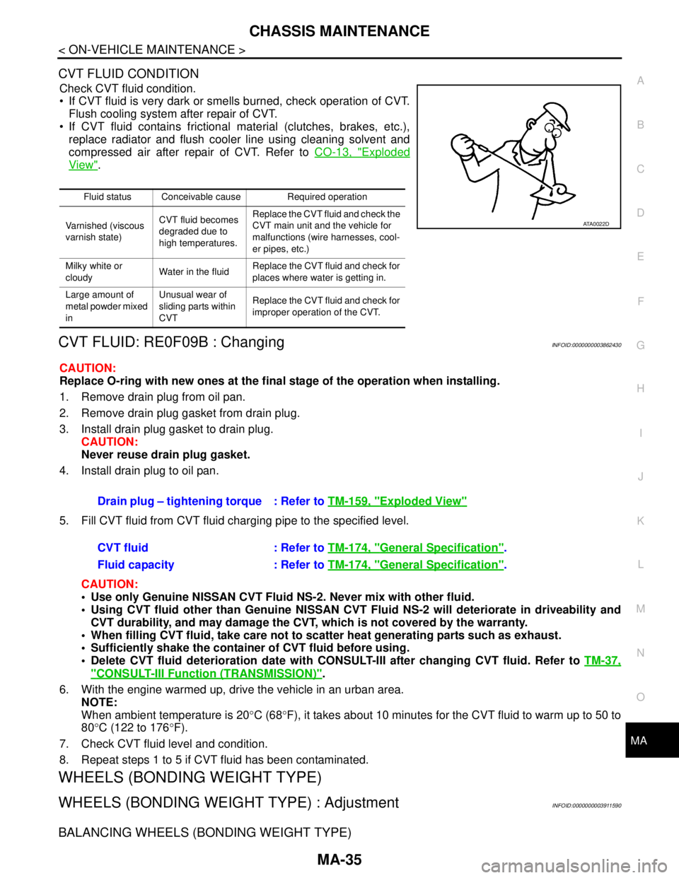
CVT FLUID CONDITION
Check CVT fluid condition.
If CVT fluid is very dark or smells burned, check operation of CVT.
Flush cooling system after repair of CVT.
If CVT fluid contains frictional material (clutches, brakes, etc.),
replace radiator and flush cooler line using cleaning solvent and
compressed air after repair of CVT. Refer to CO-13, "
Exploded
View".
CVT FLUID: RE0F09B : ChangingINFOID:0000000003862430
CAUTION:
Replace O-ring with new ones at the final stage of the operation when installing.
1. Remove drain plug from oil pan.
2. Remove drain plug gasket from drain plug.
3. Install drain plug gasket to drain plug.
CAUTION:
Never reuse drain plug gasket.
4. Install drain plug to oil pan.
5. Fill CVT fluid from CVT fluid charging pipe to the specified level.
CAUTION:
Use only Genuine NISSAN CVT Fluid NS-2. Never mix with other fluid.
Using CVT fluid other than Genuine NISSAN CVT Fluid NS-2 will deteriorate in driveability and
CVT durability, and may damage the CVT, which is not covered by the warranty.
When filling CVT fluid, take care not to scatter heat generating parts such as exhaust.
Sufficiently shake the container of CVT fluid before using.
Delete CVT fluid deterioration date with CONSULT-III after changing CVT fluid. Refer to TM-37,
"CONSULT-III Function (TRANSMISSION)".
6. With the engine warmed up, drive the vehicle in an urban area.
NOTE:
When ambient temperature is 20°C (68°F), it takes about 10 minutes for the CVT fluid to warm up to 50 to
80°C (122 to 176°F).
7. Check CVT fluid level and condition.
8. Repeat steps 1 to 5 if CVT fluid has been contaminated.
WHEELS (BONDING WEIGHT TYPE)
WHEELS (BONDING WEIGHT TYPE) : AdjustmentINFOID:0000000003911590
BALANCING WHEELS (BONDING WEIGHT TYPE)
Fluid status Conceivable cause Required operation
Varnished (viscous
varnish state)CVT fluid becomes
degraded due to
high temperatures.Replace the CVT fluid and check the
CVT main unit and the vehicle for
malfunctions (wire harnesses, cool-
er pipes, etc.)
Milky white or
cloudyWater in the fluidReplace the CVT fluid and check for
places where water is getting in.
Large amount of
metal powder mixed
inUnusual wear of
sliding parts within
CVTReplace the CVT fluid and check for
improper operation of the CVT.
ATA0022D
Drain plug – tightening torque : Refer to TM-159, "Exploded View"
CVT fluid : Refer to TM-174, "General Specification".
Fluid capacity : Refer to TM-174, "
General Specification".
Page 3228 of 5121
MA-40
< ON-VEHICLE MAINTENANCE >
CHASSIS MAINTENANCE
POWER STEERING FLUID AND LINES : Inspection
INFOID:0000000003862441
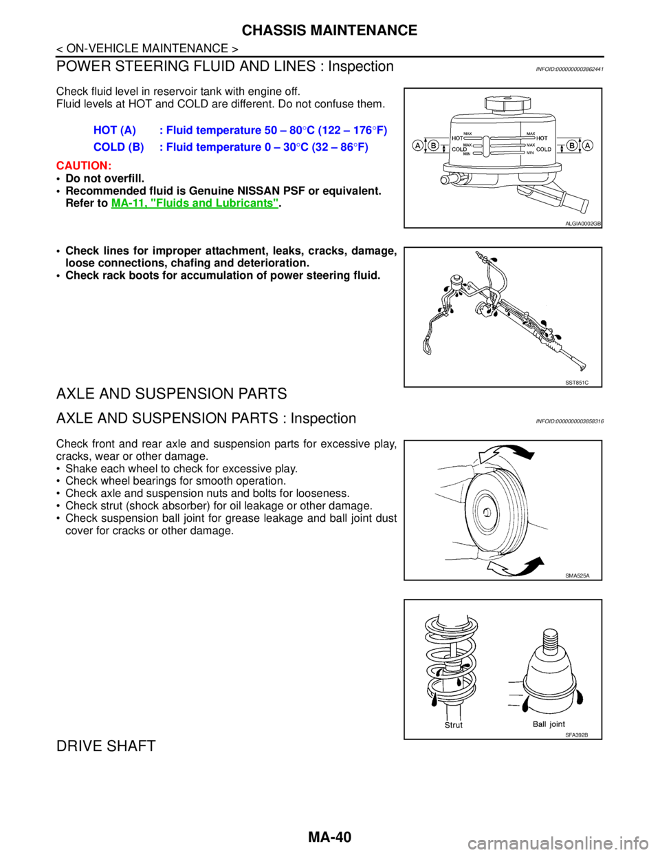
Check fluid level in reservoir tank with engine off.
Fluid levels at HOT and COLD are different. Do not confuse them.
CAUTION:
Do not overfill.
Recommended fluid is Genuine NISSAN PSF or equivalent.
Refer to MA-11, "
Fluids and Lubricants".
Check lines for improper attachment, leaks, cracks, damage,
loose connections, chafing and deterioration.
Check rack boots for accumulation of power steering fluid.
AXLE AND SUSPENSION PARTS
AXLE AND SUSPENSION PARTS : InspectionINFOID:0000000003858316
Check front and rear axle and suspension parts for excessive play,
cracks, wear or other damage.
Shake each wheel to check for excessive play.
Check wheel bearings for smooth operation.
Check axle and suspension nuts and bolts for looseness.
Check strut (shock absorber) for oil leakage or other damage.
Check suspension ball joint for grease leakage and ball joint dust
cover for cracks or other damage.
DRIVE SHAFT
HOT (A) : Fluid temperature 50 – 80°C (122 – 176°F)
COLD (B) : Fluid temperature 0 – 30°C (32 – 86°F)
ALGIA0002GB
SST851C
SMA525A
SFA392B
Page 3230 of 5121
MA-42
< ON-VEHICLE MAINTENANCE >
BODY MAINTENANCE
BODY MAINTENANCE
LOCKS, HINGES AND HOOD LATCH
LOCKS, HINGES AND HOOD LATCH : LubricatingINFOID:0000000003858318
For hood and hood lock illustration.
Hood: Refer to DLK-191, "
HOOD ASSEMBLY : Exploded View".
Hood lock control: Refer to DLK-220, "
Exploded View".
For door and door lock illustration.
Front door: Refer to DLK-201, "
DOOR ASSEMBLY : Exploded View".
Front door lock: Refer to DLK-222, "
DOOR LOCK : Exploded View".
Rear door: Refer to DLK-207, "
DOOR ASSEMBLY : Exploded View".
Rear door lock: Refer to DLK-227, "
DOOR LOCK : Exploded View".
For trunk lid and trunk lid lock illustration.
Trunk lid: Refer to DLK-213, "
TRUNK LID ASSEMBLY : Exploded View".
Trunk lid lock: Refer to DLK-231, "
Exploded View".
SEAT BELT, BUCKLES, RETRACTORS, ANCHORS AND ADJUSTERS
SEAT BELT, BUCKLES, RETRACTORS, ANCHORS AND ADJUSTERS : Inspection
INFOID:0000000003858319
For front seat belt illustration. Refer to SB-5, "SEAT BELT RETRACTOR : Exploded View".
For rear seat belt illustration. Refer to SB-10, "
SEAT BELT RETRACTOR : Exploded View".
CAUTION:
After any collision, inspect all seat belt assemblies, including retractors and other attached hard-
wares (I.e. anchor bolt, guide rail set). Nissan recommends to replace all seat belt assemblies in use
during a collision, unless not damaged and properly operating after minor collision.
Also inspect seat belt assemblies not in use during a collision, and replace if damaged or improperly
operating.
Seat belt pre-tensioner should be replaced even if the seat belts are not in use during a frontal colli-
sion where the driver and passenger air bags are deployed.
If any component of seat belt assembly is questionable, do not repair.
Replace as seat belt assembly.
If webbing is cut, frayed, or damaged, replace belt assembly.
Never oil tongue and buckle.
Use a genuine NISSAN seat belt assembly.
For details, refer to SB-3, "
SEAT BELT RETRACTOR : Inspection" , SB-8, "SEAT BELT RETRACTOR :
Inspection" in SB section.
Check anchors for loose mounting
Check belts for damage
Check retractor for smooth operation
Check function of buckles and tongues when buckled and released
BODY CORROSION
BODY CORROSION : Checking Body CorrosionINFOID:0000000003858320
Visually check body panels for collision damage (scratches, chipping, rubbing, etc.) or damage to the anti-cor-
rosion materials. In particular, check the following locations.
HEMMED PANELS
Hood front end, door lower end, trunk lid rear end, etc.
PA N E L J O I N T
Side sill of rear fender and center pillar, rear wheel housing of rear fender, around strut tower in engine com-
partment, etc.
PA N E L E D G E
Trunk lid opening, sunroof opening, fender wheel-arch flange, fuel filler lid flange, around holes in panel, etc.
PARTS CONTACT
Waist moulding, windshield moulding, bumper, etc.
Page 3256 of 5121

MWI-2
DIAGNOSIS SYSTEM (METER) .......................32
Diagnosis Description .............................................32
CONSULT-III Function (METER/M&A) ...................33
COMPONENT DIAGNOSIS ........................37
U1000 CAN COMM CIRCUIT ............................37
Description ..............................................................37
DTC Logic ...............................................................37
Diagnosis Procedure .............................................37
U1010 CONTROL UNIT (CAN) .........................38
Description ..............................................................38
DTC Logic ...............................................................38
Diagnosis Procedure ..............................................38
B2205 VEHICLE SPEED ...................................39
Description ..............................................................39
DTC Logic ...............................................................39
Diagnosis Procedure .............................................39
B2267 ENGINE SPEED .....................................40
Description ..............................................................40
DTC Logic ...............................................................40
Diagnosis Procedure ..............................................40
B2268 WATER TEMP ........................................41
Description ..............................................................41
DTC Logic ...............................................................41
Diagnosis Procedure ..............................................41
POWER SUPPLY AND GROUND CIRCUIT .....42
COMBINATION METER ...........................................42
COMBINATION METER : Diagnosis Procedure ....42
BCM (BODY CONTROL MODULE) .........................42
BCM (BODY CONTROL MODULE) : Diagnosis
Procedure ...............................................................
42
IPDM E/R (INTELLIGENT POWER DISTRIBU-
TION MODULE ENGINE ROOM) .............................
43
IPDM E/R (INTELLIGENT POWER DISTRIBU-
TION MODULE ENGINE ROOM) : Diagnosis Pro-
cedure .....................................................................
43
FUEL LEVEL SENSOR SIGNAL CIRCUIT .......45
Description ..............................................................45
Component Function Check ...................................45
Diagnosis Procedure .............................................45
Component Inspection ............................................46
METER CONTROL SWITCH SIGNAL CIR-
CUIT ...................................................................
48
Description ..............................................................48
Diagnosis Procedure ..............................................48
Component Inspection ............................................49
OIL PRESSURE SWITCH SIGNAL CIRCUIT ...50
Description ..............................................................50
Component Function Check ...................................50
Diagnosis Procedure ..............................................50
Component Inspection ............................................50
PARKING BRAKE SWITCH SIGNAL CIR-
CUIT ...................................................................
52
Description ..............................................................52
Diagnosis Procedure ...............................................52
Component Inspection ............................................52
ECU DIAGNOSIS .......................................53
COMBINATION METER ....................................53
Reference Value .....................................................53
Wiring Diagram - METER - .....................................59
Fail-Safe ..................................................................66
DTC Index ...............................................................67
BCM (BODY CONTROL MODULE) ..................68
Reference Value .....................................................68
Wiring Diagram - BCM - ..........................................91
Fail-safe ..................................................................97
DTC Inspection Priority Chart ...............................99
DTC Index ............................................................100
IPDM E/R (INTELLIGENT POWER DISTRI-
BUTION MODULE ENGINE ROOM) ................
102
Reference Value ...................................................102
Wiring Diagram - IPDM E/R - ................................110
Fail-safe ................................................................113
DTC Index ............................................................115
SYMPTOM DIAGNOSIS ...........................116
THE FUEL GAUGE POINTER DOES NOT
MOVE ................................................................
116
Description ............................................................116
Diagnosis Procedure .............................................116
THE METER CONTROL SWITCH IS INOPER-
ATIVE ................................................................
117
Description ............................................................117
Diagnosis Procedure .............................................117
THE OIL PRESSURE WARNING LAMP
DOES NOT TURN ON ......................................
118
Description ............................................................118
Diagnosis Procedure .............................................118
THE OIL PRESSURE WARNING LAMP
DOES NOT TURN OFF ....................................
119
Description ............................................................119
Diagnosis Procedure .............................................119
THE PARKING BRAKE RELEASE WARNING
CONTINUES DISPLAYING, OR DOES NOT
DISPLAY ...........................................................
120
Description ............................................................120
Diagnosis Procedure .............................................120
THE DOOR OPEN WARNING CONTINUES
DISPLAYING, OR DOES NOT DISPLAY ........
121
Description ............................................................121
Page 3260 of 5121
MWI-6
< FUNCTION DIAGNOSIS >
METER SYSTEM
FUNCTION DIAGNOSIS
METER SYSTEM
METER SYSTEM
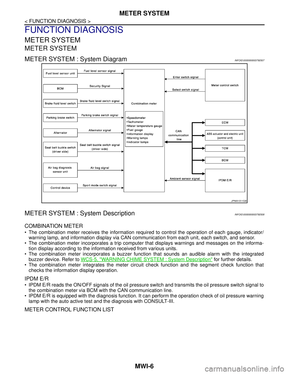
METER SYSTEM : System DiagramINFOID:0000000003792507
METER SYSTEM : System DescriptionINFOID:0000000003792508
COMBINATION METER
The combination meter receives the information required to control the operation of each gauge, indicator/
warning lamp, and information display via CAN communication from each unit, each switch, and sensor.
The combination meter incorporates a trip computer that displays warnings and messages on the informa-
tion display according to the information received from various units.
The combination meter incorporates a buzzer function that sounds an audible alarm with the integrated
buzzer device. Refer to WCS-5, "
WARNING CHIME SYSTEM : System Description" for further details.
The combination meter integrates the meter circuit check function and the segment check function that
checks the information display operation.
IPDM E/R
IPDM E/R reads the ON/OFF signals of the oil pressure switch and transmits the oil pressure switch signal to
the combination meter via BCM with the CAN communication line.
IPDM E/R is equipped with the diagnosis function. It can perform the operation check of oil pressure warning
lamp with the auto active test and the diagnosis with CONSULT-III.
METER CONTROL FUNCTION LIST
JPNIA1011GB
Page 3288 of 5121
![NISSAN TEANA 2008 Service Manual MWI-34
< FUNCTION DIAGNOSIS >
DIAGNOSIS SYSTEM (METER)
W TEMP METER
[°C] XValue of engine coolant temperature signal is received from ECM via CAN com-
munication.
NOTE:
215 is displayed when the mal NISSAN TEANA 2008 Service Manual MWI-34
< FUNCTION DIAGNOSIS >
DIAGNOSIS SYSTEM (METER)
W TEMP METER
[°C] XValue of engine coolant temperature signal is received from ECM via CAN com-
munication.
NOTE:
215 is displayed when the mal](/manual-img/5/57391/w960_57391-3287.png)
MWI-34
< FUNCTION DIAGNOSIS >
DIAGNOSIS SYSTEM (METER)
W TEMP METER
[°C] XValue of engine coolant temperature signal is received from ECM via CAN com-
munication.
NOTE:
215 is displayed when the malfunction signal is input.
ABS W/L
[On/Off]Status of ABS warning lamp detected from ABS warning lamp signal is received
from ABS actuator and electric unit (control unit) via CAN communication.
VDC/TCS IND
[On/Off]Status of VDC OFF indicator lamp detected from VDC OFF indicator lamp signal
is received from ABS actuator and electric unit (control unit) via CAN communica-
tion.
SLIP IND
[On/Off]Status of SLIP indicator lamp detected from slip indicator lamp signal received
from ABS actuator and electric unit (control unit) via CAN communication.
BRAKE W/L
[On/Off]Status of brake warning lamp detected from brake warning lamp signal is received
from ABS actuator and electric unit (control unit) via CAN communication.
NOTE:
Displays “Off” if the brake warning lamp is illuminated when the valve check starts,
the parking brake switch is turned ON or the brake fluid level switch is turned ON.
DOOR W/L
[On/Off]Status of door warning detected from door switch signal received from BCM via
CAN communication.
TRUNK/GLAS-H
[On/Off]Status of trunk warning detected from trunk switch signal received from BCM via
CAN communication.
HI-BEAM IND
[On/Off]Status of high beam indicator lamp detected from high beam request signal is re-
ceived from BCM via CAN communication.
TURN IND
[On/Off]Status of turn indicator lamp detected from turn indicator signal is received from
BCM via CAN communication.
FR FOG IND
[On/Off]Status of front fog light indicator lamp detected from front fog light request signal
is received from BCM via CAN communication.
RR FOG IND
[On/Off]Status of rear fog light indicator lamp detected from rear fog light request signal is
received from BCM via CAN communication.
LIGHT IND
[On/Off]Status of light indicator lamp detected from position light request signal is received
from BCM via CAN communication.
OIL W/L
[On/Off]Status of oil pressure warning lamp detected from oil pressure switch signal is re-
ceived from BCM via CAN communication.
MIL
[On/Off] Status of malfunction indicator lamp detected from malfunctioning indicator lamp
signal is received from ECM via CAN communication.
CRUISE IND
[On/Off]Status of CRUISE indicator detected from ASCD status signal is received from
ECM via CAN communication.
SPORT IND
[On/Off]Status of SPORT indicator detected from sport mode switch signal is received
from control device.
4WD W/L
[On/Off]This item is displayed, but cannot be monitored.
4WD LOCK IND
[On/Off]This item is displayed, but cannot be monitored.
FUEL W/L
[On/Off]Low-fuel warning lamp status detected by the identified fuel level.
WASHER W/L
[On/Off]This item is displayed, but cannot be monitored.
KEY G/Y W/L
[On/Off]Status of key warning lamp (G/Y) detected from key warning signal is received
from BCM via CAN communication.
AFS OFF IND
[On/Off]This item is displayed, but cannot be monitored.
LCD
[B&P N, B&P I, ID NG, ROTAT, SFT
P, INSRT, BATT, NO KY,OUTKY, LK
WN]Displays status of Intelligent Key system warning detected from meter display sig-
nal is received from BCM via CAN communication. Display item [Unit]MAIN
SIGNALSDescription