2008 NISSAN TEANA roof
[x] Cancel search: roofPage 1 of 5121

MODEL J32 SERIES
© 2008 NISSAN INTERNATIONAL SA
Allrightsreserved.NopartofthisElectronicServiceManualmaybereproducedorstoredinaretrievalsystem,ortransmittedinanyform,or by any means, electronic, mechanical, photocopying, recording or otherwise, without the prior written permission of Nissan InternationalSA, Switzerland.
AGENERALINFORMATION
BENGINE
DTRANSMISSION&DRIVELINE
ESUSPENSION
FBRAKES
GSTEERING
HRESTRAINTS
IVENTILATION,HEATER&AIRCONDITIONER
JBODYINTERIOR
KBODYEXTERIOR,DOOR,ROOF&VEHICLESECURITY
LDRIVERCONTROLS
MELECTRICAL&POWERCONTROL
NDRIVERINFORMATION&MULTIMEDIA
PMAINTENANCE
GIGeneralInformation
EMEngineMechanical
LUEngineLubricationSystem
COEngineCoolingSystem
ECEngineControlSystem
FLFuelSystem
EXExhaustSystem
STRStartingSystem
ACCAcceleratorControlSystem
TMTransaxle &Transmission
FAXFrontAxle
RAXRearAxle
FSUFrontSuspension
RSURearSuspension
WTRoadWheels &Tires
BRBrakeSystem
PBParkingBrakeSystem
BRCBrakeControlSystem
STSteeringSystem
STCSteeringControlSystem
SBSeatBelt
SRSRSAirbag
SRCSRSAirbagControlSystem
VTLVentilationSystem
HAHeater &AirConditioningSystem
HACHeater &AirConditioningControlSystem
INTInterior
IPInstrumentPanel
SESeat
ADPAutomaticDrivePositioner
DLKDoor &Lock
SECSecurityControlSystem
GWGlass &WindowSystem
PWCPowerWindowControlSystem
RFRoof
EXTExterior
MIRMirrors
EXLExteriorLightingSystem
INLInteriorLightingSystem
WWWiper &Washer
DEFDefogger
HRNHorn
PWOPowerOutlet
BCSBodyControlSystem
LANLANSystem
PCSPowerControlSystem
CHGChargingSystem
PGPowerSupply,Ground&CircuitElements
MWIMeter,WarningLamp&Indicator
WCSWarningChimeSystem
AVAudio,Visual&NavigationSystem
MAMaintenance
QUICKREFERENCEINDEX
A
B
C
D
E
F
G
H
I
J
K
L
M
N
O
P
M
Publication Number:
SM8E00-1J32E0E
Page 1217 of 5121
DLK-1
BODY EXTERIOR, DOORS, ROOF & VEHICLE SECURITY
C
D
E
F
G H
I
J
L
M
SECTION DLK
A
B
DLK
N
O P
CONTENTS
DOOR & LOCK
WITH INTELLIGE NT KEY SYSTEM
BASIC INSPECTION ....... .............................
7
DIAGNOSIS AND REPAIR WORKFLOW ..... .....7
Work Flow ........................................................... ......7
INSPECTION AND ADJUSTMENT ....................10
ADDITIONAL SERVICE WHEN REPLACING
CONTROL UNIT .................................................... ....
10
ADDITIONAL SERVICE WHEN REPLACING
CONTROL UNIT : Description ................................
10
ADDITIONAL SERVICE WHEN REPLACING
CONTROL UNIT : Special Repair Requirement .....
10
FUNCTION DIAGNOSIS .. ............................11
POWER DOOR LOCK SYSTEM .................... ....11
System Diagram .................................................. ....11
System Description .................................................11
Component Parts Location ....................................12
Component Description ..........................................12
INTELLIGENT KEY SYSTEM ............................14
INTELLIGENT KEY SYSTEM ...................................14
INTELLIGENT KEY SYSTEM : System Diagram ....14
INTELLIGENT KEY SYSTEM : System Descrip-
tion ..........................................................................
14
INTELLIGENT KEY SYSTEM :
Component Parts Location ....................................
15
INTELLIGENT KEY SYSTEM :
Component Description ..........................................
16
DOOR LOCK FUNCTION ...................................... ....16
DOOR LOCK FUNCTION : System Diagram .........17
DOOR LOCK FUNCTION : System Description .....17
DOOR LOCK FUNCTION :
Component Parts Location ....................................
19
DOOR LOCK FUNCTION :
Component Description ..........................................
20
TRUNK OPEN FUNCTION .................................... ....20
TRUNK OPEN FUNCTION : System Diagram ........21
TRUNK OPEN FUNCTION : System Description ....21
TRUNK OPEN FUNCTION :
Component Parts Location ....................................
23
TRUNK OPEN FUNCTION :
Component Description ..........................................
24
REMOTE KEYLESS ENTRY FUNCTION ..................24
REMOTE KEYLESS ENTRY FUNCTION : Sys-
tem Diagram ........................................................ ....
25
REMOTE KEYLESS ENTRY FUNCTION : Sys-
tem Description ........................................................
25
REMOTE KEYLESS ENTRY FUNCTION :
Component Parts Location ....................................
27
REMOTE KEYLESS ENTRY FUNCTION :
Component Description ..........................................
28
KEY REMINDER FUNCTION ................................ ....28
KEY REMINDER FUNCTION : System Descrip-
tion ...........................................................................
28
KEY REMINDER FUNCTION :
Component Parts Location ....................................
30
WARNING FUNCTION .......................................... ....31
WARNING FUNCTION : System Description ..........31
WARNING FUNCTION :
Component Parts Location ................................ ....
36
TRUNK OPEN FUNCTION ...............................38
System Diagram ......................................................38
System Description ..................................................38
Component Parts Location ....................................38
Component Description ..........................................39
FUEL FILLER LID OPENER .............................40
Component Parts Location ......................................40
DIAGNOSIS SYSTEM (BCM) ...........................41
COMMON ITEM ..................................................... ....41
Page 1400 of 5121
![NISSAN TEANA 2008 Service Manual DLK-184
< SYMPTOM DIAGNOSIS >[WITH INTELLIGENT KEY SYSTEM]
SQUEAK AND RATTLE TROUBLE DIAGNOSES
Inspection Procedure
INFOID:0000000003941378
Refer to Table of Contents for specific component removal an NISSAN TEANA 2008 Service Manual DLK-184
< SYMPTOM DIAGNOSIS >[WITH INTELLIGENT KEY SYSTEM]
SQUEAK AND RATTLE TROUBLE DIAGNOSES
Inspection Procedure
INFOID:0000000003941378
Refer to Table of Contents for specific component removal an](/manual-img/5/57391/w960_57391-1399.png)
DLK-184
< SYMPTOM DIAGNOSIS >[WITH INTELLIGENT KEY SYSTEM]
SQUEAK AND RATTLE TROUBLE DIAGNOSES
Inspection Procedure
INFOID:0000000003941378
Refer to Table of Contents for specific component removal and installation information.
INSTRUMENT PANEL
Most incidents are caused by contact and movement between:
1. Cluster lid A and instrument panel
2. Acrylic lens and combination meter housing
3. Instrument panel to front pillar garnish
4. Instrument panel to windshield
5. Instrument panel mounting pins
6. Wiring harnesses behind the combination meter
7. A/C defroster duct and duct joint
These incidents can usually be located by tapping or moving the components to duplicate the noise or by
pressing on the components while driving to stop the noise. Most of these incidents can be repaired by apply-
ing felt cloth tape or silicon spray (in hard to reach areas). Urethane pads can be used to insulate wiring har-
ness.
CAUTION:
Never use silicone spray to isolate a squeak or rattle. If the area is saturated with silicone, the recheck
of repair becomes impossible.
CENTER CONSOLE
Components to pay attention to include:
1. Shifter assembly cover to finisher
2. A/C control unit and cluster lid C
3. Wiring harnesses behind audio and A/C control unit
The instrument panel repair and isolation procedures also apply to the center console.
DOORS
Pay attention to the following:
1. Finisher and inner panel making a slapping noise
2. Inside handle escutcheon to door finisher
3. Wiring harnesses tapping
4. Door striker out of alignment causing a popping noise on starts and stops
Tapping or moving the components or pressing on them while driving to duplicate the conditions can isolate
many of these incidents. The areas can usually be insulated with felt cloth tape or insulator foam blocks to
repair the noise.
TRUNK
Trunk noises are often caused by a loose jack or loose items put into the trunk by the customer.
In addition look for the following:
1. Trunk lid dumpers out of adjustment
2. Trunk lid striker out of adjustment
3. Trunk lid torsion bars knocking together
4. A loose license plate or bracket
Most of these incidents can be repaired by adjusting, securing or insulating the item(s) or component(s) caus-
ing the noise.
SUNROOF/HEADLINING
Noises in the sunroof/headlining area can often be traced to one of the following:
1. Sunroof lid, rail, linkage or seals making a rattle or light knocking noise
2. Sunvisor shaft shaking in the holder
3. Front or rear windshield touching headlining and squeaking
Again, pressing on the components to stop the noise while duplicating the conditions can isolate most of these
incidents. Repairs usually consist of insulating with felt cloth tape.
Page 2390 of 5121
EXT-1
BODY EXTERIOR, DOORS, ROOF & VEHICLE SECURITY
C
D
E
F
G H
I
J
L
M
SECTION EXT
A
B
EXT
N
O P
CONTENTS
EXTERIOR
SYMPTOM DIAGNOSIS ..... ..........................2
SQUEAK AND RATTLE TROUBLE DIAG-
NOSES ........................ ........................................
2
Work Flow ........................................................... ......2
Inspection Procedure ................................................4
Diagnostic Worksheet ...............................................6
PRECAUTION ...............................................8
PRECAUTIONS .............................................. .....8
Precaution for Supplemental Restraint System
(SRS) "AIR BAG" and "SEAT BELT PRE-TEN-
SIONER" ............................................................. ......
8
Precaution Necessary for Steering Wheel Rota-
tion after Battery Disconnect .....................................
8
Precaution for Procedure without Cowl Top Cover ......9
Precaution for Work ..................................................9
PREPARATION ...........................................10
PREPARATION .............................................. ....10
Commercial Service Tools ................................. ....10
ON-VEHICLE REPAIR .................................11
FRONT BUMPER ........................................... ....11
Exploded View .................................................... ....11
Removal and Installation .........................................12
REAR BUMPER .................................................15
Exploded View .................................................... ....15
Removal and Installation .........................................16
FRONT GRILLE .................................................18
Exploded View .................................................... ....18
Removal and Installation .........................................18
COWL TOP .........................................................20
Exploded View .................................................... ....20
Removal and Installation .........................................20
FENDER PROTECTOR ......................................22
FENDER PROTECTOR ......................................... ....22
FENDER PROTECTOR : Exploded View ...............22
FENDER PROTECTOR : Removal and Installa-
tion ...........................................................................
22
REAR WHEEL HOUSE PROTECTOR .................. ....23
REAR WHEEL HOUSE PROTECTOR : Exploded
View .........................................................................
24
REAR WHEEL HOUSE PROTECTOR : Removal
and Installation ........................................................
24
CENTER MUD GUARD .....................................26
Exploded View .........................................................26
Removal and Installation .........................................26
FLOOR SIDE FAIRING .....................................28
Exploded View .........................................................28
Removal and Installation .........................................28
ROOF SIDE MOLDING .....................................29
Exploded View .........................................................29
Removal and Installation .........................................29
DRIP MOLDING ................................................32
Exploded View .........................................................32
Removal and Installation .........................................32
DOOR OUTSIDE MOLDING .............................33
Exploded View .........................................................33
Removal and Installation .........................................33
DOOR PARTING SEAL ....................................35
Exploded View .........................................................35
Removal and Installation .........................................35
SIDE GUARD MOLDING ..................................36
Component Parts Location .................................. ....36
Removal and Installation .........................................36
TRUNK LID FINISHER ......................................38
Exploded View .........................................................38
Removal and Installation .........................................38
Page 2393 of 5121
EXT-4
< SYMPTOM DIAGNOSIS >
SQUEAK AND RATTLE TROUBLE DIAGNOSES
Check that the cause of a noise is repaired by test driving the vehicle. Operate the vehicle under the same
conditions as when the noise originally occurred. Refer to the notes on the Diagnostic Worksheet.
Inspection ProcedureINFOID:0000000003941540
Refer to Table of Contents for specific component removal and installation information.
INSTRUMENT PANEL
Most incidents are caused by contact and movement between:
1. Cluster lid A and instrument panel
2. Acrylic lens and combination meter housing
3. Instrument panel to front pillar garnish
4. Instrument panel to windshield
5. Instrument panel mounting pins
6. Wiring harnesses behind the combination meter
7. A/C defroster duct and duct joint
These incidents can usually be located by tapping or moving the components to duplicate the noise or by
pressing on the components while driving to stop the noise. Most of these incidents can be repaired by apply-
ing felt cloth tape or silicon spray (in hard to reach areas). Urethane pads can be used to insulate wiring har-
ness.
CAUTION:
Never use silicone spray to isolate a squeak or rattle. If the area is saturated with silicone, the recheck
of repair becomes impossible.
CENTER CONSOLE
Components to pay attention to include:
1. Shifter assembly cover to finisher
2. A/C control unit and cluster lid C
3. Wiring harnesses behind audio and A/C control unit
The instrument panel repair and isolation procedures also apply to the center console.
DOORS
Pay attention to the following:
1. Finisher and inner panel making a slapping noise
2. Inside handle escutcheon to door finisher
3. Wiring harnesses tapping
4. Door striker out of alignment causing a popping noise on starts and stops
Tapping or moving the components or pressing on them while driving to duplicate the conditions can isolate
many of these incidents. Usually insulate the areas with felt cloth tape or insulator foam blocks to repair the
noise.
TRUNK
Trunk noises are often caused by a loose jack or loose items put into the trunk by the customer.
In addition look for the following:
1. Trunk lid dumpers out of adjustment
2. Trunk lid striker out of adjustment
3. Trunk lid torsion bars knocking together
4. A loose license plate or bracket
Most of these incidents can be repaired by adjusting, securing or insulating the item(s) or component(s) caus-
ing the noise.
SUNROOF/HEADLINING
Noises in the sunroof/headlining area can often be traced to one of the following:
1. Sunroof lid, rail, linkage or seals making a rattle or light knocking noise
2. Sunvisor shaft shaking in the holder
3. Front or rear windshield touching headlining and squeaking
Page 2418 of 5121
ROOF SIDE MOLDING
EXT-29
< ON-VEHICLE REPAIR >
C
D
E
F
G
H
I
J
L
MA
B
EXT
N
O
P
ROOF SIDE MOLDING
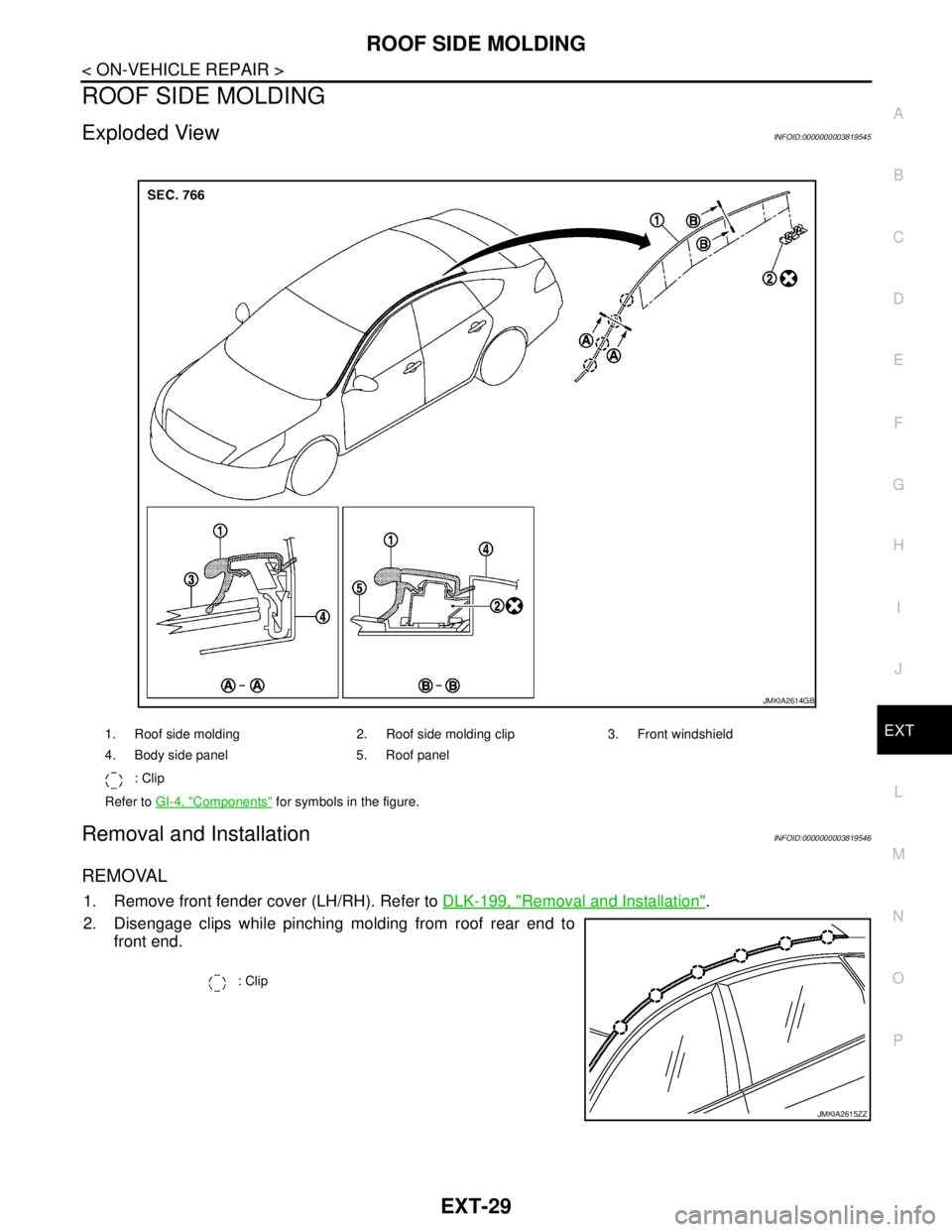
Exploded ViewINFOID:0000000003819545
Removal and InstallationINFOID:0000000003819546
REMOVAL
1. Remove front fender cover (LH/RH). Refer to DLK-199, "Removal and Installation".
2. Disengage clips while pinching molding from roof rear end to
front end.
1. Roof side molding 2. Roof side molding clip 3. Front windshield
4. Body side panel 5. Roof panel
: Clip
Refer to GI-4, "
Components" for symbols in the figure.
JMKIA2614GB
: Clip
JMKIA2615ZZ
Page 2419 of 5121
EXT-30
< ON-VEHICLE REPAIR >
ROOF SIDE MOLDING
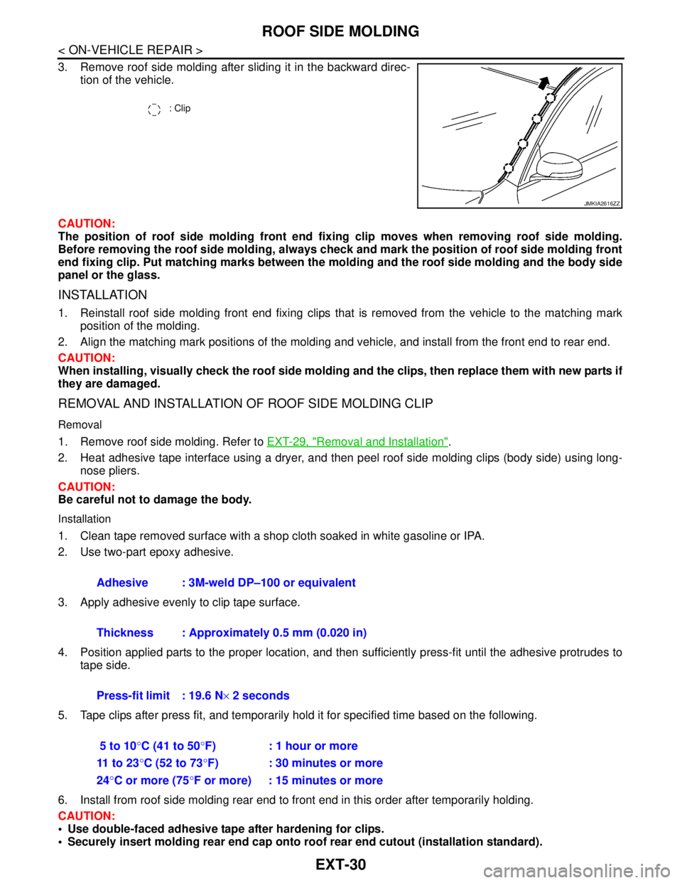
3. Remove roof side molding after sliding it in the backward direc-
tion of the vehicle.
CAUTION:
The position of roof side molding front end fixing clip moves when removing roof side molding.
Before removing the roof side molding, always check and mark the position of roof side molding front
end fixing clip. Put matching marks between the molding and the roof side molding and the body side
panel or the glass.
INSTALLATION
1. Reinstall roof side molding front end fixing clips that is removed from the vehicle to the matching mark
position of the molding.
2. Align the matching mark positions of the molding and vehicle, and install from the front end to rear end.
CAUTION:
When installing, visually check the roof side molding and the clips, then replace them with new parts if
they are damaged.
REMOVAL AND INSTALLATION OF ROOF SIDE MOLDING CLIP
Removal
1. Remove roof side molding. Refer to EXT-29, "Removal and Installation".
2. Heat adhesive tape interface using a dryer, and then peel roof side molding clips (body side) using long-
nose pliers.
CAUTION:
Be careful not to damage the body.
Installation
1. Clean tape removed surface with a shop cloth soaked in white gasoline or IPA.
2. Use two-part epoxy adhesive.
3. Apply adhesive evenly to clip tape surface.
4. Position applied parts to the proper location, and then sufficiently press-fit until the adhesive protrudes to
tape side.
5. Tape clips after press fit, and temporarily hold it for specified time based on the following.
6. Install from roof side molding rear end to front end in this order after temporarily holding.
CAUTION:
Use double-faced adhesive tape after hardening for clips.
Securely insert molding rear end cap onto roof rear end cutout (installation standard).
: Clip
JMKIA2616ZZ
Adhesive : 3M-weld DP–100 or equivalent
Thickness : Approximately 0.5 mm (0.020 in)
Press-fit limit : 19.6 N× 2 seconds
5 to 10°C (41 to 50°F) : 1 hour or more
11 t o 2 3°C (52 to 73°F) : 30 minutes or more
24°C or more (75°F or more) : 15 minutes or more
Page 2420 of 5121
ROOF SIDE MOLDING
EXT-31
< ON-VEHICLE REPAIR >
C
D
E
F
G
H
I
J
L
MA
B
EXT
N
O
P
When installing roof side molding of windshield portion, check that molding fastener is securely
inserted and then press in.
Never wash the vehicle with in 24 hours so as to keep adhesive.