2008 NISSAN TEANA check oil
[x] Cancel search: check oilPage 3808 of 5121
PRECAUTIONS
RF-77
< PRECAUTION >
C
D
E
F
G
H
I
J
L
MA
B
RF
N
O
P
PRECAUTION
PRECAUTIONS
Precaution for Supplemental Restraint System (SRS) "AIR BAG" and "SEAT BELT
PRE-TENSIONER"
INFOID:0000000003940151
The Supplemental Restraint System such as “AIR BAG” and “SEAT BELT PRE-TENSIONER”, used along
with a front seat belt, helps to reduce the risk or severity of injury to the driver and front passenger for certain
types of collision. Information necessary to service the system safely is included in the “SRS AIRBAG” and
“SEAT BELT” of this Service Manual.
WARNING:
To avoid rendering the SRS inoperative, which could increase the risk of personal injury or death in
the event of a collision which would result in air bag inflation, all maintenance must be performed by
an authorized NISSAN/INFINITI dealer.
Improper maintenance, including incorrect removal and installation of the SRS, can lead to personal
injury caused by unintentional activation of the system. For removal of Spiral Cable and Air Bag
Module, see the “SRS AIRBAG”.
Never use electrical test equipment on any circuit related to the SRS unless instructed to in this Ser-
vice Manual. SRS wiring harnesses can be identified by yellow and/or orange harnesses or harness
connectors.
Service NoticeINFOID:0000000003812880
When removing or installing various parts, place a cloth or padding onto the vehicle body to prevent
scratches.
Handle trim, molding, instruments, grille, etc. carefully during removing or installing. Be careful not to oil or
damage them.
Apply sealing compound where necessary when installing parts.
When applying sealing compound, be careful that the sealing compound does not protrude from parts.
When replacing any metal parts (for example body outer panel, members, etc.), be sure to take rust preven-
tion measures.
Precaution for WorkINFOID:0000000003812881
When removing or disassembling each component, be careful not to damage or deform it. If a component
may be subject to interference, be sure to protect it with a shop cloth.
When removing (disengaging) components with a screwdriver or similar tool, be sure to wrap the component
with a shop cloth or vinyl tape to protect it.
Protect the removed parts with a shop cloth and keep them.
Replace a deformed or damaged clip.
If a part is specified as a non-reusable part, always replace it with new one.
Be sure to tighten bolts and nuts securely to the specified torque.
After re-installation is completed, be sure to check that each part works normally.
Follow the steps below to clean components.
- Water soluble foul: Dip a soft cloth into lukewarm water, and wring the water out of the cloth to wipe the
fouled area.
Then rub with a soft and dry cloth.
- Oily foul: Dip a soft cloth into lukewarm water with mild detergent (concentration: within 2 to 3%), and wipe
the fouled area.
Then dip a cloth into fresh water, and wring the water out of the cloth to wipe the detergent off. Then rub with
a soft and dry cloth.
Do not use organic solvent such as thinner, benzene, alcohol, and gasoline.
For genuine leather seats, use a genuine leather seat cleaner.
Page 3835 of 5121
PRECAUTIONS
RSU-3
< PRECAUTION >
C
D
F
G
H
I
J
K
L
MA
B
RSU
N
O
P
PRECAUTION
PRECAUTIONS
Precautions for SuspensionINFOID:0000000003811137
CAUTION:
• When installing rubber bushings, the final tightening must be carried out under unladen conditions
with tires on ground. Oil might shorten the life of rubber bushings. Be sure to wipe off any spilled oil.
- Unladen conditions mean that fuel, engine coolant and lubricant are full. Spare tire, jack, hand tools
and mats are in designated positions.
After servicing suspension parts, be sure to check wheel alignment.
Self-lock nuts are not reusable. Always use new ones when installing. Since new self-lock nuts are
pre-oiled, tighten as they are.
Page 3837 of 5121
REAR SUSPENSION ASSEMBLY
RSU-5
< ON-VEHICLE MAINTENANCE >
C
D
F
G
H
I
J
K
L
MA
B
RSU
N
O
P
ON-VEHICLE MAINTENANCE
REAR SUSPENSION ASSEMBLY
InspectionINFOID:0000000003811139
MOUNTING INSPECTION
Make sure the mounting conditions (looseness, backlash) of each component and component conditions
(wear, damage) are normal.
SHOCK ABSORBER
Check for oil leakage and damage. Replace if necessary.
Page 3841 of 5121

REAR LOWER LINK & COIL SPRING
RSU-9
< ON-VEHICLE REPAIR >
C
D
F
G
H
I
J
K
L
MA
B
RSU
N
O
P
Install coil spring by aligning lower end of the coil spring to step (A)
between rubber seat (1) and rear lower link (2).
CAUTION:
Set coil spring so that its paint marks are aligned with the
positions of 3.0 turns (2 places) and 4.0 turns (1 place) or 4.0
turns (2 places) and 5.0 turns (1 place) from the bottom end of
the coil spring.
Perform the final tightening of rear suspension member and axle
installation position (rubber bushing) under unladen condition with
tires on level ground.
InspectionINFOID:0000000003811144
INSPECTION AFTER REMOVAL
Check lower link, bushing and coil spring for deformation, crack, and damage. Replace if necessary.
INSPECTION AFTER INSTALLATION
1. Check wheel alignment. Refer to RSU-6, "Inspection".
2. Adjust neutral position of steering angle sensor (with VDC). Refer to BRC-66, "
ADJUSTMENT OF
STEERING ANGLE SENSOR NEUTRAL POSITION : Special Repair Requirement".
JPEIB0122ZZ
Page 3843 of 5121
REAR SHOCK ABSORBER
RSU-11
< ON-VEHICLE REPAIR >
C
D
F
G
H
I
J
K
L
MA
B
RSU
N
O
P
Check the following items, and replace the if necessary.
Shock absorber for deformation, cracks, damage.
Welded and sealed areas for oil leakage.
Piston rod for damage, uneven wear or distortion.
Seal of shock absorber mounting bracket for cracks, damage and come off.
INSPECTION AFTER INSTALLATION
Check wheel sensor harness for proper connection. Refer to BRC-58, "REAR WHEEL SENSOR : Exploded
View" (without VDC), BRC-152, "REAR WHEEL SENSOR : Exploded View" (with VDC).
Page 3844 of 5121
RSU-12
< ON-VEHICLE REPAIR >
RADIUS ROD
RADIUS ROD
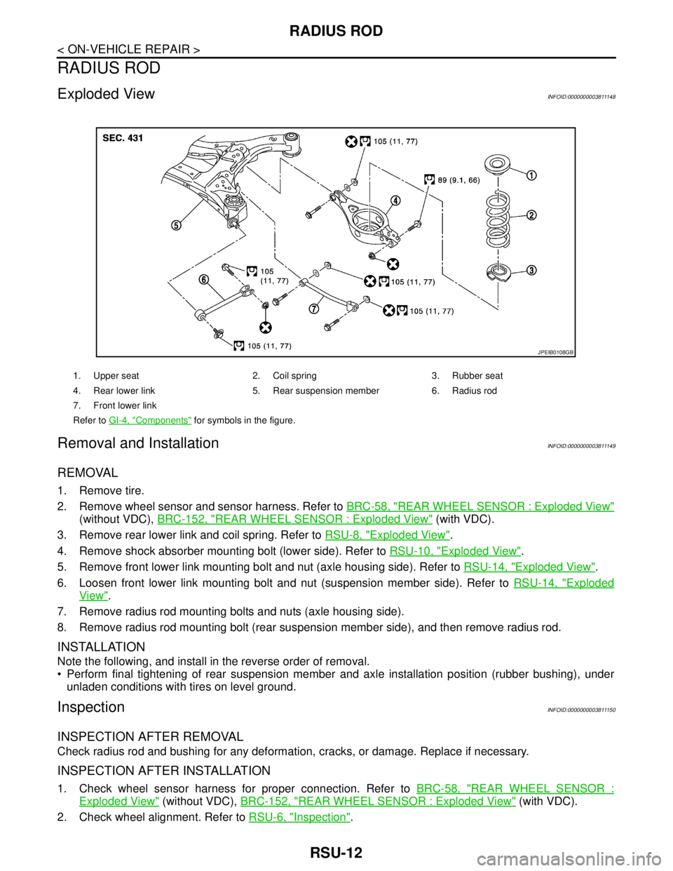
Exploded ViewINFOID:0000000003811148
Removal and InstallationINFOID:0000000003811149
REMOVAL
1. Remove tire.
2. Remove wheel sensor and sensor harness. Refer to BRC-58, "
REAR WHEEL SENSOR : Exploded View"
(without VDC), BRC-152, "REAR WHEEL SENSOR : Exploded View" (with VDC).
3. Remove rear lower link and coil spring. Refer to RSU-8, "
Exploded View".
4. Remove shock absorber mounting bolt (lower side). Refer to RSU-10, "
Exploded View".
5. Remove front lower link mounting bolt and nut (axle housing side). Refer to RSU-14, "
Exploded View".
6. Loosen front lower link mounting bolt and nut (suspension member side). Refer to RSU-14, "
Exploded
View".
7. Remove radius rod mounting bolts and nuts (axle housing side).
8. Remove radius rod mounting bolt (rear suspension member side), and then remove radius rod.
INSTALLATION
Note the following, and install in the reverse order of removal.
Perform final tightening of rear suspension member and axle installation position (rubber bushing), under
unladen conditions with tires on level ground.
InspectionINFOID:0000000003811150
INSPECTION AFTER REMOVAL
Check radius rod and bushing for any deformation, cracks, or damage. Replace if necessary.
INSPECTION AFTER INSTALLATION
1. Check wheel sensor harness for proper connection. Refer to BRC-58, "REAR WHEEL SENSOR :
Exploded View" (without VDC), BRC-152, "REAR WHEEL SENSOR : Exploded View" (with VDC).
2. Check wheel alignment. Refer to RSU-6, "
Inspection".
1. Upper seat 2. Coil spring 3. Rubber seat
4. Rear lower link 5. Rear suspension member 6. Radius rod
7. Front lower link
Refer to GI-4, "
Components" for symbols in the figure.
JPEIB0108GB
Page 3846 of 5121
RSU-14
< ON-VEHICLE REPAIR >
FRONT LOWER LINK
FRONT LOWER LINK
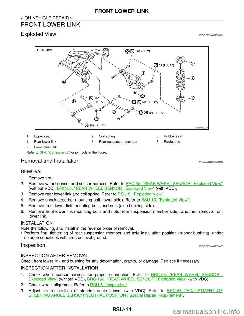
Exploded ViewINFOID:0000000003811151
Removal and InstallationINFOID:0000000003811152
REMOVAL
1. Remove tire.
2. Remove wheel sensor and sensor harness. Refer to BRC-58, "
REAR WHEEL SENSOR : Exploded View"
(without VDC), BRC-58, "REAR WHEEL SENSOR : Exploded View" (with VDC).
3. Remove rear lower link and coil spring. Refer to RSU-8, "
Exploded View".
4. Remove shock absorber mounting bolt (lower side). Refer to RSU-10, "
Exploded View".
5. Remove front lower link mounting bolts and nuts (axle housing side).
6. Remove front lower link mounting bolts and nuts (rear suspension member side), and then remove front
lower link.
INSTALLATION
Note the following, and install in the reverse order of removal.
Perform final tightening of rear suspension member and axle installation position (rubber bushing), under
unladen conditions with tires on level ground.
InspectionINFOID:0000000003811153
INSPECTION AFTER REMOVAL
Check front lower link and bushing for any deformation, cracks, or damage. Replace if necessary.
INSPECTION AFTER INSTALLATION
1. Check wheel sensor harness for proper connection. Refer to BRC-58, "REAR WHEEL SENSOR :
Exploded View" (without VDC), BRC-152, "REAR WHEEL SENSOR : Exploded View" (with VDC).
2. Check wheel alignment. Refer to RSU-6, "
Inspection".
3. Adjust neutral position of steering angle sensor (with VDC). Refer to BRC-66, "
ADJUSTMENT OF
STEERING ANGLE SENSOR NEUTRAL POSITION : Special Repair Requirement".
1. Upper seat 2. Coil spring 3. Rubber seat
4. Rear lower link 5. Rear suspension member 6. Radius rod
7. Front lower link
Refer to GI-4, "
Components" for symbols in the figure.
JPEIB0108GB
Page 3854 of 5121
SB-2
< PRECAUTION >
PRECAUTIONS
PRECAUTION
PRECAUTIONS
Precaution for Supplemental Restraint System (SRS) "AIR BAG" and "SEAT BELT
PRE-TENSIONER"
INFOID:0000000003949049
The Supplemental Restraint System such as “AIR BAG” and “SEAT BELT PRE-TENSIONER”, used along
with a front seat belt, helps to reduce the risk or severity of injury to the driver and front passenger for certain
types of collision. Information necessary to service the system safely is included in the “SRS AIRBAG” and
“SEAT BELT” of this Service Manual.
WARNING:
• To avoid rendering the SRS inoperative, which could increase the risk of personal injury or death in
the event of a collision which would result in air bag inflation, all maintenance must be performed by
an authorized NISSAN/INFINITI dealer.
Improper maintenance, including incorrect removal and installation of the SRS, can lead to personal
injury caused by unintentional activation of the system. For removal of Spiral Cable and Air Bag
Module, see the “SRS AIRBAG”.
Never use electrical test equipment on any circuit related to the SRS unless instructed to in this Ser-
vice Manual. SRS wiring harnesses can be identified by yellow and/or orange harnesses or harness
connectors.
Precaution for Seat Belt ServiceINFOID:0000000003848851
CAUTION:
Before removing the front seat belt pre-tensioner assembly, turn the ignition switch OFF, disconnect
both battery cables and wait at least 3 minutes.
Never use electrical test equipment for front seat belt pre-tensioner connector.
After replacing or reinstalling front seat belt pre-tensioner assembly, or reconnecting front seat belt
pre-tensioner connector, check the system function. Refer to SRC-10, "
Diagnosis Description".
Deploy front seat belt pre-tensioner assembly before disposing. Refer to SR-25, "
Caution for Air Bag
Module and Seat Belt Pre-tensioner"
Never use disassembled buckle or seat belt assembly.
Replace anchor bolts if they are deformed or worn out.
Never oil tongue and buckle.
If any component of seat belt assembly is questionable, never repair. Replace the entire seat belt
assembly.
If webbing is cut, frayed or damaged, replace seat belt assembly.
When replacing seat belt assembly, use a Genuine NISSAN seat belt assembly.
AFTER A COLLISION
WARNING:
Inspect all seat belt assemblies including retractors and attached hardware after any collision.
NISSAN recommends that all seat belt assemblies in use during a collision be replaced unless the col-
lision was minor and the belts show no damage and continue to operate properly. Not doing so could
result in serious personal injury in an accident. Seat belt assemblies not in use during a collision
should also be replaced if either damage or improper operation is noted. Seat belt pre-tensioners
should be replaced even if the seat belts are not in use during a frontal collision in which the air bags
are deployed.
Replace any seat belt assembly (including anchor bolts) if:
The seat belt is in use at the time of a collision (except for minor collisions and the belts, retractors and buck-
les show no damage and continue to operate properly).
The seat belt is damaged in an accident (i.e. torn webbing, bent retractor or guide).
The seat belt attaching point is damaged in an accident. Inspect the seat belt attaching area for damage or
distortion and repair as necessary before installing a new seat belt assembly.
Anchor bolts are deformed or worn out.
The front seat belt pre-tensioner must be replaced even if the seat belts are not in use during the collision in
which the air bags are deployed.