2008 NISSAN TEANA check oil
[x] Cancel search: check oilPage 3289 of 5121

MWI
DIAGNOSIS SYSTEM (METER)
MWI-35
< FUNCTION DIAGNOSIS >
C
D
E
F
G
H
I
J
K
L
MB A
O
P
NOTE:
Some items are not available according to vehicle specification.
SPECIAL FUNCTION
Special menu
W/L ON HISTORY
Stores histories when warning/indicator lamp is turned on.
“W/L ON HISTORY” indicates the “TIME” when the warning/ indicator lamp is turned on.
The “TIME” above is :
SHIFT IND
[P, R, N, D, L]Status of shift position indicator detected from shift position signal and manual
mode indicator signal is received from TCM via CAN communication.
O/D OFF SW
[On/Off] Status of sport mode switch.
M RANGE SW
[On/Off]This item is displayed, but cannot be monitored.
NM RANGE SW
[On/Off]This item is displayed, but cannot be monitored.
AT SFT UP SW
[On/Off]This item is displayed, but cannot be monitored.
AT SFT DWN SW
[On/Off]This item is displayed, but cannot be monitored.
ST SFT UP SW
[On/Off]This item is displayed, but cannot be monitored.
ST SFT DWN SW
[On/Off]This item is displayed, but cannot be monitored.
PKB SW
[On/Off]Status of parking brake switch.
BUCKLE SW
[On/Off]Status of seat belt buckle switch.
BRAKE OIL SW
[On/Off]Status of brake fluid level switch.
DISTANCE
[km]Value of possible driving distance calculated by combination meter.
A/C AMP CONN
[On/Off]Input status of A/C auto amp. connection recognition signal.
ENTER SW
[On/Off]Status of (ENTER) switch.
SELECT SW
[On/Off]Status of (SELECT) switch.
OUTSIDE TEMP
[°C or °F]Ambient air temperature value converted from ambient sensor signal received
from ambient sensor.
NOTE:
This may not match with the temperature value indicated on the information dis-
play. (Because the information display value is a corrected value from the ambient
sensor input value.)
FUEL LOW SIG
[On/Off]Status of fuel level low warning signal to output to AV control unit via CAN com-
munication.
BUZZER
[On/Off]XBuzzer status (in the combination meter) is detected from the buzzer output signal
received from each unit via CAN communication and the warning output condition
of the combination meter. Display item [Unit]MAIN
SIGNALSDescription
Display item Description
W/L ON HISTORY Lighting history of warning lamp and indicator lamp can be checked.
Page 3304 of 5121

MWI-50
< COMPONENT DIAGNOSIS >
OIL PRESSURE SWITCH SIGNAL CIRCUIT
OIL PRESSURE SWITCH SIGNAL CIRCUIT
DescriptionINFOID:0000000003792577
Detects the engine oil pressure and transmits the oil pressure switch signal to IPDM E/R.
Component Function CheckINFOID:0000000003792578
1.CHECK COMBINATION METER INPUT SIGNAL
Select the “Data Monitor” for the “METER/M&A” and check the “OIL W/L” monitor value.
>> INSPECTION END
Diagnosis ProcedureINFOID:0000000003792579
1.CHECK OIL PRESSURE SWITCH CIRCUIT
1. Turn ignition switch OFF.
2. Disconnect IPDM E/R connector and oil pressure switch connector.
3. Check continuity between IPDM E/R harness connector terminal and oil pressure switch harness connec-
tor terminal.
4. Check continuity between IPDM E/R harness connector terminal and ground.
Is the inspection result normal?
YES >> INSPECTION END
NO >> Repair harness or connector.
Component InspectionINFOID:0000000003792580
1.CHECK OIL PRESSURE SWITCH UNIT
“OIL W/L”
Ignition switch ON : On
Engine running : Off
Te r m i n a l s
Continuity (+) (-)
IPDM E/R Oil pressure switch
Connector Terminal Connector Terminal
F12 75 F63 1 Existed
Te r m i n a l s
Continuity (+) (-)
IPDM E/R
Ground Connector Terminal
F12 75 Not existed
Page 3305 of 5121

MWI
OIL PRESSURE SWITCH SIGNAL CIRCUIT
MWI-51
< COMPONENT DIAGNOSIS >
C
D
E
F
G
H
I
J
K
L
MB A
O
P
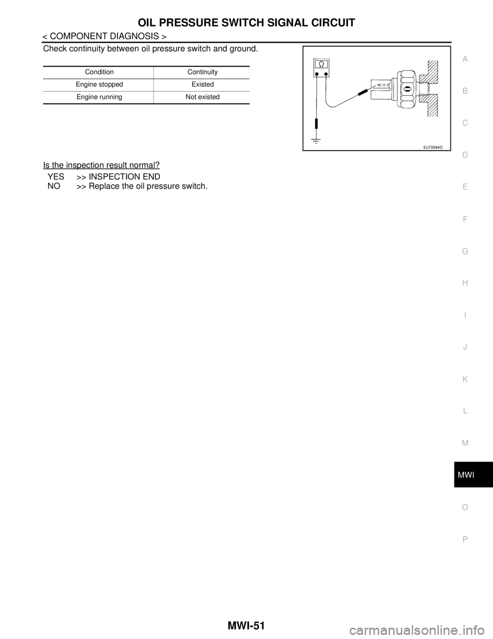
Check continuity between oil pressure switch and ground.
Is the inspection result normal?
YES >> INSPECTION END
NO >> Replace the oil pressure switch.
Condition Continuity
Engine stopped Existed
Engine running Not existed
ELF0044D
Page 3372 of 5121

MWI-118
< SYMPTOM DIAGNOSIS >
THE OIL PRESSURE WARNING LAMP DOES NOT TURN ON
THE OIL PRESSURE WARNING LAMP DOES NOT TURN ON
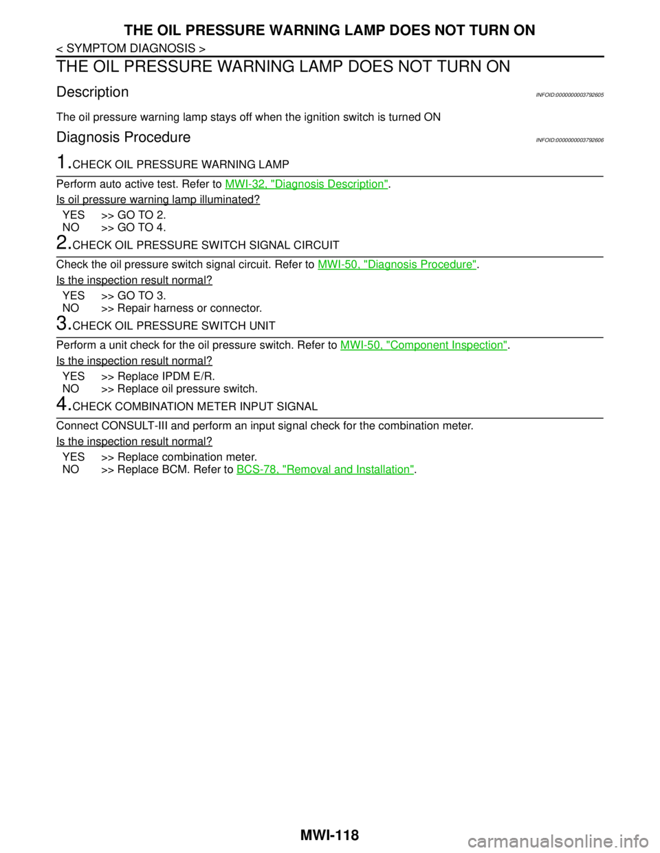
DescriptionINFOID:0000000003792605
The oil pressure warning lamp stays off when the ignition switch is turned ON
Diagnosis ProcedureINFOID:0000000003792606
1.CHECK OIL PRESSURE WARNING LAMP
Perform auto active test. Refer to MWI-32, "
Diagnosis Description".
Is oil pressure warning lamp illuminated?
YES >> GO TO 2.
NO >> GO TO 4.
2.CHECK OIL PRESSURE SWITCH SIGNAL CIRCUIT
Check the oil pressure switch signal circuit. Refer to MWI-50, "
Diagnosis Procedure".
Is the inspection result normal?
YES >> GO TO 3.
NO >> Repair harness or connector.
3.CHECK OIL PRESSURE SWITCH UNIT
Perform a unit check for the oil pressure switch. Refer to MWI-50, "
Component Inspection".
Is the inspection result normal?
YES >> Replace IPDM E/R.
NO >> Replace oil pressure switch.
4.CHECK COMBINATION METER INPUT SIGNAL
Connect CONSULT-III and perform an input signal check for the combination meter.
Is the inspection result normal?
YES >> Replace combination meter.
NO >> Replace BCM. Refer to BCS-78, "
Removal and Installation".
Page 3373 of 5121

MWI
THE OIL PRESSURE WARNING LAMP DOES NOT TURN OFF
MWI-119
< SYMPTOM DIAGNOSIS >
C
D
E
F
G
H
I
J
K
L
MB A
O
P
THE OIL PRESSURE WARNING LAMP DOES NOT TURN OFF
DescriptionINFOID:0000000003792607
The oil pressure warning lamp remains illuminated while the engine is running (normal oil pressure)
Diagnosis ProcedureINFOID:0000000003792608
1.CHECK OIL PRESSURE WARNING LAMP
Perform auto active test. Refer to MWI-32, "
Diagnosis Description".
Is oil pressure warning lamp illuminated?
YES >> GO TO 2.
NO >> GO TO 5.
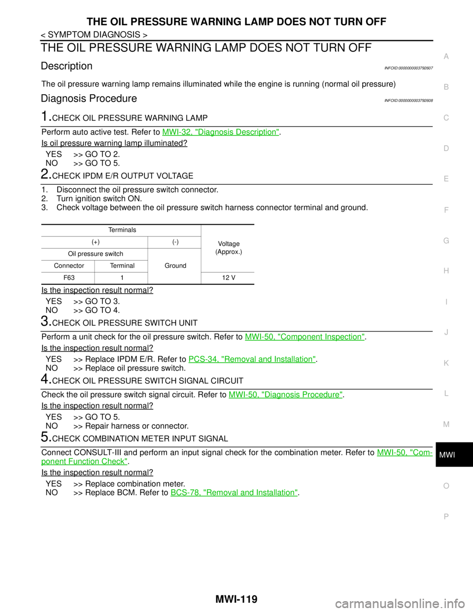
2.CHECK IPDM E/R OUTPUT VOLTAGE
1. Disconnect the oil pressure switch connector.
2. Turn ignition switch ON.
3. Check voltage between the oil pressure switch harness connector terminal and ground.
Is the inspection result normal?
YES >> GO TO 3.
NO >> GO TO 4.
3.CHECK OIL PRESSURE SWITCH UNIT
Perform a unit check for the oil pressure switch. Refer to MWI-50, "
Component Inspection".
Is the inspection result normal?
YES >> Replace IPDM E/R. Refer to PCS-34, "Removal and Installation".
NO >> Replace oil pressure switch.
4.CHECK OIL PRESSURE SWITCH SIGNAL CIRCUIT
Check the oil pressure switch signal circuit. Refer to MWI-50, "
Diagnosis Procedure".
Is the inspection result normal?
YES >> GO TO 5.
NO >> Repair harness or connector.
5.CHECK COMBINATION METER INPUT SIGNAL
Connect CONSULT-III and perform an input signal check for the combination meter. Refer to MWI-50, "
Com-
ponent Function Check".
Is the inspection result normal?
YES >> Replace combination meter.
NO >> Replace BCM. Refer to BCS-78, "
Removal and Installation".
Te r m i n a l s
Voltag e
(Approx.) (+) (-)
Oil pressure switch
Ground Connector Terminal
F63 1 12 V
Page 3402 of 5121
![NISSAN TEANA 2008 Service Manual PCS
DIAGNOSIS SYSTEM (IPDM E/R)
PCS-11
< FUNCTION DIAGNOSIS >[IPDM E/R]
C
D
E
F
G
H
I
J
K
L B A
O
P N
DIAGNOSIS SYSTEM (IPDM E/R)
Diagnosis DescriptionINFOID:0000000003773267
AUTO ACTIVE TEST
Descript NISSAN TEANA 2008 Service Manual PCS
DIAGNOSIS SYSTEM (IPDM E/R)
PCS-11
< FUNCTION DIAGNOSIS >[IPDM E/R]
C
D
E
F
G
H
I
J
K
L B A
O
P N
DIAGNOSIS SYSTEM (IPDM E/R)
Diagnosis DescriptionINFOID:0000000003773267
AUTO ACTIVE TEST
Descript](/manual-img/5/57391/w960_57391-3401.png)
PCS
DIAGNOSIS SYSTEM (IPDM E/R)
PCS-11
< FUNCTION DIAGNOSIS >[IPDM E/R]
C
D
E
F
G
H
I
J
K
L B A
O
P N
DIAGNOSIS SYSTEM (IPDM E/R)
Diagnosis DescriptionINFOID:0000000003773267
AUTO ACTIVE TEST
Description
In auto active test mode, the IPDM E/R sends a drive signal to the following systems to check their operation.
Oil pressure warning lamp
Front wiper (LO, HI)
Parking lamps
License plate lamps
Tail lamps
Front fog lamps
Headlamps (LO, HI)
A/C compressor (magnet clutch)
Cooling fan
Operation Procedure
1. Close the hood and lift the wiper arms from the windshield. (Prevent windshield damage due to wiper
operation)
NOTE:
When auto active test is performed with hood opened, sprinkle water on windshield beforehand.
2. Turn ignition switch OFF.
3. Turn the ignition switch ON, and within 20 seconds, press the driver door switch 10 times. Then turn the
ignition switch OFF.
CAUTION:
Close passenger door.
4. Turn the ignition switch ON within 10 seconds. After that the horn sounds once and the auto active test
starts.
5. The oil pressure warning lamp starts blinking when the auto active test starts.
6. After a series of the following operations is repeated 3 times, auto active test is completed.
NOTE:
When auto active test mode has to be cancelled halfway through test, turn ignition switch OFF.
CAUTION:
• If auto active test mode cannot be actuated, check door switch system. Refer to DLK-57,
"ComponentFunctionCheck".
Do not start the engine.
Inspection in Auto Active Test Mode
When auto active test mode is actuated, the following 5 steps are repeated 3 times.
Operation
sequenceInspection location Operation
A Oil pressure warning lamp Blinks continuously during operation of auto active test
1 Front wiper LO for 5 seconds → HI for 5 seconds
2Parking lamps
License plate lamps
Tail lamps
Front fog lamps10 seconds
3 Headlamps LO ⇔ HI 5 times
4 A/C compressor (magnet clutch) ON ⇔ OFF 5 times
5 Cooling fan LO for 5 seconds → MID for 3 seconds → HI for 2 seconds
Page 3408 of 5121
![NISSAN TEANA 2008 Service Manual PCS
B2098 IGNITION RELAY ON STUCK
PCS-17
< COMPONENT DIAGNOSIS >[IPDM E/R]
C
D
E
F
G
H
I
J
K
L B A
O
P N
B2098 IGNITION RELAY ON STUCK
DescriptionINFOID:0000000003773272
IPDM E/R operates the igniti NISSAN TEANA 2008 Service Manual PCS
B2098 IGNITION RELAY ON STUCK
PCS-17
< COMPONENT DIAGNOSIS >[IPDM E/R]
C
D
E
F
G
H
I
J
K
L B A
O
P N
B2098 IGNITION RELAY ON STUCK
DescriptionINFOID:0000000003773272
IPDM E/R operates the igniti](/manual-img/5/57391/w960_57391-3407.png)
PCS
B2098 IGNITION RELAY ON STUCK
PCS-17
< COMPONENT DIAGNOSIS >[IPDM E/R]
C
D
E
F
G
H
I
J
K
L B A
O
P N
B2098 IGNITION RELAY ON STUCK
DescriptionINFOID:0000000003773272
IPDM E/R operates the ignition relay when it receives an ignition switch ON signal from BCM via CAN com-
munication.
Turn the ignition relay OFF by pressing the push-button ignition switch once when the vehicle speed is 4 km/
h (2.5 MPH) or less.
Turn the ignition relay OFF with the following operation when the vehicle speed is more than 4 km/h (2.5
MPH) or when an abnormal condition occurs in CAN communication from the combination meter (Emer-
gency OFF)
- Press and hold the push-button ignition switch for 2 seconds or more.
- Press the push-button ignition switch 3 times within 1.5 seconds.
NOTE:
The ignition relay does not turn ON for 3 seconds after emergency OFF even if the push-button ignition switch
is pressed.
DTC LogicINFOID:0000000003773273
DTC DETECTION LOGIC
Diagnosis ProcedureINFOID:0000000003773274
1.PERFORM SELF DIAGNOSIS
1. Turn ignition switch ON.
2. Erase “Self Diagnostic Result” of IPDM E/R.
3. Turn ignition switch OFF, and wait for 1 second or more.
4. Turn ignition switch ON. Check “Self Diagnostic Result” again.
Is
“IGN RELAY ON” displayed?
YES >> Replace IPDM E/R.
NO >> Refer to GI-35, "
Intermittent Incident".
DTCCONSULT-III dis-
play descriptionDTC Detection Condition Possible causes
B2098 IGN RELAY ONThe ignition relay ON is detected for 1 second at ignition switch OFF
(CPU monitors the status at the contact and excitation coil circuits of
the ignition relay inside it)Ignition relay malfunction
Page 3409 of 5121
![NISSAN TEANA 2008 Service Manual PCS-18
< COMPONENT DIAGNOSIS >[IPDM E/R]
B2099 IGNITION RELAY OFF STUCK
B2099 IGNITION RELAY OFF STUCK
DescriptionINFOID:0000000003773275
IPDM E/R operates the ignition relay when it receives an ign NISSAN TEANA 2008 Service Manual PCS-18
< COMPONENT DIAGNOSIS >[IPDM E/R]
B2099 IGNITION RELAY OFF STUCK
B2099 IGNITION RELAY OFF STUCK
DescriptionINFOID:0000000003773275
IPDM E/R operates the ignition relay when it receives an ign](/manual-img/5/57391/w960_57391-3408.png)
PCS-18
< COMPONENT DIAGNOSIS >[IPDM E/R]
B2099 IGNITION RELAY OFF STUCK
B2099 IGNITION RELAY OFF STUCK
DescriptionINFOID:0000000003773275
IPDM E/R operates the ignition relay when it receives an ignition switch ON signal from BCM via CAN com-
munication.
Turn the ignition relay OFF by pressing the push-button ignition switch once when the vehicle speed is 4 km/
h (2.5 MPH) or less.
Turn the ignition relay OFF with the following operation when the vehicle speed is more than 4 km/h (2.5
MPH) or when an abnormal condition occurs in CAN communication from the combination meter (Emer-
gency OFF)
- Press and hold the push-button ignition switch for 2 seconds or more.
- Press the push-button ignition switch 3 times within 1.5 seconds.
NOTE:
The ignition relay does not turn ON for 3 seconds after emergency OFF even if the push-button ignition switch
is pressed.
DTC LogicINFOID:0000000003773276
DTC DETECTION LOGIC
NOTE:
When IPDM E/R power supply voltage is low (Approx. 7 - 8 V for about 1 second), the “DTC: B2099” may be detected.
Diagnosis ProcedureINFOID:0000000003773277
1.PERFORM SELF DIAGNOSIS
1. Turn ignition switch ON.
2. Erase “Self Diagnostic Result”.
3. Turn ignition switch OFF.
4. Turn ignition switch ON. Check “Self Diagnostic Result” again.
Is
“IGN RELAY OFF” displayed?
YES >> Replace IPDM E/R.
NO >> Refer to GI-35, "
Intermittent Incident".
DTCCONSULT-III dis-
play descriptionDTC Detection Condition Possible causes
B2099 IGN RELAY OFFThe ignition relay OFF is detected for 1 second at ignition switch ON
(CPU monitors the status at the contact and excitation coil circuits of
the ignition relay inside it)Ignition relay malfunction