2008 INFINITI FX35 power supply
[x] Cancel search: power supplyPage 2894 of 3924
GI-32
< SERVICE INFORMATION >
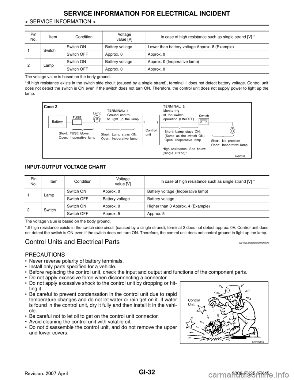
SERVICE INFORMATION FOR ELECTRICAL INCIDENT
The voltage value is based on the body ground.
*:If high resistance exists in the switch side circuit (caused by a single strand), terminal 1 does not detect battery voltage. Control unit
does not detect the switch is ON even if the switch does not turn ON. Therefore, the control unit does not supply power to ligh t up the
lamp.
INPUT-OUTPUT VOLTAGE CHART
The voltage value is based on the body ground.
*:If high resistance exists in the switch side circuit (caused by a single strand), terminal 2 does not detect approx. 0V. Cont rol unit does
not detect the switch is ON even if the switch does not turn ON. Therefore, the control unit does not control ground to light u p the lamp.
Control Units and Electrical PartsINFOID:0000000001325673
PRECAUTIONS
Never reverse polarity of battery terminals.
Install only parts specified for a vehicle.
Before replacing the control unit, check the input and output and functions of the component parts.
Do not apply excessive force when disconnecting a connector.
Do not apply excessive shock to the control unit by dropping or hit- ting it.
Be careful to prevent condensation in the control unit due to rapid temperature changes and do not let water or rain get on it. If water
is found in the control unit, dry it fully and then install it in the vehi-
cle.
Be careful not to let oil to get on the control unit connector.
Avoid cleaning the control unit with volatile oil.
Do not disassemble the control unit, and do not remove the upper and lower covers.
Pin
No. Item Condition
Vo l ta g e
value [V] In case of high resistance such as single strand [V] *
1Switch Switch ON Battery voltage Lower than battery voltage Approx. 8 (Example)
Switch OFF Approx. 0 Approx. 0
2Lamp Switch ON Battery voltage App
rox. 0 (Inoperative lamp)
Switch OFF Approx. 0 Approx. 0
MGI035A
Pin
No. Item Condition
Vo l ta g e
value [V] In case of high resistance such as single strand [V] *
1Lamp Switch ON Approx. 0 Battery voltage (Inoperative lamp)
Switch OFF Battery voltage Battery voltage
2Switch Switch ON Approx. 0 Higher than 0 Approx. 4 (Example)
Switch OFF Approx. 5 Approx. 5
SAIA0255E
3AA93ABC3ACD3AC03ACA3AC03AC63AC53A913A773A893A873A873A8E3A773A983AC73AC93AC03AC3
3A893A873A873A8F3A773A9D3AAF3A8A3A8C3A863A9D3AAF3A8B3A8C
Page 2897 of 3924
CONSULT-III/GST CHECKING SYSTEMGI-35
< SERVICE INFORMATION >
C
DE
F
G H
I
J
K L
M B
GI
N
O P
CONSULT-III/GST Data Link Connector (DLC) CircuitINFOID:0000000001572195
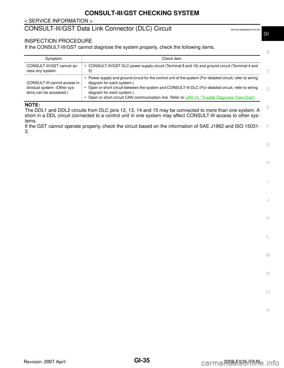
INSPECTION PROCEDURE
If the CONSULT-III/GST cannot diagnose the system properly, check the following items.
NOTE:
The DDL1 and DDL2 circuits from DLC pins 12, 13, 14 and 15 may be connected to more than one system. A
short in a DDL circuit connected to a control unit in one system may affect CONSULT-III access to other sys-
tems.
If the GST cannot operate properly, check the circuit based on the information of SAE J1962 and ISO 15031-
3.
Symptom Check item
CONSULT-III/GST cannot ac-
cess any system. CONSULT-III/GST DLC power supply circuit (Terminal 8 and 16) and ground circuit (Terminal 4 and
5)
CONSULT-III cannot access in-
dividual system. (Other sys-
tems can be accessed.) Power supply and ground circuit for the control unit of the system (For detailed circuit, refer to wiring
diagram for each system.)
Open or short circuit between the system and CONSULT-III DLC (For detailed circuit, refer to wiring
diagram for each system.)
Open or short circuit CAN communication line. Refer to LAN-14, "
Trouble Diagnosis Flow Chart".
3AA93ABC3ACD3AC03ACA3AC03AC63AC53A913A773A893A873A873A8E3A773A983AC73AC93AC03AC3
3A893A873A873A8F3A773A9D3AAF3A8A3A8C3A863A9D3AAF3A8B3A8C
Page 2914 of 3924
GW-1
BODY
C
DE
F
G H
J
K L
M
SECTION GW
A
B
GW
N
O P
CONTENTS
GLASSES, WINDOW SYSTEM & MIRRORS
SERVICE INFORMATION .. ..........................3
PRECAUTIONS .............................................. .....3
Precaution for Supplemental Restraint System
(SRS) "AIR BAG" and "SEAT BELT PRE-TEN-
SIONER" ............................................................. ......
3
Precaution for Procedure without Cowl Top Cover ......3
Handling for Adhesive and Primer ............................3
PREPARATION ...................................................4
Special Service Tool ........................................... ......4
Commercial Service Tool ..........................................4
SQUEAK AND RATTLE TROUBLE DIAG-
NOSES ................................................................
5
Work Flow ........................................................... ......5
Generic Squeak and Rattle Troubleshooting ............7
Diagnostic Worksheet ...............................................9
WINDSHIELD GLASS ........................................11
Removal and Installation ..................................... ....11
BACK DOOR WINDOW GLASS ........................13
Removal and Installation ..................................... ....13
POWER WINDOW SYSTEM ..............................15
Component Parts and Harness Connector Loca-
tion ...................................................................... ....
15
System Description .................................................15
CAN Communication System Description ...............18
CAN Communication Unit .......................................19
Schematic ...............................................................19
Wiring Diagram - WINDOW - ..................................20
Terminal and Reference Value for BCM .................23
Terminal and Reference Value for Power Window
Main Switch .............................................................
24
Terminal and Reference Value for Front Power
Window Switch (Passenger Side) ...........................
25
CONSULT-III Function ............................................26
Work Flow ...............................................................27
Trouble Diagnosis Symptom Chart .........................27
Check BCM Power Supply and Ground Circuit .......28
Check Power Window Main Switch Power Supply
Circuit .................................................................. ....
28
Check Front Power Window Switch (Passenger
Side) Power Supply and Ground Circuit ..................
30
Check Front Power Window Motor (Driver Side)
Circuit ......................................................................
30
Check Front Power Window Motor (Passenger
Side) Circuit .............................................................
31
Check rear Power Window Motor (LH) Circuit .........32
Check Rear Power Window Motor (RH) Circuit .......34
Check Limit Switch Circuit (Driver Side) .............. ....36
Check Limit Switch Circuit (Passenger Side) ..........37
Check Encoder Circuit (Driver Side) ........................39
Check Encoder Circuit (Passenger Side) ................40
Check Door Switch ..................................................42
Check Front Door Key Cylinder Switch ...................43
Check Power Window Serial Link (Passenger
Side) ........................................................................
45
Check Power Window Lock Switch .........................46
SIDE WINDOW GLASS ....................................48
Removal and Installation .........................................48
FRONT DOOR GLASS AND REGULATOR .....50
Removal and Installation .........................................50
Disassembly and assembly .....................................52
Inspection after Installation ......................................52
REAR DOOR GLASS AND REGULATOR .......54
Removal and Installation .........................................54
Disassembly and assembly .....................................56
Fitting Inspection .....................................................56
INSIDE MIRROR ...............................................57
Wiring Diagram - I/MIRR - .......................................57
Removal and Installation .........................................58
REAR WINDOW DEFOGGER ..........................60
Component Parts and Harness Connector Loca-
tion ...........................................................................
60
System Description ..................................................60
CAN Communication System Description ...............61
3AA93ABC3ACD3AC03ACA3AC03AC63AC53A913A773A893A873A873A8E3A773A983AC73AC93AC03AC3
3A893A873A873A8F3A773A9D3AAF3A8A3A8C3A863A9D3AAF3A8B3A8C
Page 2915 of 3924

GW-2
CAN Communication Unit .......................................61
Schematic ...............................................................62
Wiring Diagram - DEF - ..........................................63
Terminal and Reference Value for BCM .................67
Terminal and Reference Value for IPDM E/R .........67
CONSULT-III Function (BCM) ................................67
CONSULT-III Function (IPDM E/R) ........................68
Work Flow ...............................................................68
Trouble Diagnosis Symptom Chart .........................68
Check BCM Power Supply and Ground Circuit ......69
Check Rear Window Defogger Switch Circuit ........69
Check rear Window Defogger Power Supply Cir-
cuit ....................................................................... ...
70
Check Rear Window Defogger Circuit ....................72
Check Door Mirror Defogger Power Supply Circuit
...
73
Check Driver Side Door Mirror Defogger Circuit .. ...75
Check Passenger Side Door Mirror Defogger Cir-
cuit ..........................................................................
75
Check Rear Window Defogger Signal ....................76
Check Filament .......................................................77
Filament Repair .......................................................77
DOOR MIRROR .................................................79
Wiring Diagram - MIRROR - (Without Electric
Foldable Door Mirror) ........................................... ...
79
Schematic (With Electric Foldable Door Mirror) ......81
Wiring Diagram - MIRROR - (With Electric Fold-
able Door Mirror) .....................................................
82
Trouble Diagnosis ...................................................86
Removal and Installation .........................................87
Disassembly and Assembly ....................................87
3AA93ABC3ACD3AC03ACA3AC03AC63AC53A913A773A893A873A873A8E3A773A983AC73AC93AC03AC3
3A893A873A873A8F3A773A9D3AAF3A8A3A8C3A863A9D3AAF3A8B3A8C
Page 2937 of 3924
GW-24
< SERVICE INFORMATION >
POWER WINDOW SYSTEM
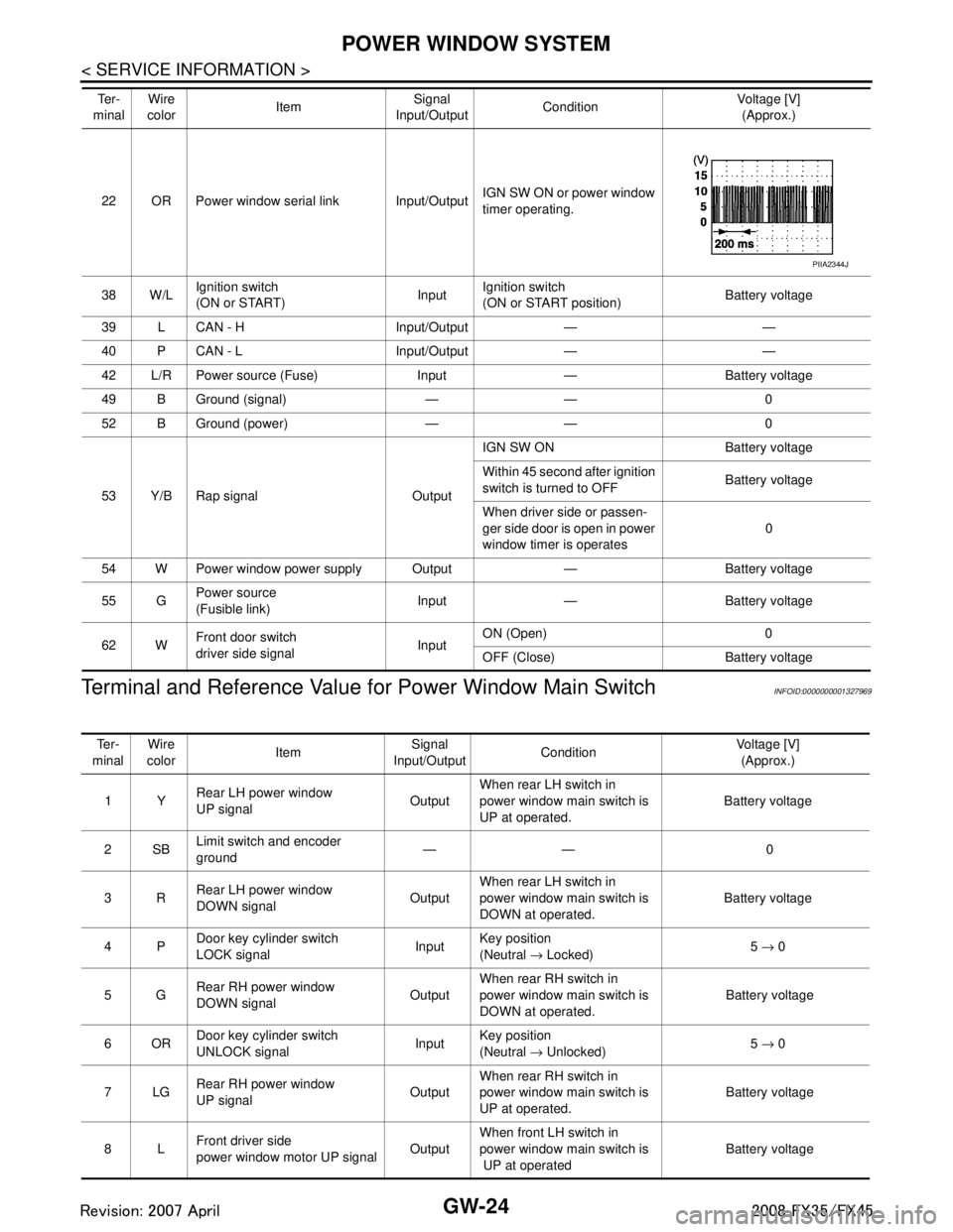
Terminal and Reference Value for Power Window Main Switch
INFOID:0000000001327969
22 OR Power window serial link Input/Output IGN SW ON or power window
timer operating.
38 W/L Ignition switch
(ON or START) InputIgnition switch
(ON or START position) Battery voltage
39 L CAN - H Input/Output — —
40 P CAN - L Input/Output — —
42 L/R Power source (Fuse) Input — Battery voltage
49 B Ground (signal) — — 0
52 B Ground (power) — — 0
53 Y/B Rap signal Output IGN SW ON Battery voltage
Within 45 second after ignition
switch is turned to OFF
Battery voltage
When driver side or passen-
ger side door is open in power
window timer is operates 0
54 W Power window power supply Output — Battery voltage
55 G Power source
(Fusible link)
Input — Battery voltage
62 W Front door switch
driver side signal InputON (Open) 0
OFF (Close) Battery voltage
Te r -
minal Wire
color Item Signal
Input/Output Condition Voltage [V]
(Approx.)
PIIA2344J
Te r -
minal Wire
color Item Signal
Input/Output Condition Voltage [V]
(Approx.)
1Y Rear LH power window
UP signal OutputWhen rear LH switch in
power window main switch is
UP at operated. Battery voltage
2SB Limit switch and encoder
ground —— 0
3R Rear LH power window
DOWN signal OutputWhen rear LH switch in
power window main switch is
DOWN at operated. Battery voltage
4P Door key cylinder switch
LOCK signal InputKey position
(Neutral
→ Locked) 5
→ 0
5G Rear RH power window
DOWN signal OutputWhen rear RH switch in
power window main switch is
DOWN at operated. Battery voltage
6OR Door key cylinder switch
UNLOCK signal Input
Key position
(Neutral
→ Unlocked) 5
→ 0
7LG Rear RH power window
UP signal OutputWhen rear RH switch in
power window main switch is
UP at operated. Battery voltage
8L Front driver side
power window motor UP signal
OutputWhen front LH switch in
power window main switch is
UP at operated
Battery voltage
3AA93ABC3ACD3AC03ACA3AC03AC63AC53A913A773A893A873A873A8E3A773A983AC73AC93AC03AC3
3A893A873A873A8F3A773A9D3AAF3A8A3A8C3A863A9D3AAF3A8B3A8C
Page 2938 of 3924
POWER WINDOW SYSTEMGW-25
< SERVICE INFORMATION >
C
DE
F
G H
J
K L
M A
B
GW
N
O P
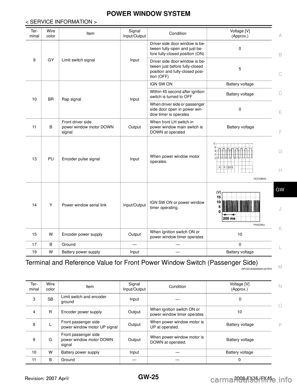
Terminal and Reference Value for Front Power Window Switch (Passenger Side)
INFOID:0000000001327970
9 GY Limit switch signal Input Driver side door window is be-
tween fully-open and just be-
fore fully-closed position (ON)
0
Driver side door window is be-
tween just before fully-closed
position and fully-closed posi-
tion (OFF) 5
10 BR Rap signal Input IGN SW ON Battery voltage
Within 45 second after ignition
switch is turned to OFF
Battery voltage
When driver side or passenger
side door open in power win-
dow timer is operates 0
11 B Front driver side
power window motor DOWN
signal Output
When front LH switch in
power window main switch is
DOWN at operated Battery voltage
13 PU Encoder pulse signal Input When power window motor
operates.
14 Y Power window serial link Input/Output IGN SW ON or power window
timer operating.
15 W Encoder power supply Output When ignition switch ON or
power window timer operates10
17 B Ground — — 0
19 W Battery power supply Input — Battery voltage
Te r -
minal Wire
color Item Signal
Input/Output Condition Voltage [V]
(Approx.)
OCC3383D
PIIA2344J
Te r -
minal Wire
color Item
Signal
Input/Output Condition
Voltage [V]
(Approx.)
3SB Limit switch and encoder
ground Input — 0
4 R Encoder power supply Output When ignition switch ON or
power window timer operates
10
8L Front passenger side
power window motor UP signal Output
When power window motor is
UP at operated. Battery voltage
9G Front passenger side
power window motor DOWN
signal Output
When power window motor is
DOWN at operated. Battery voltage
10 W Battery power supply Input — Battery voltage 11 B Ground — — 0
3AA93ABC3ACD3AC03ACA3AC03AC63AC53A913A773A893A873A873A8E3A773A983AC73AC93AC03AC3
3A893A873A873A8F3A773A9D3AAF3A8A3A8C3A863A9D3AAF3A8B3A8C
Page 2939 of 3924
GW-26
< SERVICE INFORMATION >
POWER WINDOW SYSTEM
CONSULT-III Function
INFOID:0000000001327971
ACTIVE TEST
WORK SUPPORT
DATE MONITOR
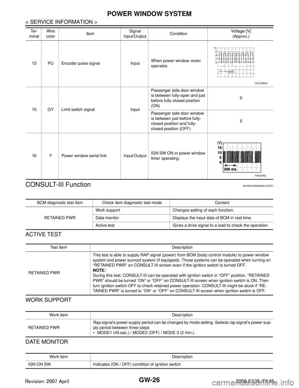
12 PU Encoder pulse signal Input When power window motor
operates.
15 GY Limit switch signal Input Passenger side door window
is between fully-open and just
before fully-closed position
(ON)
0
Passenger side door window
is between just before fully-
closed position and fully-
closed position (OFF) 5
16 Y Power window serial link Input/Output IGN SW ON or power window
timer operating.
Te r -
minal Wire
color Item Signal
Input/Output Condition Voltage [V]
(Approx.)
OCC3383D
PIIA2344J
BCM diagnostic test item Check item diagnostic test mode Content
RETAINED PWR Work support Changes setting of each function.
Data monitor Displays the input data of BCM in real time.
Active test Gives a drive signal to a load to check the operation.
Te s t I t e m D e s c r i p t i o n
RETAINED PWR This test is able to supply RAP signal (powe
r) from BCM (body control module) to power window
system and power sunroof system (if equipped). Those systems can be operated when turning on
“RETAINED PWR” on CONSULT-III screen even if the ignition switch is turned OFF.
NOTE:
During this test, CONSULT-III can be operated with ignition switch in “OFF” position. “RETAINED
PWR” should be turned “ON” or “OFF” on CONSULT-III screen when ignition switch is ON. Then
turn ignition switch OFF to check retained power operation. CONSULT-III might be stuck if “RE-
TAINED PWR” is turned to “ON” or “OFF” on CONSULT-III screen when ignition switch is OFF.
Work item Description
RETAINED PWR Rap signal’s power supply period can be changed by mode setting. Selects rap signal’s power sup-
ply period between three steps
MODE1 (45 sec.) / MODE2 (OFF) / MODE 3 (2 min.).
Work item Description
IGN ON SW Indicates (ON / OFF) condition of ignition switch
3AA93ABC3ACD3AC03ACA3AC03AC63AC53A913A773A893A873A873A8E3A773A983AC73AC93AC03AC3
3A893A873A873A8F3A773A9D3AAF3A8A3A8C3A863A9D3AAF3A8B3A8C
Page 2940 of 3924
POWER WINDOW SYSTEMGW-27
< SERVICE INFORMATION >
C
DE
F
G H
J
K L
M A
B
GW
N
O P
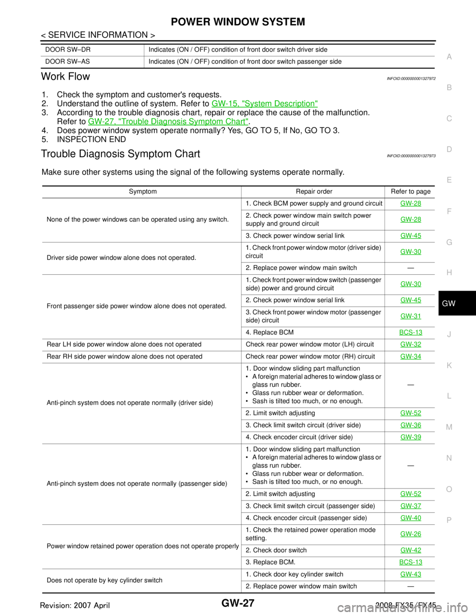
Work FlowINFOID:0000000001327972
1. Check the symptom and customer's requests.
2. Understand the outline of system. Refer to GW-15, "
System Description"
3. According to the trouble diagnosis chart, repa ir or replace the cause of the malfunction.
Refer to GW-27, "
Trouble Diagnosis Symptom Chart".
4. Does power window system operate normally ? Yes, GO TO 5, If No, GO TO 3.
5. INSPECTION END
Trouble Diagnosis Symptom ChartINFOID:0000000001327973
Make sure other systems using the signal of the following systems operate normally.
DOOR SW–DR Indicates (ON / OFF) condition of front door switch driver side
DOOR SW–AS Indicates (ON / OFF) condition of front door switch passenger side
Symptom Repair order Refer to page
None of the power windows can be operated using any switch. 1. Check BCM power supply and ground circuit
GW-28
2. Check power window main switch power
supply and ground circuitGW-28
3. Check power window serial link
GW-45
Driver side power window alone does not operated. 1. Check front power wind
ow motor (driver side)
circuit GW-30
2. Replace power window main switch —
Front passenger side power window alone does not operated. 1. Check front power window switch (passenger
side) power and ground circuit
GW-30
2. Check power window serial link
GW-45
3. Check front power window motor (passenger
side) circuitGW-31
4. Replace BCM
BCS-13
Rear LH side power window alone does not operated Check rear power window motor (LH) circuit GW-32
Rear RH side power window alone does not operated Check rear power window motor (RH) circuitGW-34
Anti-pinch system does not operate normally (driver side)1. Door window sliding part malfunction
A foreign material adheres to window glass or
glass run rubber.
Glass run rubber wear or deformation.
Sash is tilted too much, or no enough. —
2. Limit switch adjusting GW-52
3. Check limit switch circuit (driver side)GW-36
4. Check encoder circuit (driver side) GW-39
Anti-pinch system does not operate normally (passenger side) 1. Door window sliding part malfunction
A foreign material adheres to window glass or
glass run rubber.
Glass run rubber wear or deformation.
Sash is tilted too much, or no enough. —
2. Limit switch adjusting GW-52
3. Check limit switch circuit (passenger side)GW-37
4. Check encoder circuit (passenger side)GW-40
Power window retained power operation does not operate properly 1. Check the retained power operation mode
setting.
GW-262. Check door switch
GW-42
3. Replace BCM.BCS-13
Does not operate by key cylinder switch 1. Check door key cylinder switch
GW-432. Replace power window main switch —
3AA93ABC3ACD3AC03ACA3AC03AC63AC53A913A773A893A873A873A8E3A773A983AC73AC93AC03AC3
3A893A873A873A8F3A773A9D3AAF3A8A3A8C3A863A9D3AAF3A8B3A8C