2008 INFINITI FX35 power supply
[x] Cancel search: power supplyPage 3859 of 3924
TROUBLE DIAGNOSESWT-19
< SERVICE INFORMATION >
C
DF
G H
I
J
K L
M A
B
WT
N
O P
ID Registration ProcedureINFOID:0000000001327582
ID REGISTRATION WITH ACTIVATION TOOL
This procedure must be done after replacemen t of a transmitter, BCM or rotating wheels.
1. Touch “WORK SUPPORT” on “SELECT DIAG MODE” screen, and select “ID REGIST”.
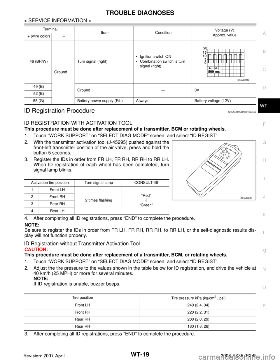
2. With the transmitter activati on tool (J-45295) pushed against the
front-left transmitter position of the air valve, press and hold the
button 5 seconds.
3. Register the IDs in order from FR LH, FR RH, RR RH to RR LH. When ID registration of each wheel has been completed, turn
signal lamp blinks.
4. After completing all ID registrations, press “END” to complete the procedure.
NOTE:
Be sure to register the IDs in order from FR LH, FR RH, RR RH, to RR LH, or the self-diagnostic results dis-
play will not function properly.
ID Registration without Tr ansmitter Activation Tool
CAUTION:
This procedure must be done after replacement of a transmitter, BCM, or rotating wheels.
1. Touch “WORK SUPPORT” on “SELECT DIAG MODE” screen, and select “ID REGIST”.
2. Adjust the tire pressure to the values shown in t he table below for ID registration, and drive the vehicle at
40 km/h (25 MPH) or more for several minutes.
NOTE:
If ID registration is unable, buzzer beeps.
3. After completing all ID registrations, press “END” to complete the procedure.
46 (BR/W) GroundTurn signal (right)
Ignition switch ON
Combination switch is turn
signal (right)
49 (B) Ground — 0V
52 (B)
55 (G) Battery power supply (F /L) Always Battery voltage (12V)
Te r m i n a l
Item Condition Voltage (V)
Approx. value
+ (wire color) –
SKIA3009J
Activation tire position Turn signal lamp CONSULT-IIII
1 Front LH
2 times flashing “Red”
↓
“Green”
2Front RH
3Rear RH
4 Rear LH
SEIA0460E
Tire position
Tire pressure kPa (kg/cm2 , psi)
Front LH 240 (2.4, 34)
Front RH 220 (2.2, 31) Rear RH 200 (2.0, 29)
Rear RH 180 (1.8, 26)
3AA93ABC3ACD3AC03ACA3AC03AC63AC53A913A773A893A873A873A8E3A773A983AC73AC93AC03AC3
3A893A873A873A8F3A773A9D3AAF3A8A3A8C3A863A9D3AAF3A8B3A8C
Page 3870 of 3924
WT-30
< SERVICE INFORMATION >
TROUBLE DIAGNOSIS FOR SYMPTOMS
TROUBLE DIAGNOSIS FOR SYMPTOMS
Low Tire Pressure Warning Lamp Does Not Come On When Ignition Switch Is Turned
On
INFOID:0000000001327593
DIAGNOSTIC PROCEDURE
1.CHECK SELF-DIAGNOSIS RESULTS
1. Select “SELF-DIAG RESULTS” on “SELECT DIAG MODE” screen.
2. Check display contents in self-diagnostic results.
Is
“CAN COMM CIRCUIT” displayed in the self-diagnosis display items?
YES >> Malfunction in CAN communication system. Go to LAN-43, "CAN System Specification Chart".
NO >> No malfunction. GO TO 2.
2.CHECK COMBINATION METER
Check combination meter function.
OK or NG
OK >> GO TO 3.
NG >> Check combination meter. Refer to DI-5, "
System Description".
3.CHECK LOW TIRE PRESSURE WARNING LAMP
Disconnect BCM harness connectors M3 and M4.
Does the warning lamp activate?
YES >> Replace BCM. Refer to BCS-13, "Removal and Installation of BCM".
NO >> Check combination meter and repair or replace.
Low Tire Pressure Warning Lamp Stays On When Ignition Switch Is Turned On
INFOID:0000000001327594
DIAGNOSTIC PROCEDURE
1.CHECK CONNECTOR
1. Disconnect BCM harness connectors M3 and M4.
2. Check terminals for damage or loose connections.
OK or NG
OK >> GO TO 2.
NG >> Repair or replace damaged parts.
2.CHECK POWER SUPPLY CIRCUIT (BATTERY)
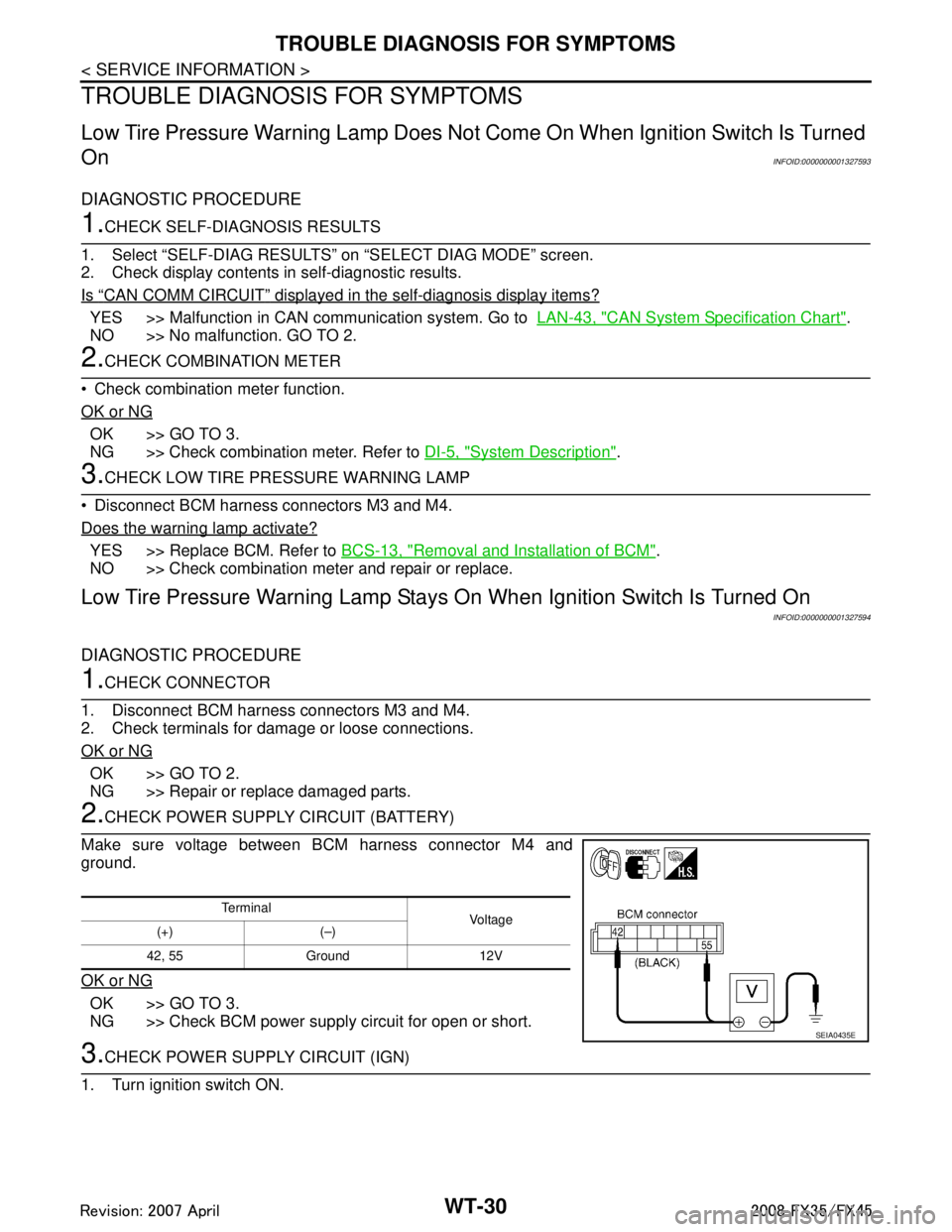
Make sure voltage between BCM harness connector M4 and
ground.
OK or NG
OK >> GO TO 3.
NG >> Check BCM power supply circuit for open or short.
3.CHECK POWER SUPPLY CIRCUIT (IGN)
1. Turn ignition switch ON.
Te r m i n a l Vol tag e
(+) (–)
42, 55 Ground 12V
SEIA0435E
3AA93ABC3ACD3AC03ACA3AC03AC63AC53A913A773A893A873A873A8E3A773A983AC73AC93AC03AC3
3A893A873A873A8F3A773A9D3AAF3A8A3A8C3A863A9D3AAF3A8B3A8C
Page 3871 of 3924
TROUBLE DIAGNOSIS FOR SYMPTOMSWT-31
< SERVICE INFORMATION >
C
DF
G H
I
J
K L
M A
B
WT
N
O P
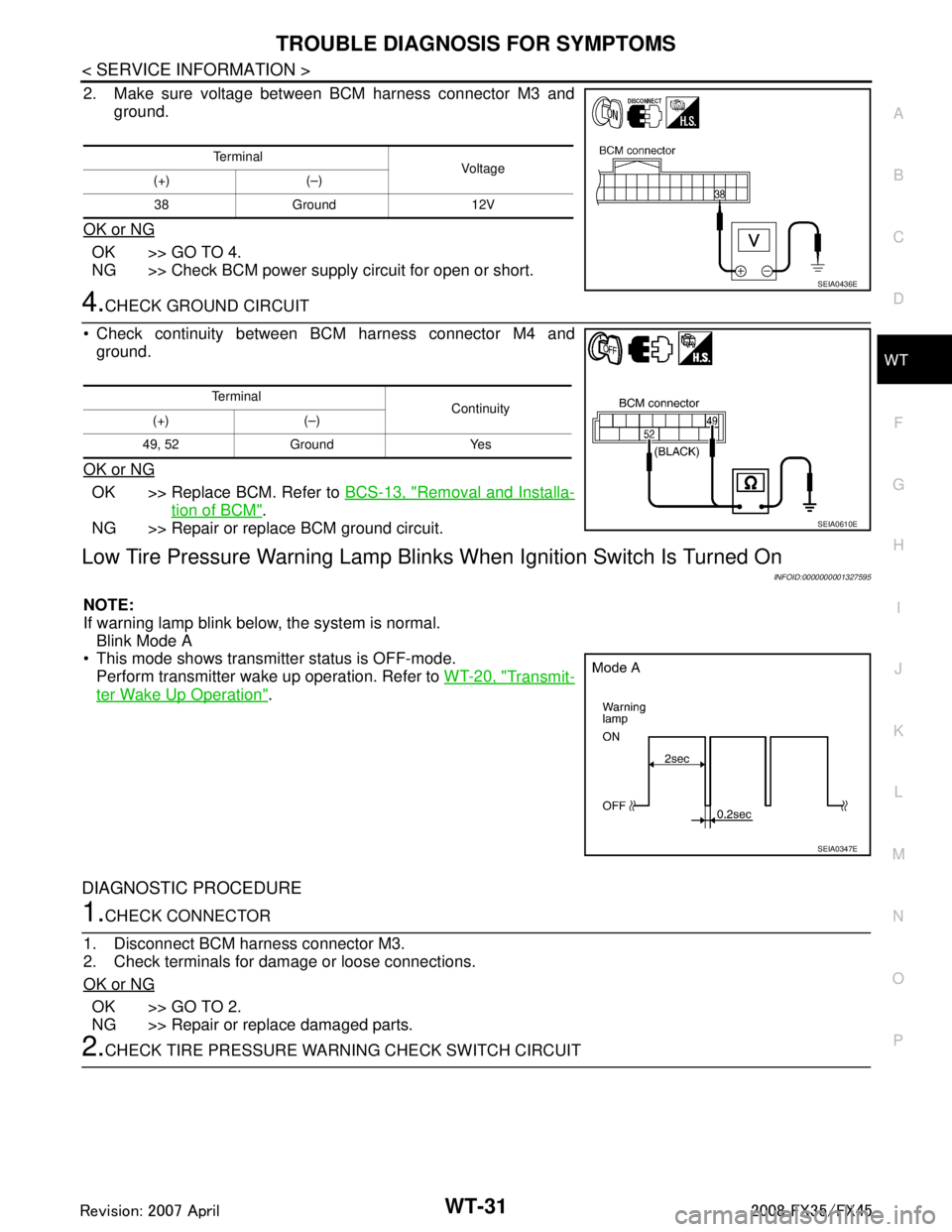
2. Make sure voltage between BCM harness connector M3 and ground.
OK or NG
OK >> GO TO 4.
NG >> Check BCM power supply circuit for open or short.
4.CHECK GROUND CIRCUIT
Check continuity between BCM harness connector M4 and ground.
OK or NG
OK >> Replace BCM. Refer to BCS-13, "Removal and Installa-
tion of BCM".
NG >> Repair or replace BCM ground circuit.
Low Tire Pressure Warning Lamp Blin ks When Ignition Switch Is Turned On
INFOID:0000000001327595
NOTE:
If warning lamp blink below, the system is normal.
Blink Mode A
This mode shows transmitter status is OFF-mode.
Perform transmitter wake up operation. Refer to WT-20, "
Transmit-
ter Wake Up Operation".
DIAGNOSTIC PROCEDURE
1.CHECK CONNECTOR
1. Disconnect BCM harness connector M3.
2. Check terminals for damage or loose connections.
OK or NG
OK >> GO TO 2.
NG >> Repair or replace damaged parts.
2.CHECK TIRE PRESSURE WA RNING CHECK SWITCH CIRCUIT
Te r m i n a l
Voltag e
(+) (–)
38 Ground 12V
SEIA0436E
Te r m i n a l Continuity
(+) (–)
49, 52 Ground Yes
SEIA0610E
SEIA0347E
3AA93ABC3ACD3AC03ACA3AC03AC63AC53A913A773A893A873A873A8E3A773A983AC73AC93AC03AC3
3A893A873A873A8F3A773A9D3AAF3A8A3A8C3A863A9D3AAF3A8B3A8C
Page 3888 of 3924
FRONT WIPER AND WASHER SYSTEMWW-13
< SERVICE INFORMATION >
C
DE
F
G H
I
J
L
M A
B
WW
N
O P
35 W/G Combination
switch output 2 ONLighting, turn,
wiper switch
(Wiper inter-
mittent dial
position 4) OFF
Approx. 7.2 V
Any of the conditions below
Front wiper switch INT
Front wiper switch HI Approx. 1.2 V
36 W/R Combination
switch output 1
ONLighting, turn,
wiper switch
(Wiper inter-
mittent dial
position 4) OFF
Approx. 7.2 V
Any of the conditions below
Front wiper switch MIST
Front wiper switch LO
Front washer switch Approx. 1.2 V
38 W/L Ignition switch
(ON) ON — Battery voltage
39 L CAN-H — — —
40 P CAN-L — — —
42 L/R Battery power
supply
OFF — Battery voltage
49 B Ground ON — Approx. 0 V
52 B Ground ON — Approx. 0 V
55 G Battery power
supply OFF — Battery voltage
Te r m i -
nal No. Wire
color Signal name Measuring condition
Reference value
Ignition
switch Operation or condition
PKIB4960J
PKIB4958J
PKIB4960J
PKIB4958J
3AA93ABC3ACD3AC03ACA3AC03AC63AC53A913A773A893A873A873A8E3A773A983AC73AC93AC03AC3
3A893A873A873A8F3A773A9D3AAF3A8A3A8C3A863A9D3AAF3A8B3A8C
Page 3889 of 3924
WW-14
< SERVICE INFORMATION >
FRONT WIPER AND WASHER SYSTEM
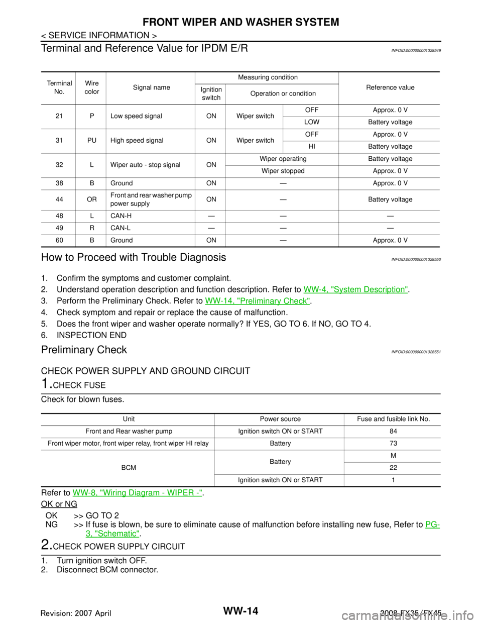
Terminal and Reference Value for IPDM E/R
INFOID:0000000001328549
How to Proceed with Trouble DiagnosisINFOID:0000000001328550
1. Confirm the symptoms and customer complaint.
2. Understand operation description and function description. Refer to WW-4, "
System Description".
3. Perform the Preliminary Check. Refer to WW-14, "
Preliminary Check".
4. Check symptom and repair or r eplace the cause of malfunction.
5. Does the front wiper and washer operate norma lly? If YES, GO TO 6. If NO, GO TO 4.
6. INSPECTION END
Preliminary CheckINFOID:0000000001328551
CHECK POWER SUPPLY AND GROUND CIRCUIT
1.CHECK FUSE
Check for blown fuses.
Refer to WW-8, "
Wiring Diagram - WIPER -".
OK or NG
OK >> GO TO 2
NG >> If fuse is blown, be sure to eliminate caus e of malfunction before installing new fuse, Refer to PG-
3, "Schematic".
2.CHECK POWER SUPPLY CIRCUIT
1. Turn ignition switch OFF.
2. Disconnect BCM connector.
Te r m i n a l No. Wire
color Signal name Measuring condition
Reference value
Ignition
switch Operation or condition
21 P Low speed signal ON Wiper switch OFF Approx. 0 V
LOW Battery voltage
31 PU High speed signal ON Wiper switch OFF Approx. 0 V
HI Battery voltage
32 L Wiper auto - stop signal ON Wiper operating Battery voltage
Wiper stopped Approx. 0 V
38 B Ground ON — Approx. 0 V
44 OR Front and rear washer pump
power supply ON — Battery voltage
48 L CAN-H — — —
49 R CAN-L — — —
60 B Ground ON — Approx. 0 V
Unit Power source Fuse and fusible link No.
Front and Rear washer pump Ignition switch ON or START 84
Front wiper motor, front wiper rela y, front wiper HI relay Battery 73
BCM BatteryM
22
Ignition switch ON or START 1
3AA93ABC3ACD3AC03ACA3AC03AC63AC53A913A773A893A873A873A8E3A773A983AC73AC93AC03AC3
3A893A873A873A8F3A773A9D3AAF3A8A3A8C3A863A9D3AAF3A8B3A8C
Page 3910 of 3924
REAR WIPER AND WASHER SYSTEMWW-35
< SERVICE INFORMATION >
C
DE
F
G H
I
J
L
M A
B
WW
N
O P
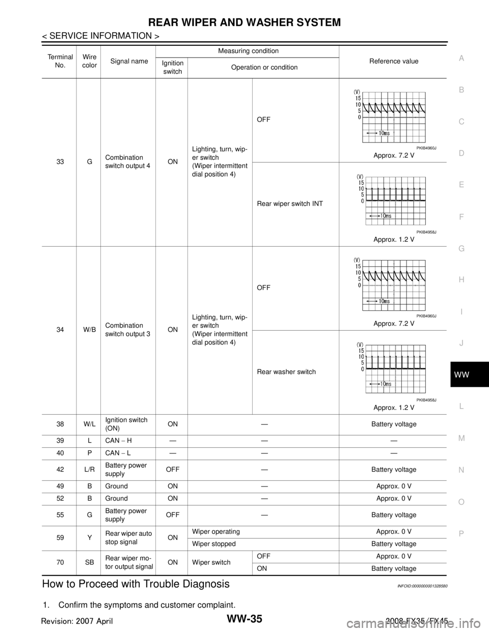
How to Proceed with Trouble DiagnosisINFOID:0000000001328580
1. Confirm the symptoms and customer complaint.
33 G Combination
switch output 4 ONLighting, turn, wip-
er switch
(Wiper intermittent
dial position 4) OFF
Approx. 7.2 V
Rear wiper switch INT Approx. 1.2 V
34 W/B Combination
switch output 3
ONLighting, turn, wip-
er switch
(Wiper intermittent
dial position 4) OFF
Approx. 7.2 V
Rear washer switch Approx. 1.2 V
38 W/L Ignition switch
(ON) ON — Battery voltage
39 L CAN − H— — —
40 P CAN − L— — —
42 L/R Battery power
supply
OFF — Battery voltage
49 B Ground ON — Approx. 0 V
52 B Ground ON — Approx. 0 V
55 G Battery power
supply OFF — Battery voltage
59 Y Rear wiper auto
stop signal
ONWiper operating Approx. 0 V
Wiper stopped Battery voltage
70 SB Rear wiper mo-
tor output signal ON Wiper switch OFF Approx. 0 V
ON Battery voltage
Te r m i n a l
No. Wire
color Signal name Measuring condition
Reference value
Ignition
switch Operation or condition
PKIB4960J
PKIB4958J
PKIB4960J
PKIB4958J
3AA93ABC3ACD3AC03ACA3AC03AC63AC53A913A773A893A873A873A8E3A773A983AC73AC93AC03AC3
3A893A873A873A8F3A773A9D3AAF3A8A3A8C3A863A9D3AAF3A8B3A8C
Page 3911 of 3924
WW-36
< SERVICE INFORMATION >
REAR WIPER AND WASHER SYSTEM
2. Understand operation description and function description. Refer to WW-30, "System Description".
3. Perform the Preliminary Check. Refer to WW-36, "
Preliminary Check".
4. Check symptom and repair or r eplace the cause of malfunction.
5. Does the rear wiper and washer operate no rmally? If YES, GO TO 6. If NO, GO TO 4.
6. INSPECTION END
Preliminary CheckINFOID:0000000001328581
CHECK POWER SUPPLY AND GROUND CIRCUIT
1.CHECK FUSES
Check for blown fuses.
Refer to WW-32, "Wiring Diagram - WIP/ R -".
OK or NG
OK >> GO TO 2.
NG >> If fuse is blown, be sure to eliminate caus e of malfunction before installing new fuse, Refer to PG-
3, "Schematic".
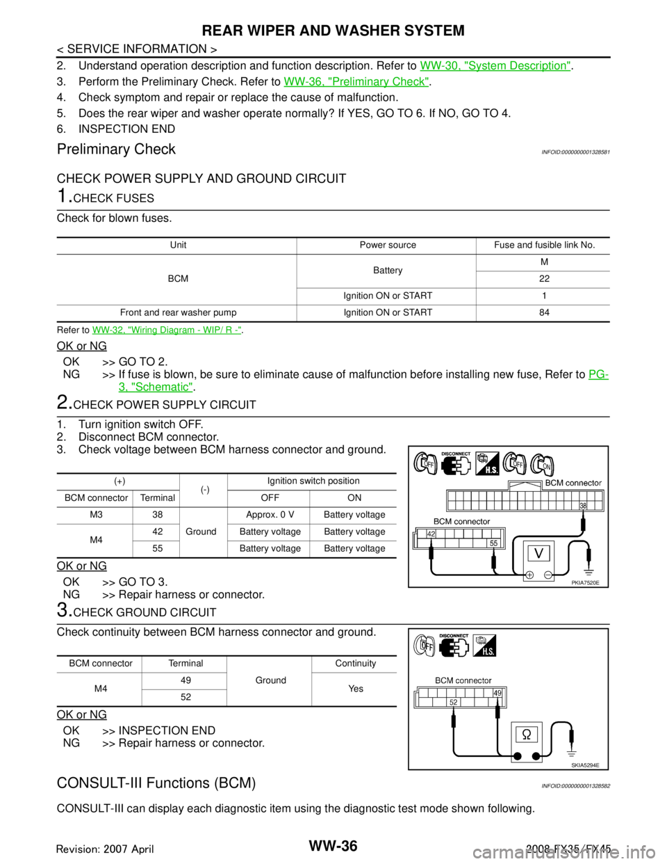
2.CHECK POWER SUPPLY CIRCUIT
1. Turn ignition switch OFF.
2. Disconnect BCM connector.
3. Check voltage between BCM harness connector and ground.
OK or NG
OK >> GO TO 3.
NG >> Repair harness or connector.
3.CHECK GROUND CIRCUIT
Check continuity between BCM harness connector and ground.
OK or NG
OK >> INSPECTION END
NG >> Repair harness or connector.
CONSULT-III Functions (BCM)INFOID:0000000001328582
CONSULT-III can display each diagnostic item using the diagnostic test mode shown following.
Unit Power source Fuse and fusible link No.
BCM BatteryM
22
Ignition ON or START 1
Front and rear washer pump Ignition ON or START 84
(+) (-)Ignition switch position
BCM connector Terminal OFF ON M3 38 GroundApprox. 0 V Battery voltage
M4 42 Battery voltage Battery voltage
55 Battery voltage Battery voltage
PKIA7520E
BCM connector Terminal
GroundContinuity
M4 49
Ye s
52
SKIA5294E
3AA93ABC3ACD3AC03ACA3AC03AC63AC53A913A773A893A873A873A8E3A773A983AC73AC93AC03AC3
3A893A873A873A8F3A773A9D3AAF3A8A3A8C3A863A9D3AAF3A8B3A8C