2008 INFINITI FX35 power supply
[x] Cancel search: power supplyPage 3715 of 3924

SE-76
< SERVICE INFORMATION >
AUTOMATIC DRIVE POSITIONER
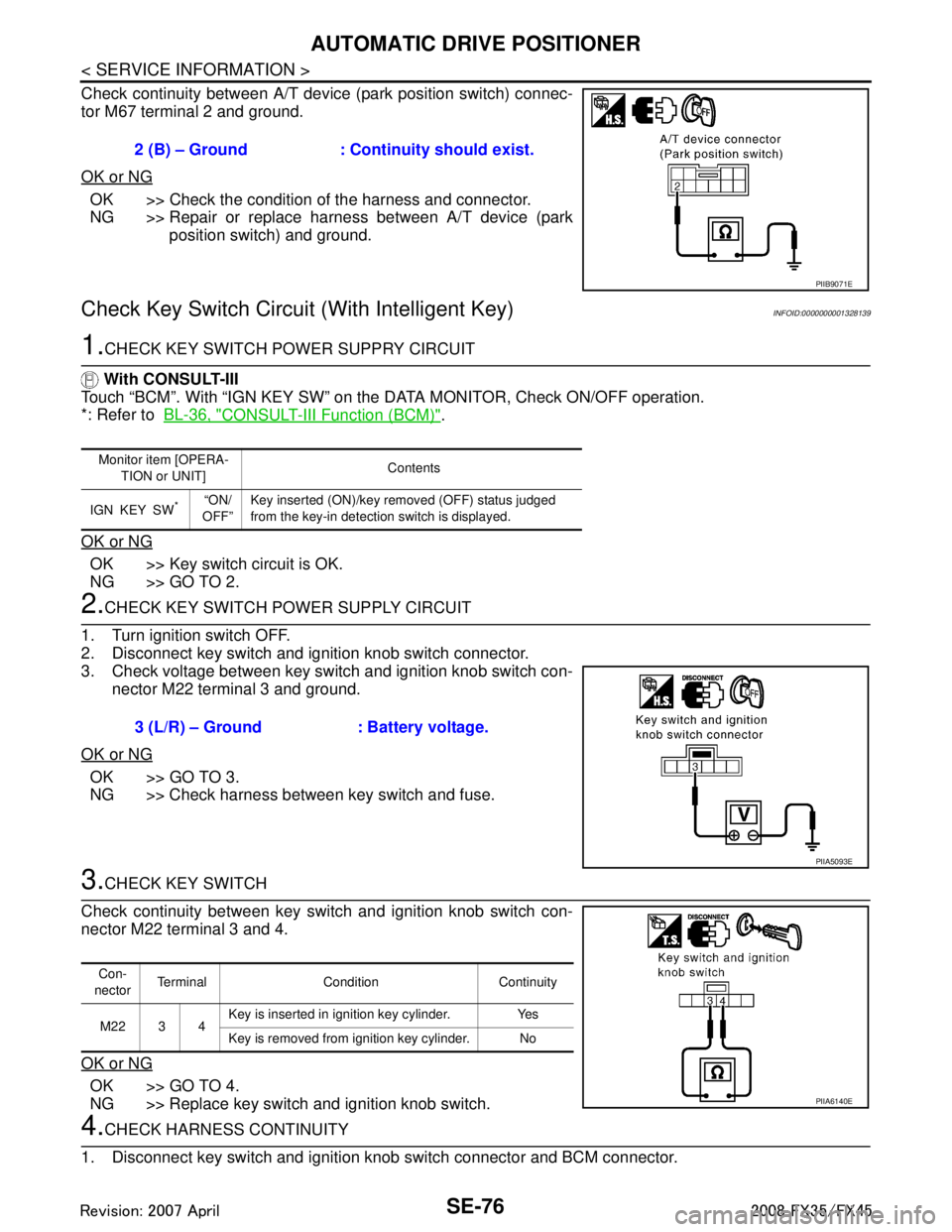
Check continuity between A/T device (park position switch) connec-
tor M67 terminal 2 and ground.
OK or NG
OK >> Check the condition of the harness and connector.
NG >> Repair or replace harness between A/T device (park position switch) and ground.
Check Key Switch Circuit (With Intelligent Key)INFOID:0000000001328139
1.CHECK KEY SWITCH POWER SUPPRY CIRCUIT
With CONSULT-III
Touch “BCM”. With “IGN KEY SW” on the DATA MONITOR, Check ON/OFF operation.
*: Refer to BL-36, "
CONSULT-III Function (BCM)".
OK or NG
OK >> Key switch circuit is OK.
NG >> GO TO 2.
2.CHECK KEY SWITCH PO WER SUPPLY CIRCUIT
1. Turn ignition switch OFF.
2. Disconnect key switch and ignition knob switch connector.
3. Check voltage between key switch and ignition knob switch con- nector M22 terminal 3 and ground.
OK or NG
OK >> GO TO 3.
NG >> Check harness between key switch and fuse.
3.CHECK KEY SWITCH
Check continuity between key switch and ignition knob switch con-
nector M22 terminal 3 and 4.
OK or NG
OK >> GO TO 4.
NG >> Replace key switch and ignition knob switch.
4.CHECK HARNESS CONTINUITY
1. Disconnect key switch and ignition knob switch connector and BCM connector. 2 (B) – Ground : Continuity should exist.
PIIB9071E
Monitor item [OPERA-
TION or UNIT] Contents
IGN KEY SW
*“ON/
OFF” Key inserted (ON)/key removed (OFF) status judged
from the key-in detection switch is displayed.
3 (L/R) – Ground : Battery voltage.
PIIA5093E
Con-
nector Terminal Condition Continuity
M22 3 4 Key is inserted in ignition key cylinder. Yes
Key is removed from ignition key cylinder. No
PIIA6140E
3AA93ABC3ACD3AC03ACA3AC03AC63AC53A913A773A893A873A873A8E3A773A983AC73AC93AC03AC3
3A893A873A873A8F3A773A9D3AAF3A8A3A8C3A863A9D3AAF3A8B3A8C
Page 3716 of 3924

AUTOMATIC DRIVE POSITIONERSE-77
< SERVICE INFORMATION >
C
DE
F
G H
J
K L
M A
B
SE
N
O P
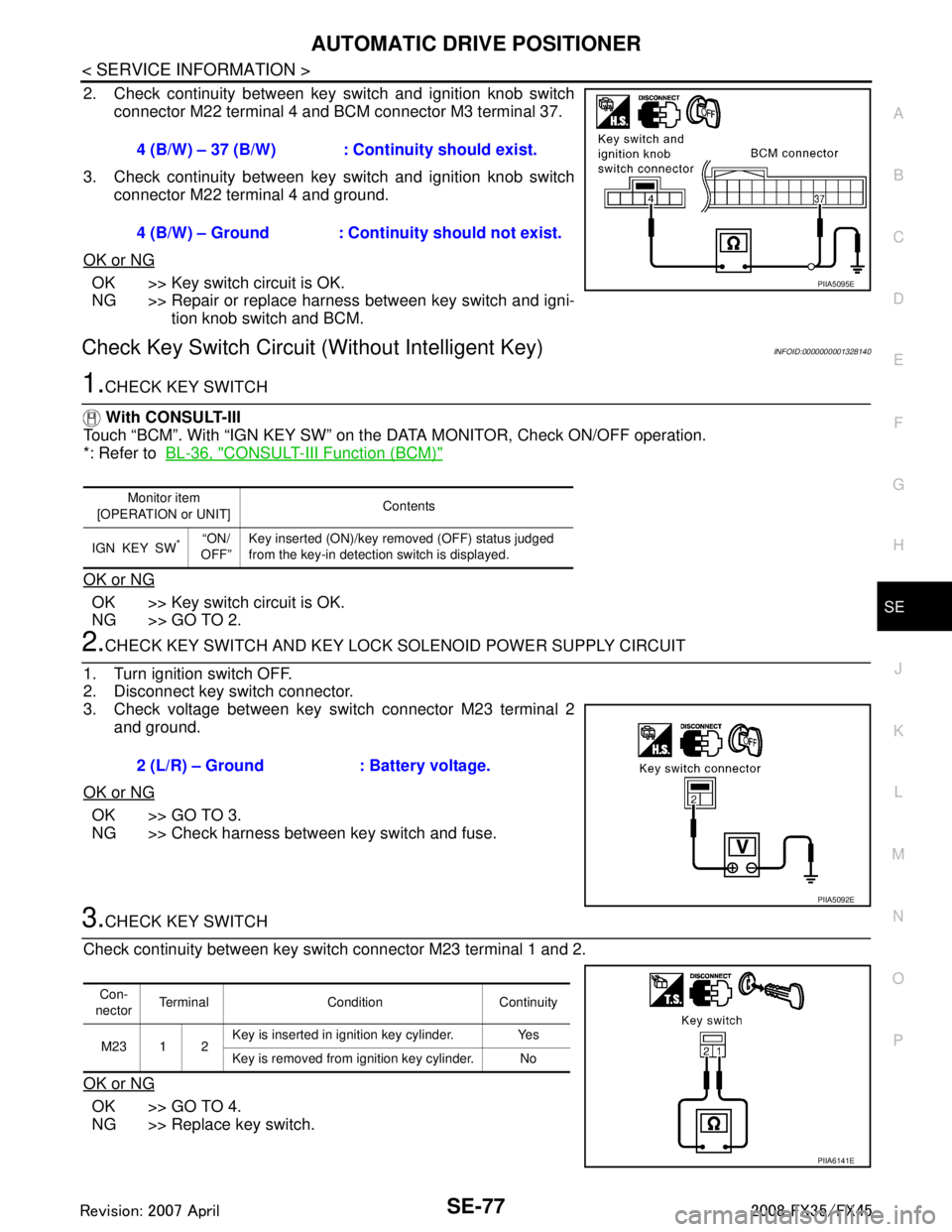
2. Check continuity between key switch and ignition knob switch connector M22 terminal 4 and BCM connector M3 terminal 37.
3. Check continuity between key switch and ignition knob switch connector M22 terminal 4 and ground.
OK or NG
OK >> Key switch circuit is OK.
NG >> Repair or replace harness between key switch and igni- tion knob switch and BCM.
Check Key Switch Circui t (Without Intelligent Key)INFOID:0000000001328140
1.CHECK KEY SWITCH
With CONSULT-III
Touch “BCM”. With “IGN KEY SW” on the DATA MONITOR, Check ON/OFF operation.
*: Refer to BL-36, "
CONSULT-III Function (BCM)"
OK or NG
OK >> Key switch circuit is OK.
NG >> GO TO 2.
2.CHECK KEY SWITCH AND KEY LOCK SOLENOID POWER SUPPLY CIRCUIT
1. Turn ignition switch OFF.
2. Disconnect key switch connector.
3. Check voltage between key switch connector M23 terminal 2 and ground.
OK or NG
OK >> GO TO 3.
NG >> Check harness between key switch and fuse.
3.CHECK KEY SWITCH
Check continuity between key switch connector M23 terminal 1 and 2.
OK or NG
OK >> GO TO 4.
NG >> Replace key switch. 4 (B/W) – 37 (B/W) : Cont
inuity should exist.
4 (B/W) – Ground : Continuity should not exist.
PIIA5095E
Monitor item
[OPERATION or UNIT] Contents
IGN KEY SW
*“ON/
OFF” Key inserted (ON)/key removed (OFF) status judged
from the key-in detection switch is displayed.
2 (L/R) – Ground : Battery voltage.
PIIA5092E
Con-
nector Terminal Condition Continuity
M23 1 2 Key is inserted in ignition key cylinder. Yes
Key is removed from ignition key cylinder. No
PIIA6141E
3AA93ABC3ACD3AC03ACA3AC03AC63AC53A913A773A893A873A873A8E3A773A983AC73AC93AC03AC3
3A893A873A873A8F3A773A9D3AAF3A8A3A8C3A863A9D3AAF3A8B3A8C
Page 3718 of 3924

AUTOMATIC DRIVE POSITIONERSE-79
< SERVICE INFORMATION >
C
DE
F
G H
J
K L
M A
B
SE
N
O P
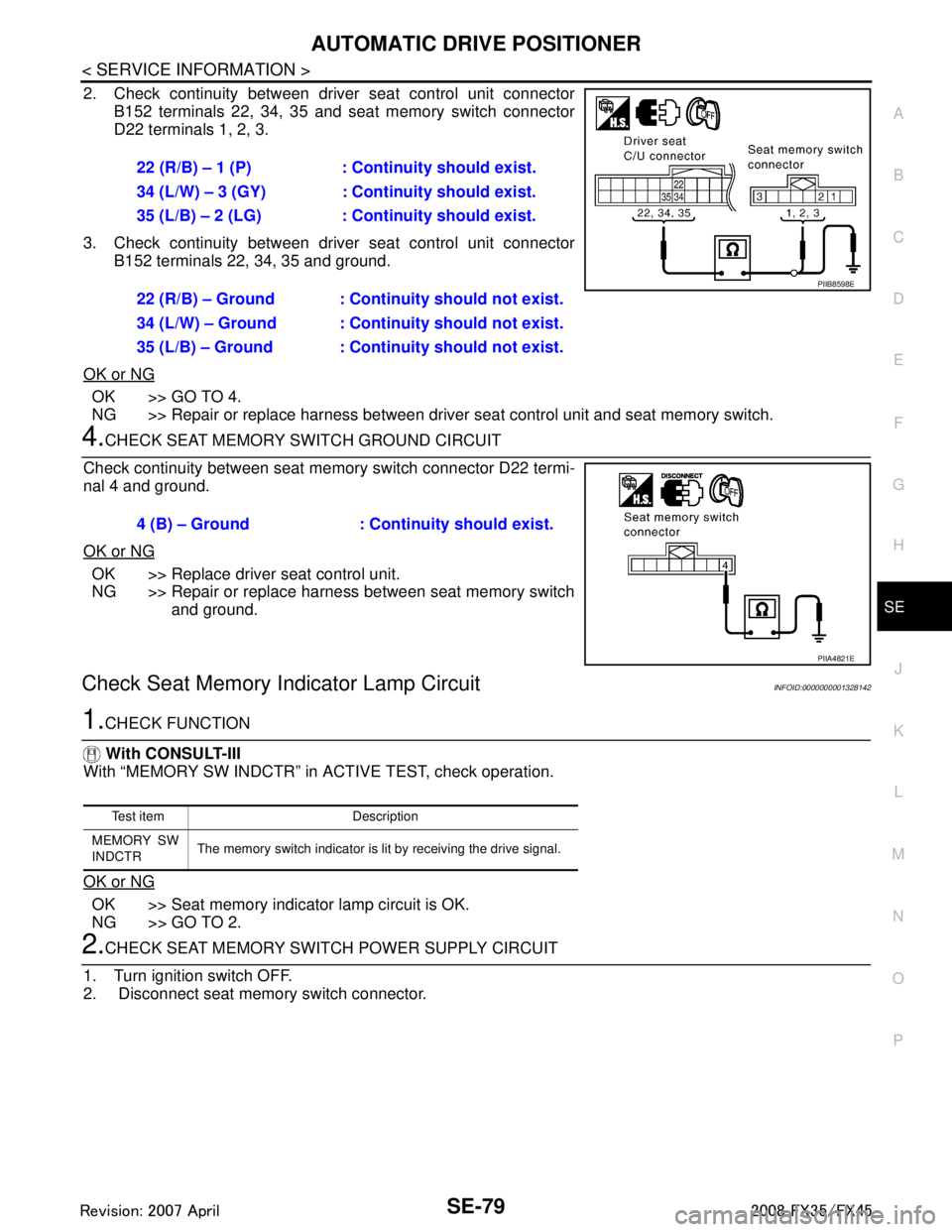
2. Check continuity between driver seat control unit connector B152 terminals 22, 34, 35 and seat memory switch connector
D22 terminals 1, 2, 3.
3. Check continuity between driver seat control unit connector B152 terminals 22, 34, 35 and ground.
OK or NG
OK >> GO TO 4.
NG >> Repair or replace harness between driver seat control unit and seat memory switch.
4.CHECK SEAT MEMORY SWITCH GROUND CIRCUIT
Check continuity between seat memory switch connector D22 termi-
nal 4 and ground.
OK or NG
OK >> Replace driver seat control unit.
NG >> Repair or replace harness between seat memory switch and ground.
Check Seat Memory I ndicator Lamp CircuitINFOID:0000000001328142
1.CHECK FUNCTION
With CONSULT-III
With “MEMORY SW INDCTR” in ACTIVE TEST, check operation.
OK or NG
OK >> Seat memory indicator lamp circuit is OK.
NG >> GO TO 2.
2.CHECK SEAT MEMORY SWITCH POWER SUPPLY CIRCUIT
1. Turn ignition switch OFF.
2. Disconnect seat memory switch connector. 22 (R/B) – 1 (P) : Continuity should exist.
34 (L/W) – 3 (GY) : Cont
inuity should exist.
35 (L/B) – 2 (LG) : Cont inuity should exist.
22 (R/B) – Ground : Continuity should not exist.
34 (L/W) – Ground : Continuity should not exist.
35 (L/B) – Ground : Continuity should not exist.
PIIB8598E
4 (B) – Ground : Continuity should exist.
PIIA4821E
Test item Description
MEMORY SW
INDCTR The memory switch indicator is lit by receiving the drive signal.
3AA93ABC3ACD3AC03ACA3AC03AC63AC53A913A773A893A873A873A8E3A773A983AC73AC93AC03AC3
3A893A873A873A8F3A773A9D3AAF3A8A3A8C3A863A9D3AAF3A8B3A8C
Page 3750 of 3924

TROUBLE DIAGNOSISSRS-13
< SERVICE INFORMATION >
C
DE
F
G
I
J
K L
M A
B
SRS
N
O P
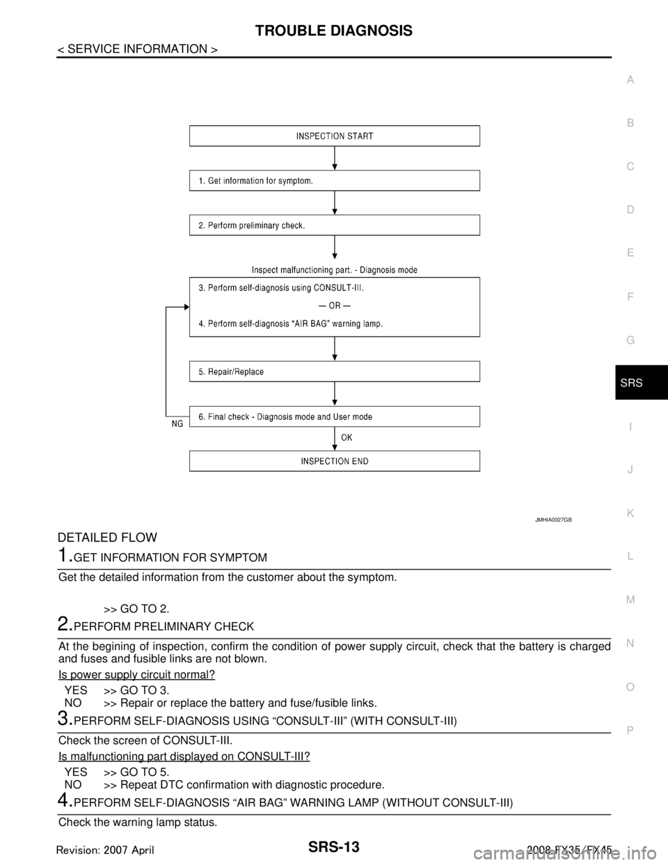
DETAILED FLOW
1.GET INFORMATION FOR SYMPTOM
Get the detailed information from the customer about the symptom.
>> GO TO 2.
2.PERFORM PRELIMINARY CHECK
At the begining of inspection, confirm the condition of pow er supply circuit, check that the battery is charged
and fuses and fusible links are not blown.
Is power supply circuit normal?
YES >> GO TO 3.
NO >> Repair or replace the battery and fuse/fusible links.
3.PERFORM SELF-DIAGNOSIS USING “C ONSULT-III” (WITH CONSULT-III)
Check the screen of CONSULT-III.
Is malfunctioning part displayed on CONSULT-III?
YES >> GO TO 5.
NO >> Repeat DTC confirmation with diagnostic procedure.
4.PERFORM SELF-DIAGNOSIS “AIR BAG” WA RNING LAMP (WITHOUT CONSULT-III)
Check the warning lamp status.
JMHIA0027GB
3AA93ABC3ACD3AC03ACA3AC03AC63AC53A913A773A893A873A873A8E3A773A983AC73AC93AC03AC3
3A893A873A873A8F3A773A9D3AAF3A8A3A8C3A863A9D3AAF3A8B3A8C
Page 3761 of 3924
![INFINITI FX35 2008 Service Manual
SRS-24
< SERVICE INFORMATION >
TROUBLE DIAGNOSIS
Trouble Diagnosis with CONSULT-III
INFOID:0000000001524168
DIAGNOSTIC PROCEDURE
DTC No. Index (“SELF-DIAG [ CURRENT]” “SELF-DIAG [PAST]” or INFINITI FX35 2008 Service Manual
SRS-24
< SERVICE INFORMATION >
TROUBLE DIAGNOSIS
Trouble Diagnosis with CONSULT-III
INFOID:0000000001524168
DIAGNOSTIC PROCEDURE
DTC No. Index (“SELF-DIAG [ CURRENT]” “SELF-DIAG [PAST]” or](/manual-img/42/57017/w960_57017-3760.png)
SRS-24
< SERVICE INFORMATION >
TROUBLE DIAGNOSIS
Trouble Diagnosis with CONSULT-III
INFOID:0000000001524168
DIAGNOSTIC PROCEDURE
DTC No. Index (“SELF-DIAG [ CURRENT]” “SELF-DIAG [PAST]” or TROUBLE DIAG RECORD)
Air bag is deployed.
Seat belt pre-tensioner is deployed. Go to
SRS-47, "For Frontal Colli-
sion" or SRS-48, "For Side Collision"
Diagnosis sensor unit is malfunction-
ing.
Air bag power supply circuit is mal-
functioning.
SRS air bag warning lamp circuit is malfunctioning. Go to
SRS-32, "
Trouble Diagnosis:
"AIR BAG" Warning Lamp Does Not
Turn OFF".
Diagnosis sensor unit is malfunction- ing.
Air bag warning lamp circuit is mal-
functioning. Go to
SRS-32, "
Trouble Diagnosis:
"AIR BAG" Warning Lamp Does Not
Turn ON".
“AIR BAG” warning lamp operation — User mode
—
SRS condition Reference item
SHIA0013E
SHIA0014E
Diagnostic mode Description
SELF-DIAG RESULT The self-d iagnosis result is Displayed. (SELF-DIAG [ CURRENT], [PAST], [RECORD])
ECU DISCRIMINATED No. The parts number of diagnosis sensor units displayed.
Diagnostic item Explanation Repair order
“Recheck SRS at each replacement”
NO DTC IS DETECT-
ED. When malfunction is in-
dicated by the “AIR
BAG” warning lamp in
User mode. Low battery voltage (Less than 9V)
Self-diagnostic result “SELF-DIAG
[PAST]” (previously stored in the
memory) might not be erased after re-
pair.
Intermittent malfunction has been de- tected in the past. Go to
SRS-21, "
CONSULT-III Func-
tion".
No malfunction is detected. —
DIAGNOSIS SENSOR
UNIT (CONTROL UNIT)
[B1001-B1015] Diagnosis sensor is out of order. Replace diagnosis sensor unit.
(ACU)
3AA93ABC3ACD3AC03ACA3AC03AC63AC53A913A773A893A873A873A8E3A773A983AC73AC93AC03AC3
3A893A873A873A8F3A773A9D3AAF3A8A3A8C3A863A9D3AAF3A8B3A8C
Page 3763 of 3924
![INFINITI FX35 2008 Service Manual
SRS-26
< SERVICE INFORMATION >
TROUBLE DIAGNOSIS
DRIVER AIR BAG
MODULE
[OPEN]
[B1049] [B1054] Driver air bag module circuit is open (including the spiral cable). 1. Visually check the wiring harnes INFINITI FX35 2008 Service Manual
SRS-26
< SERVICE INFORMATION >
TROUBLE DIAGNOSIS
DRIVER AIR BAG
MODULE
[OPEN]
[B1049] [B1054] Driver air bag module circuit is open (including the spiral cable). 1. Visually check the wiring harnes](/manual-img/42/57017/w960_57017-3762.png)
SRS-26
< SERVICE INFORMATION >
TROUBLE DIAGNOSIS
DRIVER AIR BAG
MODULE
[OPEN]
[B1049] [B1054] Driver air bag module circuit is open (including the spiral cable). 1. Visually check the wiring harness
connection.
2. Replace the harness if it has visi- ble damage.
3. Replace driver air bag module.
4. Replace spiral cable.
5. Replace diagnosis sensor unit (ACU).
DRIVER AIR BAG
MODULE
[VB-SHORT]
[B1050] [B1055] Driver air bag module circuit is shorted to a power supply circuit
(including the spiral cable).
DRIVER AIR BAG
MODULE
[GND-SHORT]
[B1051] [B1056] Driver air bag module circuit is shorted to ground (including the
spiral cable).
DRIVER AIR BAG
MODULE
[SHORT]
[B1052] [B1057] Driver air bag module circuit is shorted between lines.
DIAGNOSIS SENSOR
UNIT (CONTROL UNIT)
[B1058-B1063] Diagnosis sensor is out of order. Replace diagnosis sensor unit.
(ACU)
ASSIST A/B MODULE
[OPEN]
[B1065] [B1070] Front passenger air bag module circuit is open. 1. Visually check the wiring harness
connection.
2. Replace the harness if it has visi- ble damage.
3. Replace front passenger air bag
module.
4. Replace diagnosis sensor unit (ACU).
ASSIST A/B MODULE
[VB-SHORT]
[B1066] [B1071]
Front passenger air bag module circuit is shorted to a power sup-
ply circuit.
ASSIST A/B MODULE
[GND-SHORT]
[B1067] [B1072] Front passenger air bag module circuit is shorted to ground.
ASSIST A/B MODULE
[SHORT]
[B1068] [B1073] Front passenger air bag module circuit is shorted between lines.
DIAGNOSIS SENSOR
UNIT (CONTROL UNIT)
[B1074-B1079] Diagnosis sensor is out of order. Replace diagnosis sensor unit.
(ACU)
PRE-TEN FRONT RH
[OPEN]
[B1081] Front RH pre-tensioner circuit is open. 1. Visually check the wiring harness
connections.
2. Replace the harness if it has visi- ble damage.
3. Replace front RH seat belt.
4. Replace diagnosis sensor unit
(ACU).
PRE-TEN FRONT RH
[VB-SHORT]
[B1082]
Front RH pre-tensioner circuit is shorted to a power supply cir-
cuit.
PRE-TEN FRONT RH
[GND-SHORT]
[B1083] Front RH pre-tensioner circuit is shorted to ground.
PRE-TEN FRONT RH
[SHORT]
[B1084] Front RH pre-tensioner circuit is shorted between lines.
Diagnostic item Explanation
Repair order
“Recheck SRS at each replacement”
3AA93ABC3ACD3AC03ACA3AC03AC63AC53A913A773A893A873A873A8E3A773A983AC73AC93AC03AC3
3A893A873A873A8F3A773A9D3AAF3A8A3A8C3A863A9D3AAF3A8B3A8C
Page 3764 of 3924
![INFINITI FX35 2008 Service Manual
TROUBLE DIAGNOSISSRS-27
< SERVICE INFORMATION >
C
DE
F
G
I
J
K L
M A
B
SRS
N
O P
PRE-TEN FRONT LH
[OPEN]
[B1086] Front LH pre-tensioner circuit is open. 1. Visually check the wiring harness
conne INFINITI FX35 2008 Service Manual
TROUBLE DIAGNOSISSRS-27
< SERVICE INFORMATION >
C
DE
F
G
I
J
K L
M A
B
SRS
N
O P
PRE-TEN FRONT LH
[OPEN]
[B1086] Front LH pre-tensioner circuit is open. 1. Visually check the wiring harness
conne](/manual-img/42/57017/w960_57017-3763.png)
TROUBLE DIAGNOSISSRS-27
< SERVICE INFORMATION >
C
DE
F
G
I
J
K L
M A
B
SRS
N
O P
PRE-TEN FRONT LH
[OPEN]
[B1086] Front LH pre-tensioner circuit is open. 1. Visually check the wiring harness
connections.
2. Replace the harness if it has visi- ble damage.
3. Replace the front LH seat belt.
4. Replace the diagnosis sensor unit.
5. Replace the related harness.
PRE-TEN FRONT LH
[VB-SHORT]
[B1087]
Front LH pre-tensioner circuit is shorted to a power supply cir-
cuit.
PRE-TEN FRONT LH
[GND-SHORT]
[B1088] Front LH pre-tensioner circuit is shorted to ground.
PRE-TEN FRONT LH
[SHORT]
[B1089] Front LH pre-tensioner circuit is shorted between lines.
DIAGNOSIS SENSOR
UNIT (CONTROL UNIT)
[ B 11 0 6 - B 1111 ] Diagnosis sensor is out of order. Replace diagnosis sensor unit
(ACU).
SATELLITE SENS RH
[UNIT FAIL]
[ B 111 3 ] [ B 111 4 ]
SATELLITE SENS RH
[COMM FAIL]
[ B 111 5 ] RH side air bag (Satellite) sensor 1. Visually check the wiring harness
connection.
2. Replace the harness if it has visi-
ble damage.
3. Replace RH side air bag (Satel- lite) sensor.
4. Replace diagnosis sensor unit (ACU).
SATELLITE SENS LH
[UNIT FAIL]
[ B 111 8 ] [ B 111 9 ]
SATELLITE SENS LH
[COMM FAIL]
[B1120] LH side air bag (Satellite) sensor 1. Visually check the wiring harness
connection.
2. Replace the harness if it has visi- ble damage.
3. Replace LH side air bag (Satel-
lite) sensor.
4. Replace diagnosis sensor unit (ACU).
DIAGNOSIS SENSOR
UNIT (CONTROL UNIT)
[ B 11 2 2 - B 11 2 7 ] Diagnosis sensor is out of order. Replace diagnosis sensor unit
(ACU).
SIDE MODULE RH
[OPEN]
[B1129] Front RH side air bag module circuit is open. 1. Visually check the wiring harness
connection.
2. Replace the harness if it has visi- ble damage.
3. Replace front RH side air bag module.
4. Replace diagnosis sensor unit (ACU).
SIDE MODULE RH
[VB-SHORT]
[B1130]
Front RH side air bag module circuit is shorted to a power supply
circuit.
SIDE MODULE RH
[GND-SHORT]
[B1131] Front RH side air bag module circuit is shorted to ground.
SIDE MODULE RH
[SHORT]
[B1132] Front RH side air bag module circuit is shorted between lines.
Diagnostic item Explanation
Repair order
“Recheck SRS at each replacement”
3AA93ABC3ACD3AC03ACA3AC03AC63AC53A913A773A893A873A873A8E3A773A983AC73AC93AC03AC3
3A893A873A873A8F3A773A9D3AAF3A8A3A8C3A863A9D3AAF3A8B3A8C
Page 3765 of 3924

SRS-28
< SERVICE INFORMATION >
TROUBLE DIAGNOSIS
NOTE:
Follow the procedures in numerical order when repairing malfunctioning parts. Confirm whether malfunction is
eliminated using air bag warning lamp or CONSULT-III eac h time repair is finished. If malfunction is still
observed, proceed to the next step. When malfunction is eliminated, further repair work is not required.
Trouble Diagnosis without CONSULT-IIIINFOID:0000000001524169
DIAGNOSTIC PROCEDURE
SIDE MODULE LH
[OPEN]
[B1134] Front LH side air bag module circuit is open. 1. Visually check the wiring harness
connection.
2. Replace the harness if it has visi- ble damage.
3. Replace front LH side air bag module.
4. Replace diagnosis sensor unit
(ACU).
SIDE MODULE LH
[VB-SHORT]
[B1135]
Front LH side air bag module circuit is shorted to a power supply
circuit.
SIDE MODULE LH
[GND-SHORT]
[B1136] Front LH side air bag module circuit is shorted to ground.
SIDE MODULE LH
[SHORT]
[B1137] Front LH side air bag module circuit is shorted between lines.
DIAGNOSIS SENSOR
UNIT (CONTROL UNIT)
[ B 11 3 8 - B 11 4 3 ] Diagnosis sensor is out of order. Replace diagnosis sensor unit
(ACU).
CURTAIN MODULE RH
[OPEN]
[B1145] RH side curtain air bag module circuit is open. 1. Visually check the wiring harness
connection.
2. Replace the harness if it has visi-
ble damage.
3. Replace RH side curtain air bag module.
4. Replace diagnosis sensor unit (ACU).
CURTAIN MODULE RH
[VB-SHORT]
[B1146]
RH side curtain air bag module circuit is shorted to a power sup-
ply circuit.
CURTAIN MODULE RH
[GND-SHORT]
[B1147] RH side curtain air bag module circuit is shorted to ground.
CURTAIN MODULE RH
[SHORT]
[B1148] RH side curtain air bag module circuit is shorted between lines.
CURTAIN MODULE LH
[OPEN]
[B1150] LH side curtain air bag module circuit is open. 1. Visually check the wiring harness
connection.
2. Replace the harness if it has visi- ble damage.
3. Replace LH side curtain air bag module.
4. Replace diagnosis sensor unit
(ACU).
CURTAIN MODULE LH
[VB-SHORT]
[B1151]
LH side curtain air bag module circuit is shorted to a power sup-
ply circuit.
CURTAIN MODULE LH
[GND-SHORT]
[B1152] LH side curtain air bag module circuit is shorted to ground.
CURTAIN MODULE LH
[SHORT]
[B1153] LH side curtain air bag module circuit is shorted between lines.
DIAGNOSIS SENSOR
UNIT (CONTROL UNIT)
[B1202-B1207] Diagnosis sensor is out of order. Replace diagnosis sensor unit.
FRONTAL COLLISION-
DETECTION
[B1209] Seat belt pre-tensioner and front air bag are deployed. Go to
SRS-47, "
For Frontal Colli-
sion".
SIDE COLLISION DE-
TECTION
[B1210] Side and curtain air bag is deployed. Go to
SRS-48, "
For Side Collision".
Diagnostic item Explanation
Repair order
“Recheck SRS at each replacement”
3AA93ABC3ACD3AC03ACA3AC03AC63AC53A913A773A893A873A873A8E3A773A983AC73AC93AC03AC3
3A893A873A873A8F3A773A9D3AAF3A8A3A8C3A863A9D3AAF3A8B3A8C