2008 INFINITI FX35 power supply
[x] Cancel search: power supplyPage 3099 of 3924
![INFINITI FX35 2008 Service Manual
TROUBLE DIAGNOSISLAN-79
< SERVICE INFORMATION > [CAN]
C
D
E
F
G H
I
J
L
M A
B
LAN
N
O P
OK >> GO TO 3.
NG >> Repair the ABS actuator and electric unit (control unit) branch line.
3.CHECK POWER SUPPLY INFINITI FX35 2008 Service Manual
TROUBLE DIAGNOSISLAN-79
< SERVICE INFORMATION > [CAN]
C
D
E
F
G H
I
J
L
M A
B
LAN
N
O P
OK >> GO TO 3.
NG >> Repair the ABS actuator and electric unit (control unit) branch line.
3.CHECK POWER SUPPLY](/manual-img/42/57017/w960_57017-3098.png)
TROUBLE DIAGNOSISLAN-79
< SERVICE INFORMATION > [CAN]
C
D
E
F
G H
I
J
L
M A
B
LAN
N
O P
OK >> GO TO 3.
NG >> Repair the ABS actuator and electric unit (control unit) branch line.
3.CHECK POWER SUPPLY AND GROUND CIRCUIT
Check the power supply and the ground circuit of the A BS actuator and electric unit (control unit). Refer to
BRC-17, "
Schematic".
OK or NG
OK >> Present error: Replace the ABS actuator and electric unit (control unit). Refer to BRC-54,
"Removal and Installation".
Past error: Error was detected in the ABS act uator and electric unit (control unit) branch line.
NG >> Repair the power supply and the ground circuit.
ICC Sensor Branch Line CircuitINFOID:0000000001328666
INSPECTION PROCEDURE
1.CHECK CONNECTOR
1. Turn the ignition switch OFF.
2. Disconnect the battery cabl e from the negative terminal.
3. Check the terminals and connectors of the ICC s ensor for damage, bend and loose connection (unit side
and connector side).
OK or NG
OK >> GO TO 2.
NG >> Repair the terminal and connector.
2.CHECK HARNESS FOR OPEN CIRCUIT
1. Disconnect the connector of ICC sensor.
2. Check the resistance between the I CC sensor harness connector terminals.
OK or NG
OK >> GO TO 3.
NG >> Repair the ICC sensor branch line.
3.CHECK POWER SUPPLY AND GROUND CIRCUIT
Check the power supply and the ground circuit of the ICC sensor. Refer to ACS-19, "
Schematic".
OK or NG
OK >> Present error: Replace the ICC sensor. Refer to ACS-65, "ICC Sensor".
Past error: Error was detected in the ICC sensor branch line.
NG >> Repair the power supply and the ground circuit.
Driver Seat Control Un it Branch Line CircuitINFOID:0000000001328667
INSPECTION PROCEDURE
1.CHECK CONNECTOR
1. Turn the ignition switch OFF.
2. Disconnect the battery cabl e from the negative terminal.
3. Check the following terminals and connectors for damage, bend and loose connection (unit side and con-
nector side).
- Driver seat control unit
- Harness connector B151
- Harness connector B8
OK or NG
OK >> GO TO 2.
NG >> Repair the terminal and connector.
ICC sensor harness connector Resistance (Ω)
Connector No. Terminal No.
E39 3 6 Approx. 54 – 66
3AA93ABC3ACD3AC03ACA3AC03AC63AC53A913A773A893A873A873A8E3A773A983AC73AC93AC03AC3
3A893A873A873A8F3A773A9D3AAF3A8A3A8C3A863A9D3AAF3A8B3A8C
Page 3100 of 3924
![INFINITI FX35 2008 Service Manual
LAN-80
< SERVICE INFORMATION >[CAN]
TROUBLE DIAGNOSIS
2.CHECK HARNESS FOR OPEN CIRCUIT
1. Disconnect the connector of driver seat control unit.
2. Check the resistance between the driver seat contro INFINITI FX35 2008 Service Manual
LAN-80
< SERVICE INFORMATION >[CAN]
TROUBLE DIAGNOSIS
2.CHECK HARNESS FOR OPEN CIRCUIT
1. Disconnect the connector of driver seat control unit.
2. Check the resistance between the driver seat contro](/manual-img/42/57017/w960_57017-3099.png)
LAN-80
< SERVICE INFORMATION >[CAN]
TROUBLE DIAGNOSIS
2.CHECK HARNESS FOR OPEN CIRCUIT
1. Disconnect the connector of driver seat control unit.
2. Check the resistance between the driver seat control unit harness connector terminals.
OK or NG
OK >> GO TO 3.
NG >> Repair the driver seat control unit branch line.
3.CHECK POWER SUPPLY AND GROUND CIRCUIT
Check the power supply and the ground circuit of the driver seat control unit. Refer to SE-18, "
Schematic".
OK or NG
OK >> Present error: Replace the driver seat control unit. Refer to SE-16, "Component Parts and Har-
ness Connector Location".
Past error: Error was detected in t he driver seat control unit branch line.
NG >> Repair the power supply and the ground circuit.
IPDM E/R Branch Line CircuitINFOID:0000000001328668
INSPECTION PROCEDURE
1.CHECK CONNECTOR
1. Turn the ignition switch OFF.
2. Disconnect the battery cable from the negative terminal.
3. Check the following terminals and connectors fo r damage, bend and loose connection (unit side and con-
nector side).
- IPDM E/R
- Harness connector E205
- Harness connector B5
OK or NG
OK >> GO TO 2.
NG >> Repair the terminal and connector.
2.CHECK HARNESS FOR OPEN CIRCUIT
1. Disconnect the connector of IPDM E/R.
2. Check the resistance between the IPDM E/R harness connector terminals.
OK or NG
OK >> GO TO 3.
NG >> Repair the IPDM E/R branch line.
3.CHECK POWER SUPPLY AND GROUND CIRCUIT
Check the power supply and the ground circuit of the IPDM E/R. Refer to PG-23, "
IPDM E/R Power/Ground
Circuit Inspection".
OK or NG
OK >> Present error: Replace the IPDM E/R. Refer to PG-24, "Removal and Installation of IPDM E/R".
Past error: Error was detected in the IPDM E/R branch line.
NG >> Repair the power supply and the ground circuit.
Driver seat control unit harness connector Resistance (Ω)
Connector No. Terminal No.
B152 14 15 Approx. 54 – 66
IPDM E/R harness connector Resistance (Ω)
Connector No. Terminal No.
E9 48 49 Approx. 108 – 132
3AA93ABC3ACD3AC03ACA3AC03AC63AC53A913A773A893A873A873A8E3A773A983AC73AC93AC03AC3
3A893A873A873A8F3A773A9D3AAF3A8A3A8C3A863A9D3AAF3A8B3A8C
Page 3109 of 3924
HEADLAMP - XENON TYPE -LT-7
< SERVICE INFORMATION >
C
DE
F
G H
I
J
L
M A
B
LT
N
O P
Exterior lamp battery saver control mode can be changed by the function setting of CONSULT-III.
AUTO LIGHT OPERATION (IF EQUIPPED)
Refer to LT-47, "System Description".
VEHICLE SECURITY SYSTEM
The vehicle security system will flash the high beams if the system is triggered. Refer to BL-163.
XENON HEADLAMP
Xenon type lamps are used for to the low beam headlamps . Xenon bulbs do not use a filament. Instead, they
produce light when a high voltage current is passed between two tungsten electrodes through a mixture of
xenon (an inert gas) and certain other metal halides. In addition to strong lighting power, electronic control of
the power supply gives the headlamps stable quality and tone color.
Followings are some advantages of the xenon type headlamp.
The light produced by the headlamps is white color si milar to sunlight that is easy to the eyes.
Light output is nearly double that of halogen headl amps, affording increased area of illumination.
Counter-reflected luminance increases and the contrast enhances on the wet road in the rain. That makes
visibility go up more than the increase of the light volume.
Power consumption is approximately 25 percent less than halogen headlamps, reducing battery load.
CAN Communication System DescriptionINFOID:0000000001328267
CAN (Controller Area Network) is a serial communication li ne for real time application. It is an on-vehicle mul-
tiplex communication line with high data communication speed and excellent error detection ability. Many elec-
tronic control units are equipped onto a vehicle, and each control unit shares information and links with other
control units during operation (not independent). In CAN communication, control units are connected with 2
communication lines (CAN H line, CAN L line) allowing a high rate of information transmission with less wiring.
Each control unit transmits/receives data but selectively reads required data only.
CAN Communication UnitINFOID:0000000001328268
Refer to LAN-43, "CAN System Specification Chart".
3AA93ABC3ACD3AC03ACA3AC03AC63AC53A913A773A893A873A873A8E3A773A983AC73AC93AC03AC3
3A893A873A873A8F3A773A9D3AAF3A8A3A8C3A863A9D3AAF3A8B3A8C
Page 3116 of 3924
LT-14
< SERVICE INFORMATION >
HEADLAMP - XENON TYPE -
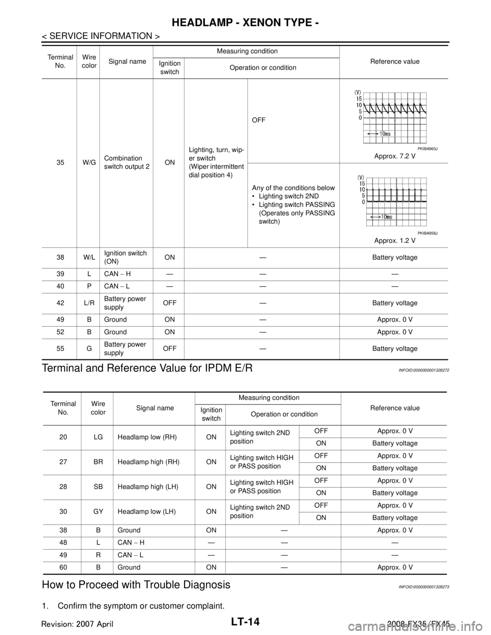
Terminal and Reference Value for IPDM E/R
INFOID:0000000001328272
How to Proceed with Trouble DiagnosisINFOID:0000000001328273
1. Confirm the symptom or customer complaint.
35 W/G Combination
switch output 2 ONLighting, turn, wip-
er switch
(Wiper intermittent
dial position 4) OFF
Approx. 7.2 V
Any of the conditions below
Lighting switch 2ND
Lighting switch PASSING (Operates only PASSING
switch)
Approx. 1.2 V
38 W/L Ignition switch
(ON)
ON — Battery voltage
39 L CAN − H— — —
40 P CAN − L— — —
42 L/R Battery power
supply
OFF — Battery voltage
49 B Ground ON — Approx. 0 V
52 B Ground ON — Approx. 0 V
55 G Battery power
supply OFF — Battery voltage
Te r m i n a l
No. Wire
color Signal name Measuring condition
Reference value
Ignition
switch Operation or condition
PKIB4960J
PKIB4958J
Te r m i n a l
No. Wire
color Signal name Measuring condition
Reference value
Ignition
switch Operation or condition
20 LG Headlamp low (RH) ON Lighting switch 2ND
positionOFF Approx. 0 V
ON Battery voltage
27 BR Headlamp high (RH) ON Lighting switch HIGH
or PASS positionOFF Approx. 0 V
ON Battery voltage
28 SB Headlamp high (LH) ON Lighting switch HIGH
or PASS positionOFF Approx. 0 V
ON Battery voltage
30 GY Headlamp low (LH) ON Lighting switch 2ND
positionOFF Approx. 0 V
ON Battery voltage
38 B Ground ON — Approx. 0 V
48 L CAN − H— — —
49 R CAN − L— — —
60 B Ground ON — Approx. 0 V
3AA93ABC3ACD3AC03ACA3AC03AC63AC53A913A773A893A873A873A8E3A773A983AC73AC93AC03AC3
3A893A873A873A8F3A773A9D3AAF3A8A3A8C3A863A9D3AAF3A8B3A8C
Page 3117 of 3924
HEADLAMP - XENON TYPE -LT-15
< SERVICE INFORMATION >
C
DE
F
G H
I
J
L
M A
B
LT
N
O P
2. Understand operation description and function description. Refer to LT- 5 , "System Description".
3. Perform Preliminary Check. Refer to LT-15, "
Preliminary Check".
4. Check symptom and repair or replace the cause of malfunction.
5. Does headlamp operate normally? If YES, GO TO 6. If NO, GO TO 4.
6. INSPECTION END
Preliminary CheckINFOID:0000000001328274
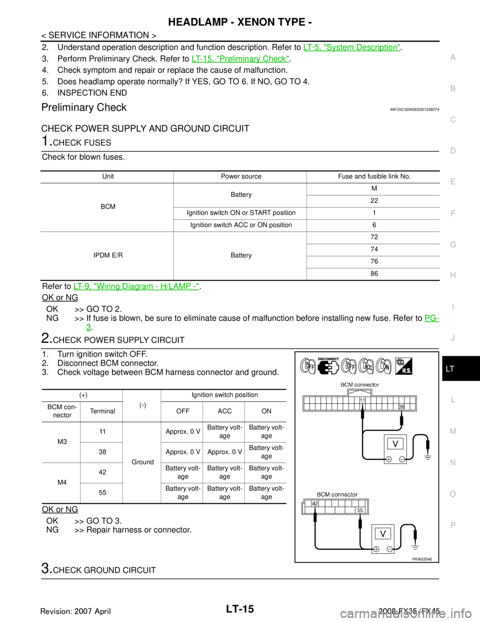
CHECK POWER SUPPLY AND GROUND CIRCUIT
1.CHECK FUSES
Check for blown fuses.
Refer to LT- 9 , "
Wiring Diagram - H/LAMP -".
OK or NG
OK >> GO TO 2.
NG >> If fuse is blown, be sure to eliminate caus e of malfunction before installing new fuse. Refer to PG-
3.
2.CHECK POWER SUPPLY CIRCUIT
1. Turn ignition switch OFF.
2. Disconnect BCM connector.
3. Check voltage between BCM harness connector and ground.
OK or NG
OK >> GO TO 3.
NG >> Repair harness or connector.
3.CHECK GROUND CIRCUIT
Unit Power source Fuse and fusible link No.
BCM Battery
M
22
Ignition switch ON or START position 1 Ignition switch ACC or ON position 6
IPDM E/R Battery 72
74
76
86
(+)
(-)Ignition switch position
BCM con- nector Terminal OFF ACC ON
M3 11
Ground Approx. 0 V
Battery volt-
age Battery volt-
age
38 Approx. 0 V Approx. 0 V Battery volt-
age
M4 42
Battery volt-
age Battery volt-
age Battery volt-
age
55 Battery volt-
age Battery volt-
age Battery volt-
age
PKIA5204E
3AA93ABC3ACD3AC03ACA3AC03AC63AC53A913A773A893A873A873A8E3A773A983AC73AC93AC03AC3
3A893A873A873A8F3A773A9D3AAF3A8A3A8C3A863A9D3AAF3A8B3A8C
Page 3143 of 3924
DAYTIME LIGHT SYSTEMLT-41
< SERVICE INFORMATION >
C
DE
F
G H
I
J
L
M A
B
LT
N
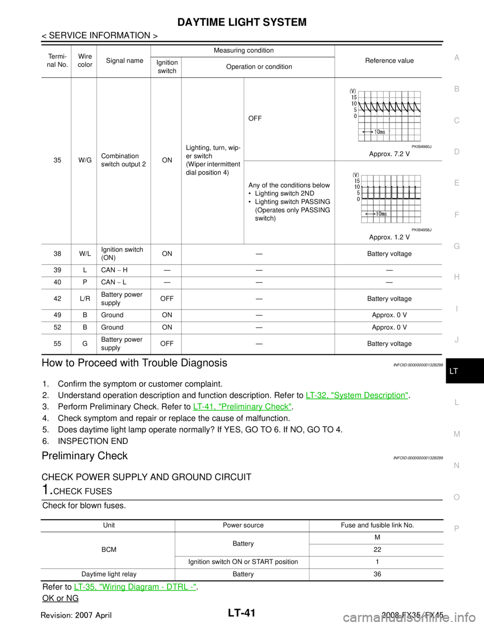
O PHow to Proceed with Trouble DiagnosisINFOID:0000000001328298
1. Confirm the symptom or customer complaint.
2. Understand operation description and function description. Refer to LT-32, "
System Description".
3. Perform Preliminary Check. Refer to LT-41, "
Preliminary Check".
4. Check symptom and repair or replace the cause of malfunction.
5. Does daytime light lamp operate normally? If YES, GO TO 6. If NO, GO TO 4.
6. INSPECTION END
Preliminary CheckINFOID:0000000001328299
CHECK POWER SUPPLY AND GROUND CIRCUIT
1.CHECK FUSES
Check for blown fuses.
Refer to LT-35, "
Wiring Diagram - DTRL -".
OK or NG
35 W/G Combination
switch output 2 ONLighting, turn, wip-
er switch
(Wiper intermittent
dial position 4) OFF
Approx. 7.2 V
Any of the conditions below
Lighting switch 2ND
Lighting switch PASSING (Operates only PASSING
switch)
Approx. 1.2 V
38 W/L Ignition switch
(ON)
ON — Battery voltage
39 L CAN − H— — —
40 P CAN − L— — —
42 L/R Battery power
supply
OFF — Battery voltage
49 B Ground ON — Approx. 0 V
52 B Ground ON — Approx. 0 V
55 G Battery power
supply OFF — Battery voltage
Te r m i -
nal No. Wire
color Signal name Measuring condition
Reference value
Ignition
switch Operation or condition
PKIB4960J
PKIB4958J
Unit Power source Fuse and fusible link No.
BCM Battery M
22
Ignition switch ON or START position 1
Daytime light relay Battery 36
3AA93ABC3ACD3AC03ACA3AC03AC63AC53A913A773A893A873A873A8E3A773A983AC73AC93AC03AC3
3A893A873A873A8F3A773A9D3AAF3A8A3A8C3A863A9D3AAF3A8B3A8C
Page 3144 of 3924
LT-42
< SERVICE INFORMATION >
DAYTIME LIGHT SYSTEM
OK >> GO TO 2.
NG >> If fuse is blown, be sure to eliminate cause of malfunction before installing new fuse. Refer to PG-
3.
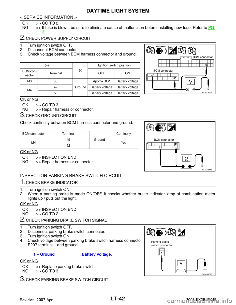
2.CHECK POWER SUPPLY CIRCUIT
1. Turn ignition switch OFF.
2. Disconnect BCM connector.
3. Check voltage between BCM harness connector and ground.
OK or NG
OK >> GO TO 3.
NG >> Repair harness or connector.
3.CHECK GROUND CIRCUIT
Check continuity between BCM harness connector and ground.
OK or NG
OK >> INSPECTION END
NG >> Repair harness or connector.
INSPECTION PARKING BRAKE SWITCH CIRCUIT
1.CHECK BRAKE INDICATOR
1. Turn ignition switch ON.
2. When a parking brake is made ON/OFF, it checks w hether brake indicator lamp of combination meter
lights up / puts out the light.
OK or NG
OK >> INSPECTION END
NG >> GO TO 2.
2.CHECK PARKING BRAKE SWITCH SIGNAL
1. Turn ignition switch OFF.
2. Disconnect parking brake switch connector.
3. Turn ignition switch ON.
4. Check voltage between parking brake switch harness connector E207 terminal 1 and ground.
OK or NG
OK >> Replace parking brake switch.
NG >> GO TO 3.
3.CHECK PARKING BRAKE SWITCH CIRCUIT
(+) (-)Ignition switch position
BCM con- nector Te r m i n a l O F F O N
M3 38 GroundApprox. 0 V Battery voltage
M4 42 Battery voltage Battery voltage
55 Battery voltage Battery voltage
PKIA7520E
BCM connector Terminal
GroundContinuity
M4 49
Ye s
52
SKIA5294E
1 – Ground : Battery voltage.
SKIA5876E
3AA93ABC3ACD3AC03ACA3AC03AC63AC53A913A773A893A873A873A8E3A773A983AC73AC93AC03AC3
3A893A873A873A8F3A773A9D3AAF3A8A3A8C3A863A9D3AAF3A8B3A8C
Page 3146 of 3924
LT-44
< SERVICE INFORMATION >
DAYTIME LIGHT SYSTEM
NOTE:
1. Vehicles without auto light system display this item, but cannot be monitored.
2. Vehicles without daytime light system display this item, but cannot be monitored.
3. This item is displayed, but cannot be monitored.
ACTIVE TEST
Display Item List
NOTE:
1. Vehicles without daytime light lamp system display this item, but cannot be tested.
2. This item is displayed, but cannot be tested.
Daytime Light Control Does Not Operate ProperlyINFOID:0000000001328301
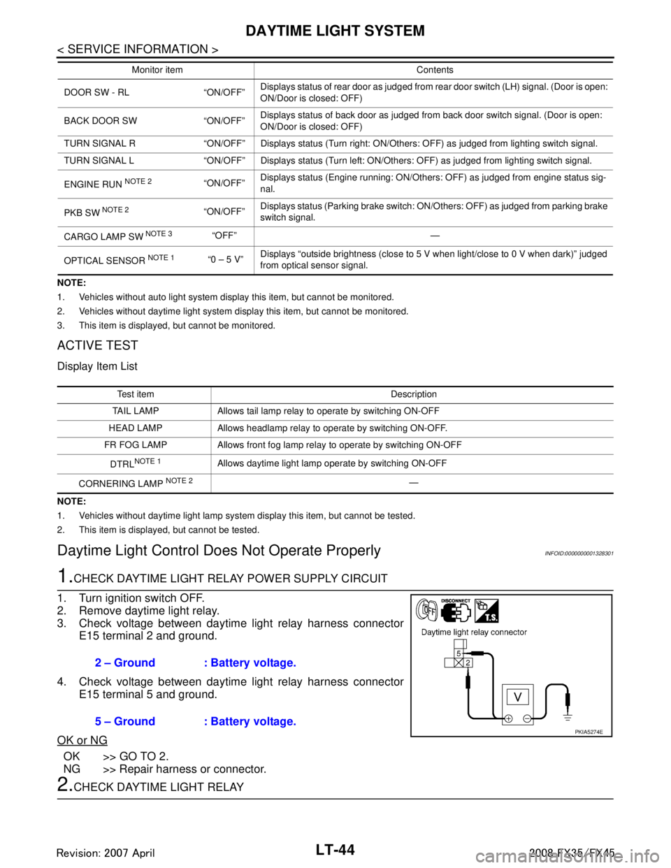
1.CHECK DAYTIME LIGHT RELAY POWER SUPPLY CIRCUIT
1. Turn ignition switch OFF.
2. Remove daytime light relay.
3. Check voltage between daytime light relay harness connector E15 terminal 2 and ground.
4. Check voltage between daytime light relay harness connector E15 terminal 5 and ground.
OK or NG
OK >> GO TO 2.
NG >> Repair harness or connector.
2.CHECK DAYTIME LIGHT RELAY
DOOR SW - RL “ON/OFF” Displays status of rear door as judged from rear door switch (LH) signal. (Door is open:
ON/Door is closed: OFF)
BACK DOOR SW “ON/OFF” Displays status of back door as judged from back door switch signal. (Door is open:
ON/Door is closed: OFF)
TURN SIGNAL R “ON/OFF” Displays status (Turn right: ON/Others: OFF) as judged from lighting switch signal.
TURN SIGNAL L “ON/OFF” Displays status (Turn left: ON/Others: OFF) as judged from lighting switch signal.
ENGINE RUN
NOTE 2“ON/OFF” Displays status (Engine running: ON/Others: OFF) as judged from engine status sig-
nal.
PKB SW
NOTE 2“ON/OFF” Displays status (Parking brake switch: ON/Others: OFF) as judged from parking brake
switch signal.
CARGO LAMP SW
NOTE 3 “OFF” —
OPTICAL SENSOR
NOTE 1 “0 – 5 V” Displays “outside brightness (close to 5 V when light/close to 0 V when dark)” judged
from optical sensor signal.
Monitor item Contents
Test item Description
TAIL LAMP Allows tail lamp relay to operate by switching ON-OFF
HEAD LAMP Allows headlamp relay to operate by switching ON-OFF.
FR FOG LAMP Allows front fog lamp relay to operate by switching ON-OFF
DTRL
NOTE 1Allows daytime light lamp operate by switching ON-OFF
CORNERING LAMP
NOTE 2—
2 – Ground : Battery voltage.
5 – Ground : Battery voltage.
PKIA5274E
3AA93ABC3ACD3AC03ACA3AC03AC63AC53A913A773A893A873A873A8E3A773A983AC73AC93AC03AC3
3A893A873A873A8F3A773A9D3AAF3A8A3A8C3A863A9D3AAF3A8B3A8C