2008 INFINITI FX35 Disc brakes
[x] Cancel search: Disc brakesPage 985 of 3924

BR-1
BRAKES
C
DE
G H
I
J
K L
M
SECTION BR
A
B
BR
N
O P
CONTENTS
BRAKE SYSTEM
SERVICE INFORMATION .. ..........................2
PRECAUTIONS .............................................. .....2
Precaution for Supplemental Restraint System
(SRS) "AIR BAG" and "SEAT BELT PRE-TEN-
SIONER" ............................................................. ......
2
Precaution for Procedure without Cowl Top Cover ......2
Precaution for Brake System ....................................2
PREPARATION ...................................................3
Commercial Service Tool .................................... ......3
NOISE, VIBRATION AND HARSHNESS
(NVH) TROUBLESHOOTING .............................
4
NVH Troubleshooting Chart ................................ ......4
BRAKE PEDAL .............................................. .....5
Inspection and Adjustment .................................. ......5
Component ................................................................6
Removal and Installation ...........................................6
BRAKE FLUID .....................................................8
On-Board Inspection ........................................... ......8
Drain and Refill ..........................................................8
Bleeding Brake System .............................................8
BRAKE TUBE AND HOSE ................................10
Hydraulic Circuit .................................................. ....10
Removal and Installation of Front Brake Tube and
Brake Hose .............................................................
10
Removal and Installation of Rear Brake Piping
and Brake Hose ......................................................
11
Inspection After Installation .....................................11
BRAKE MASTER CYLINDER ........................ ....12
On-Board Inspection ........................................... ....12
Component ..............................................................12
Removal and Installation .........................................12
Disassembly and Assembly ....................................13
BRAKE BOOSTER ...........................................14
On-Vehicle Service .............................................. ....14
Component ..............................................................14
Removal and Installation .........................................14
VACUUM LINES ...............................................16
Component ..............................................................16
Removal and Installation .........................................16
Inspection ................................................................16
FRONT DISC BRAKE .......................................18
On-Vehicle Inspection ......................................... ....18
Component ..............................................................18
Removal and Installation of Brake Pad ...................19
Removal and Installation of Brake Caliper Assem-
bly ........................................................................ ....
19
Disassembly and Assembly of Brake Caliper As-
sembly .....................................................................
20
Brake Burnishing Procedure ....................................23
REAR DISC BRAKE .........................................24
On-Vehicle Inspection ......................................... ....24
Component ..............................................................24
Removal and Installation of Brake Pad ...................25
Removal and Installation of Brake Caliper Assem-
bly ........................................................................ ....
25
Disassembly and Assembly of Brake Caliper As-
sembly .....................................................................
26
Brake Burnishing Procedure ....................................29
SERVICE DATA AND SPECIFICATIONS
(SDS) .................................................................
30
General Specification ..............................................30
Brake Pedal .............................................................30
Brake Booster ..........................................................30
Check Valve ............................................................30
Front Disc Brake ......................................................30
Rear Disc Brake ......................................................30
3AA93ABC3ACD3AC03ACA3AC03AC63AC53A913A773A893A873A873A8E3A773A983AC73AC93AC03AC3
3A893A873A873A8F3A773A9D3AAF3A8A3A8C3A863A9D3AAF3A8B3A8C
Page 1047 of 3924
![INFINITI FX35 2008 Service Manual
BRC-32
< SERVICE INFORMATION >[VDC/TCS/ABS]
TROUBLE DIAGNOSIS
Basic Inspection
INFOID:0000000001327676
BRAKE FLUID AMOUNT, LEAKS, AND BRAKE PADS INSPECTION
1. Check fluid level in the brake reservoir INFINITI FX35 2008 Service Manual
BRC-32
< SERVICE INFORMATION >[VDC/TCS/ABS]
TROUBLE DIAGNOSIS
Basic Inspection
INFOID:0000000001327676
BRAKE FLUID AMOUNT, LEAKS, AND BRAKE PADS INSPECTION
1. Check fluid level in the brake reservoir](/manual-img/42/57017/w960_57017-1046.png)
BRC-32
< SERVICE INFORMATION >[VDC/TCS/ABS]
TROUBLE DIAGNOSIS
Basic Inspection
INFOID:0000000001327676
BRAKE FLUID AMOUNT, LEAKS, AND BRAKE PADS INSPECTION
1. Check fluid level in the brake reservoir tank. If fluid level is low, refill brake fluid.
2. Check brake piping and around ABS actuator and electric uni t (control unit) for leaks. If there is leaking or
oozing fluid, check the following items.
If ABS actuator and electric unit (control unit) connec tion is loose, tighten piping to the specified torque
and re-perform the leak inspection to make sure there are no leaks.
If there is damage to the connection flare nut or AB S actuator and electric unit (control unit) screw,
replace the damaged part and re-perform the leak inspection to make sure there are no leaks.
When there is fluid leaking or oozing from a part other than ABS actuator and electric unit (control unit)
connection, if fluid is just oozing out, use a clean cl oth to wipe off the oozing fluid and re-check for leaks.
If fluid is still oozing out, replace the damaged part.
When there is fluid leaking or oozing at ABS actuator and electric unit (control unit), if fluid is just oozing
out, use a clean cloth to wipe off oozing fluid and re-che ck for leaks. If fluid is still oozing out, replace
ABS actuator and electric unit (control unit) body.
CAUTION:
ABS actuator and electric unit (contr ol unit) body can not be disassembled.
3. Check brake pad degree of wear. Refer to BR-18, "
On-Vehicle Inspection" in “Front Disc Brake” and BR-
24, "On-Vehicle Inspection" in “Rear Disc Brake”
POWER SYSTEM TERMINAL LOOSENESS AND BATTERY INSPECTION
Make sure battery positive cable, negative cabl e and ground connection are not loose. If looseness is
detected, tighten the cables. In additi on, check the battery voltage to make sure it has not dropped and alter-
nator is normal.
ABS WARNING LAMP, VDC OFF INDICATOR LAMP, SLIP INDICATOR LAMP AND BRAKE WARN-
ING LAMP INSPECTION
Symptom Symptom description Result
Motor operation noise This is noise of motor in
side ABS actuator and electr ic unit (control unit).
Slight noise may occur during VDC, TCS, and ABS operation.
Normal
When the vehicle speed goes over 20 km/h (12.5 MPH), motor and valves
operating noise may be heard. It happens only once after ignition switch is
ON. This is a normal status of the system operation check.
System operation check noise When engine starts, slight “click” noise may be heard from engine room.
This is normal and is part of system operation check. Normal
VDC/TCS operation
(SLIP indicator lamp blinking) TCS may activate momentarily if wheel speed changes when driving over
location where friction coefficient varies, when up/downshifting, or when ful-
ly depressing accelerator pedal.
Normal
Cancel the VDC/TCS
function for the inspec-
tion on a chassis dyna-
mometer.
For inspection of speedometer or other instruments, press VDC OFF switch
to turn VDC/TCS function off.
When accelerator pedal is depressed on a chassis dynamometer (fixed
front-wheel type), vehicle speed will not increase. This is not normal. It is re-
sult of TCS being activated by stationary front wheels. Warning lamp may
also illuminate to indicate “sensor system error”. This is also normal, and is
the result of the stationary front wheels being detected. To be certain, restart
engine, and drive vehicle at 30 km/h (19 MPH) or more. Make sure warning
lamp does not illuminate.
ABS operation
(Longer stopping distance) On roads with low friction coefficients, such as snowy roads or gravel roads,
vehicles with ABS may require a longer stopping distance. Therefore, when
driving on such roads, avoid overconfidence and keep speed sufficiently
low.
Normal
Insufficient feeling of accelera-
tion Depending on road conditions, driver may feel that feeling of acceleration is
insufficient. This is because traction control, which controls engine and
brakes to achieve optimal traction, has the highest priority (for safety). As a
result, there may be times when acceleration is slightly less than usual for
the same accelerator pedal operation.
Normal
3AA93ABC3ACD3AC03ACA3AC03AC63AC53A913A773A893A873A873A8E3A773A983AC73AC93AC03AC3
3A893A873A873A8F3A773A9D3AAF3A8A3A8C3A863A9D3AAF3A8B3A8C
Page 1064 of 3924
![INFINITI FX35 2008 Service Manual
TROUBLE DIAGNOSIS FOR SYMPTOMSBRC-49
< SERVICE INFORMATION > [VDC/TCS/ABS]
C
D
E
G H
I
J
K L
M A
B
BRC
N
O P
TROUBLE DIAGNOSIS FOR SYMPTOMS
Excessive ABS Function Operation FrequencyINFOID:000000000 INFINITI FX35 2008 Service Manual
TROUBLE DIAGNOSIS FOR SYMPTOMSBRC-49
< SERVICE INFORMATION > [VDC/TCS/ABS]
C
D
E
G H
I
J
K L
M A
B
BRC
N
O P
TROUBLE DIAGNOSIS FOR SYMPTOMS
Excessive ABS Function Operation FrequencyINFOID:000000000](/manual-img/42/57017/w960_57017-1063.png)
TROUBLE DIAGNOSIS FOR SYMPTOMSBRC-49
< SERVICE INFORMATION > [VDC/TCS/ABS]
C
D
E
G H
I
J
K L
M A
B
BRC
N
O P
TROUBLE DIAGNOSIS FOR SYMPTOMS
Excessive ABS Function Operation FrequencyINFOID:0000000001327692
1.CHECK FRONT AND REAR AXLE
Make sure there is no excessive looseness in the front and rear axles.
OK or NG
OK >> GO TO 2.
NG >> Check front or rear axle system.
2.CHECK WHEEL SENSOR
Perform following inspection for wheel sensor:
Sensor mount and damage inspection
Sensor rotor mount and damage inspection
Sensor connector connection inspection
Sensor harness inspection
OK or NG
OK >> GO TO 3.
NG >> Replace sensor or sensor rotor.
3.CHECK ABS WARNING LAMP DISPLAY
Make sure warning lamp turns off approximately 2 seconds after the ignition switch is turned ON or when driv-
ing.
OK or NG
OK >> Normal
NG >> Perform self-diagnosis. Refer to BRC-26, "
Self-Diagnosis".
Unexpected Pedal ReactionINFOID:0000000001327693
1.CHECK BRAKE PEDAL STROKE
Check brake pedal stroke.
Is the stroke too long?
YES >> Bleed air from brake piping. Check brake pedal, brake booster, and master cylinder mount for play, looseness, and brakesystem for fluid leaks, etc. If any malfunctions are found, make repair.
NO >> GO TO 2.
2.CHECK FUNCTION
Disconnect ABS actuator and electric unit (control unit) c onnector E56 and make sure that braking force is suf-
ficient when ABS in not operating. After the inspection, reconnect connector.
OK or NG
OK >> CHECK WHEEL SENSOR. Refer to BRC-49, "Excessive ABS Function Operation Frequency".
NG >> Check brake system.
The Braking Distance Is LongINFOID:0000000001327694
CAUTION:
On slippery road surfaces, the st opping distance might be longer wi th the ABS operating than when
the ABS is not operating.
1.CHECK FUNCTION
Disconnect ABS actuator and electric unit (control unit) connector E56 to deactivate ABS. In this condition,
check stopping distance. After inspection, connect connector.
OK or NG
OK >> Bleed air from brake piping. Check brake system.
NG >> CHECK WHEEL SENSOR. Refer to BRC-49, "
Excessive ABS Function Operation Frequency".
3AA93ABC3ACD3AC03ACA3AC03AC63AC53A913A773A893A873A873A8E3A773A983AC73AC93AC03AC3
3A893A873A873A8F3A773A9D3AAF3A8A3A8C3A863A9D3AAF3A8B3A8C
Page 3361 of 3924

PB-6
< SERVICE INFORMATION >
PARKING BRAKE SHOE
PARKING BRAKE SHOE
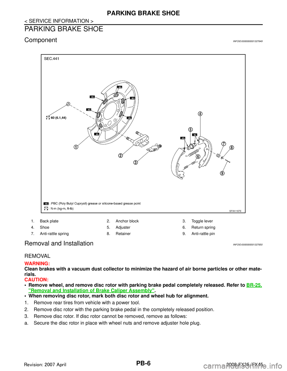
ComponentINFOID:0000000001327649
Removal and InstallationINFOID:0000000001327650
REMOVAL
WARNING:
Clean brakes with a vacuum dust collector to minimize the hazard of air borne particles or other mate-
rials.
CAUTION:
• Remove wheel, and remove disc rotor with parki ng brake pedal completely released. Refer to BR-25,
"Removal and Installation of Brake Caliper Assembly".
When removing disc rotor, mark both disc rotor and wheel hub for alignment.
1. Remove rear tires from vehicle with a power tool.
2. Remove disc rotor with the parking brake pedal in the completely released position.
3. Remove disc rotor. If disc rotor cannot be removed, remove as follows:
a. Secure the disc rotor in place with wheel nuts and remove adjuster hole plug.
1. Back plate 2. Anchor block 3. Toggle lever
4. Shoe 5. Adjuster 6. Return spring
7. Anti-rattle spring 8. Retainer 9. Anti-rattle pin
SFIA1167E
3AA93ABC3ACD3AC03ACA3AC03AC63AC53A913A773A893A873A873A8E3A773A983AC73AC93AC03AC3
3A893A873A873A8F3A773A9D3AAF3A8A3A8C3A863A9D3AAF3A8B3A8C
Page 3363 of 3924

PB-8
< SERVICE INFORMATION >
PARKING BRAKE SHOE
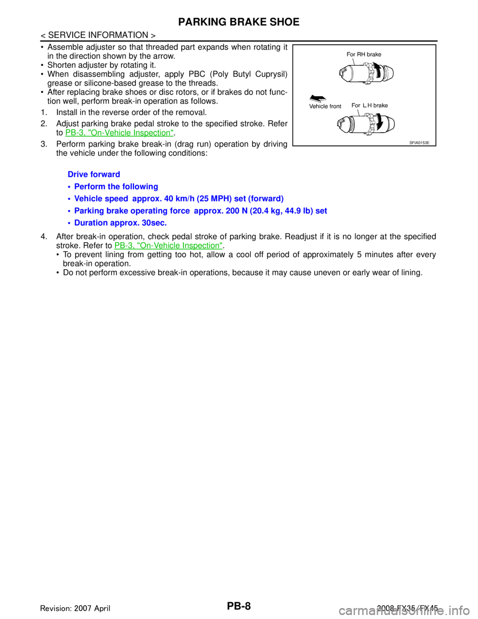
Assemble adjuster so that threaded part expands when rotating itin the direction shown by the arrow.
Shorten adjuster by rotating it.
When disassembling adjuster, apply PBC (Poly Butyl Cuprysil)
grease or silicone-based grease to the threads.
After replacing brake shoes or disc rotors, or if brakes do not func-
tion well, perform break-in operation as follows.
1. Install in the reverse order of the removal.
2. Adjust parking brake pedal stroke to the specified stroke. Refer to PB-3, "
On-Vehicle Inspection".
3. Perform parking brake break-in (drag run) operation by driving the vehicle under the following conditions:
4. After break-in operation, check pedal stroke of parking brake. Readjust if it is no longer at the specified
stroke. Refer to PB-3, "
On-Vehicle Inspection".
To prevent lining from getting too hot, allow a cool off period of approximately 5 minutes after every
break-in operation.
Do not perform excessive break-in operations, becaus e it may cause uneven or early wear of lining.
Drive forward
Perform the following
Vehicle speed approx. 40 km/h (25 MPH) set (forward)
Parking brake operating force approx. 200 N (20.4 kg, 44.9 lb) set
Duration approx. 30sec.
SFIA0153E
3AA93ABC3ACD3AC03ACA3AC03AC63AC53A913A773A893A873A873A8E3A773A983AC73AC93AC03AC3
3A893A873A873A8F3A773A9D3AAF3A8A3A8C3A863A9D3AAF3A8B3A8C