2008 INFINITI FX35 transfer
[x] Cancel search: transferPage 1133 of 3924

COMBINATION METERSDI-7
< SERVICE INFORMATION >
C
DE
F
G H
I
J
L
M A
B
DI
N
O P
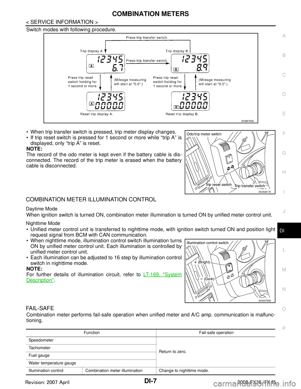
Switch modes with following procedure.
When trip transfer switch is pressed, trip meter display changes.
If trip reset switch is pressed for 1 second or more while “trip A” is displayed, only “trip A” is reset.
NOTE:
The record of the odo meter is kept even if the battery cable is dis-
connected. The record of the trip meter is erased when the battery
cable is disconnected.
COMBINATION METER ILLUMINATION CONTROL
Daytime Mode
When ignition switch is turned ON, combination meter il lumination is turned ON by unified meter control unit.
Nighttime Mode
Unified meter control unit is transferred to nighttime mode, with ignitio\
n switch turned ON and position light
request signal from BCM with CAN communication.
When nighttime mode, illumination c ontrol switch illumination turns
ON by unified meter control unit. Each illumination is controlled by
unified meter control unit.
Each illumination can be adjusted to 16 step by illumination control switch in nighttime mode.
NOTE:
For further details of illumination circuit, refer to LT-169, "
System
Description".
FA I L - S A F E
Combination meter performs fail-safe operation when unified meter and A/C amp. communication is malfunc-
tioning.
SKIB8760E
SKIA4817E
SKIA4795E
Function Fail-safe operation
Speedometer
Return to zero.
Tachometer
Fuel gauge
Water temperature gauge
Illumination control Combination meter illumination Change to nighttime mode.
3AA93ABC3ACD3AC03ACA3AC03AC63AC53A913A773A893A873A873A8E3A773A983AC73AC93AC03AC3
3A893A873A873A8F3A773A9D3AAF3A8A3A8C3A863A9D3AAF3A8B3A8C
Page 1139 of 3924

COMBINATION METERSDI-13
< SERVICE INFORMATION >
C
DE
F
G H
I
J
L
M A
B
DI
N
O P
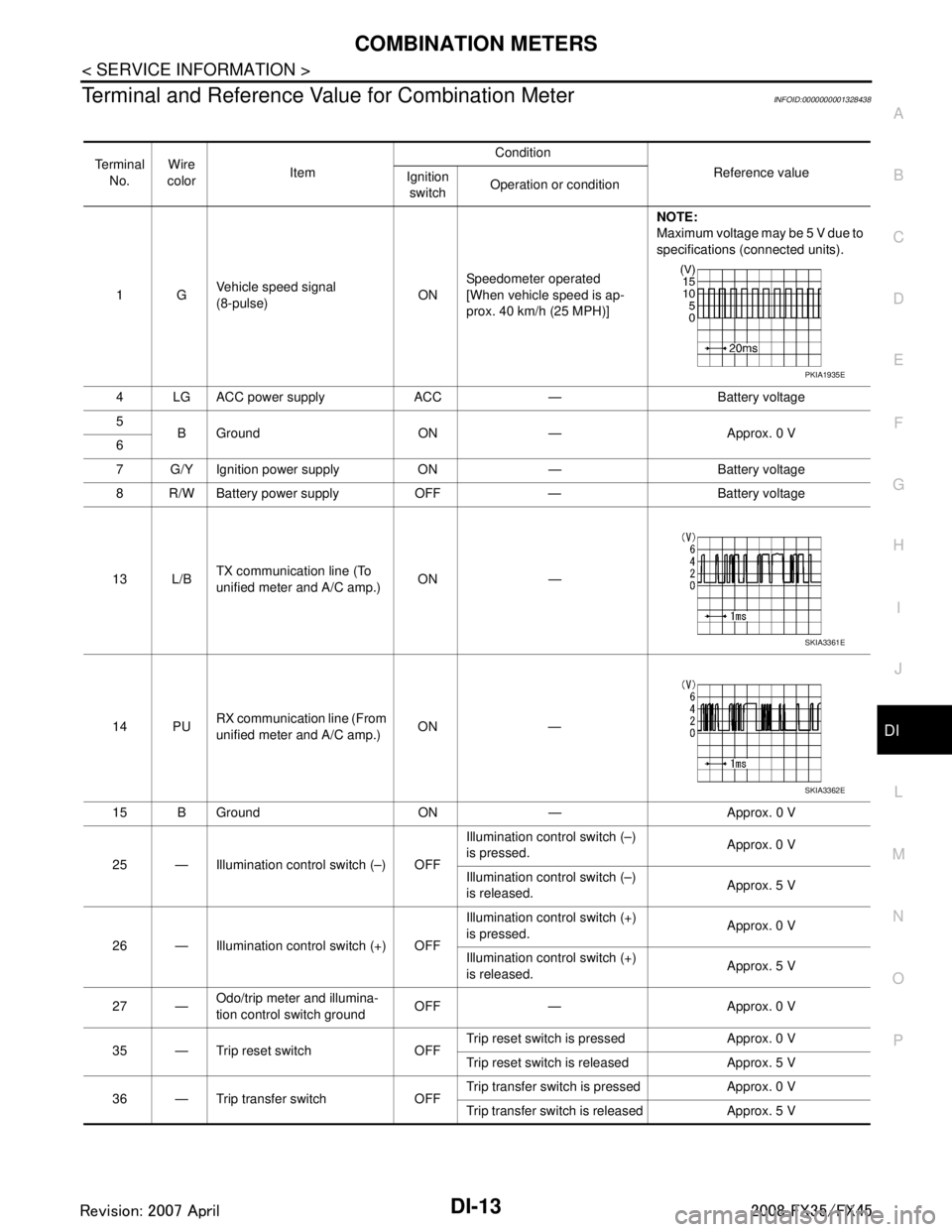
Terminal and Reference Va lue for Combination MeterINFOID:0000000001328438
Te r m i n a l
No. Wire
color Item Condition
Reference value
Ignition
switch Operation or condition
1G Vehicle speed signal
(8-pulse)
ONSpeedometer operated
[When vehicle speed is ap-
prox. 40 km/h (25 MPH)] NOTE:
Maximum voltage may be 5 V due to
specifications (connected units).
4 LG ACC power supply ACC — Battery voltage
5 B Ground ON — Approx. 0 V
6
7 G/Y Ignition power supply ON — Battery voltage
8 R/W Battery power supply OFF — Battery voltage
13 L/B TX communication line (To
unified meter and A/C amp.)
ON —
14 PU RX communication line (From
unified meter and A/C amp.) ON —
15 B Ground ON — Approx. 0 V
25 — Illumination control switch (–) OFF Illumination control switch (–)
is pressed.
Approx. 0 V
Illumination control switch (–)
is released. Approx. 5 V
26 — Illumination control switch (+) OFF Illumination control switch (+)
is pressed.
Approx. 0 V
Illumination control switch (+)
is released. Approx. 5 V
27 — Odo/trip meter and illumina-
tion control switch ground
OFF — Approx. 0 V
35 — Trip reset switch OFF Trip reset switch is pressed Approx. 0 V
Trip reset switch is released Approx. 5 V
36 — Trip transfer switch OFF Trip transfer switch is pressed Approx. 0 V
Trip transfer switch is released Approx. 5 V
PKIA1935E
SKIA3361E
SKIA3362E
3AA93ABC3ACD3AC03ACA3AC03AC63AC53A913A773A893A873A873A8E3A773A983AC73AC93AC03AC3
3A893A873A873A8F3A773A9D3AAF3A8A3A8C3A863A9D3AAF3A8B3A8C
Page 1141 of 3924

COMBINATION METERSDI-15
< SERVICE INFORMATION >
C
DE
F
G H
I
J
L
M A
B
DI
N
O P
3. Turn ignition switch ON while pressing trip transfer switch and trip reset switch at the same time.
4. After ignition switch is turned ON, release trip transfer switch and trip reset switch (within 7 seconds after the ignition switch is
turned ON).
5. All the segments on the odo/trip meter, A/T indi cator and ICC system display illuminates, and simulta-
neously the low-fuel warning lamp indicator illuminates. At this time, the unified meter control unit is turned
to self-diagnosis mode.
NOTE:
Check odo/trip meter switch and combination meter power supply and ground circuit when self-diagno-
sis mode of combination meter does not start. Replace combination meter if the results of the check are
normal.
If any of the segments are not disp layed, replace combination meter.
6. Each meter/gauge activates during pressing trip reset switch. (Then low-fuel warning lamp turns OFF.)
NOTE:
If any of the meters/gauges are not activated, replace thecombination meter.
The figure is reference.
CONSULT-III Function (METER/M&A)INFOID:0000000001328441
Refer to DI-27, "CONSULT-III Function (METER/M&A)" in “UNIFIED METER AND A/C AMP”.
Trouble DiagnosisINFOID:0000000001328442
HOW TO PERFORM TROUBLE DIAGNOSIS
1. Confirm the symptom or customer complaint.
2. Perform preliminary check. Refer to "PRELIMINARY CHECK".
3. According to the symptom chart, repair or replace the cause of the symptom. Refer to DI-16, "
Symptom
Chart".
4. Does the meter operate normally? If so, GO TO 5. If not, GO TO 2.
5. INSPECTION END
PRELIMINARY CHECK
1.CHECK OPERATION OF SELF-DIAGNOSIS MODE (COMBINATION METER)
SKIA4817E
SKIA6170E
SKIA4831E
3AA93ABC3ACD3AC03ACA3AC03AC63AC53A913A773A893A873A873A8E3A773A983AC73AC93AC03AC3
3A893A873A873A8F3A773A9D3AAF3A8A3A8C3A863A9D3AAF3A8B3A8C
Page 1148 of 3924

DI-22
< SERVICE INFORMATION >
COMBINATION METERS
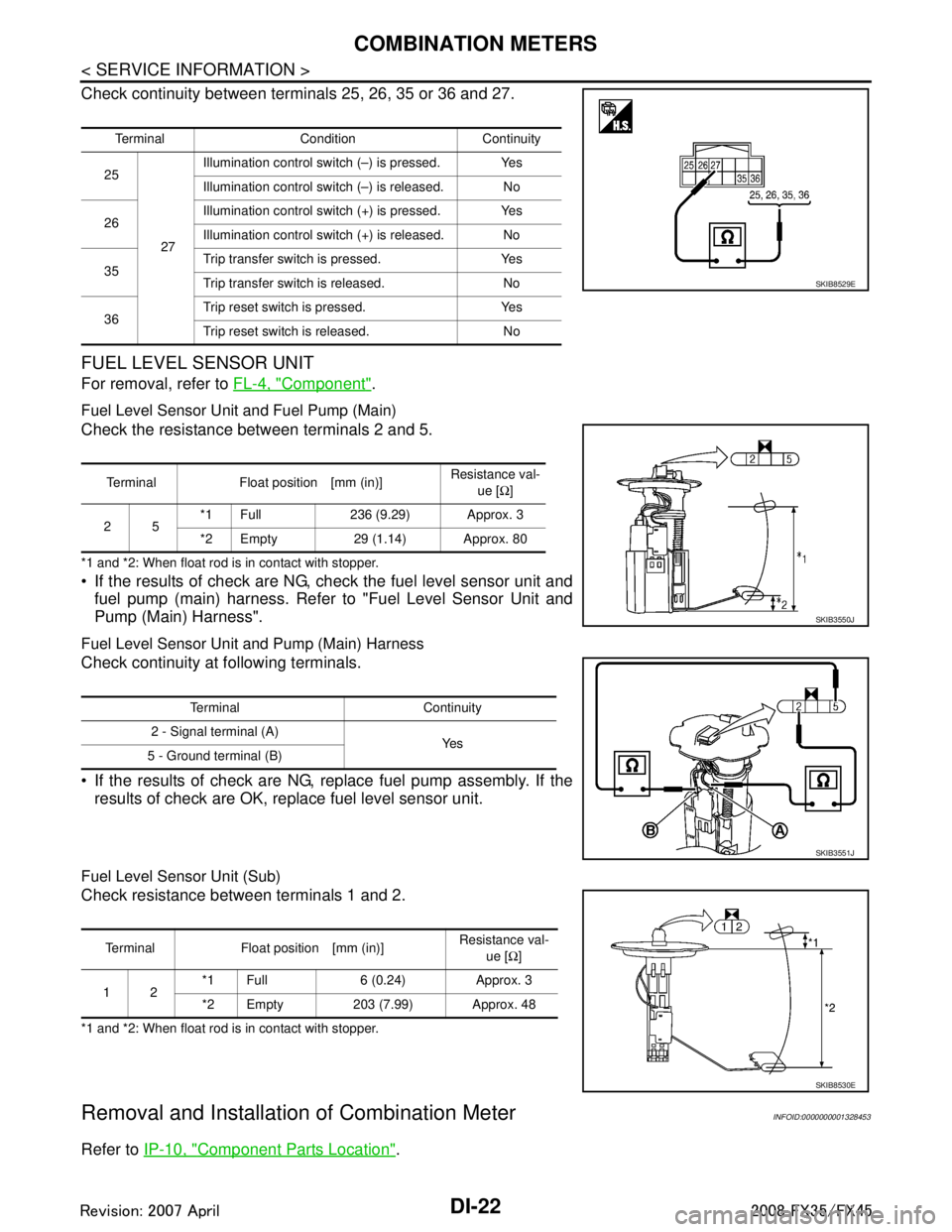
Check continuity between terminals 25, 26, 35 or 36 and 27.
FUEL LEVEL SENSOR UNIT
For removal, refer to FL-4, "Component".
Fuel Level Sensor Unit and Fuel Pump (Main)
Check the resistance between terminals 2 and 5.
*1 and *2: When float rod is in contact with stopper.
If the results of check are NG, check the fuel level sensor unit and
fuel pump (main) harness. Refer to "Fuel Level Sensor Unit and
Pump (Main) Harness".
Fuel Level Sensor Unit and Pump (Main) Harness
Check continuity at following terminals.
If the results of check are NG, replace fuel pump assembly. If the results of check are OK, replace fuel level sensor unit.
Fuel Level Sensor Unit (Sub)
Check resistance between terminals 1 and 2.
*1 and *2: When float rod is in contact with stopper.
Removal and Installation of Combination MeterINFOID:0000000001328453
Refer to IP-10, "Component Parts Location".
Terminal Condition Continuity
25
27Illumination control swit
ch (–) is pressed. Yes
Illumination control swit ch (–) is released. No
26 Illumination control swit
ch (+) is pressed. Yes
Illumination control swit ch (+) is released. No
35 Trip transfer switch is pressed. Yes
Trip transfer switch is released. No
36 Trip reset switch is pressed. Yes
Trip reset switch is released. No
SKIB8529E
Terminal Float position [mm (in)]
Resistance val-
ue [Ω]
25 *1 Full 236 (9.29) Approx. 3
*2 Empty 29 (1.14) Approx. 80
SKIB3550J
Terminal Continuity
2 - Signal terminal (A) Ye s
5 - Ground terminal (B)
SKIB3551J
Terminal Float position [mm (in)] Resistance val-
ue [Ω]
12 *1 Full 6 (0.24) Approx. 3
*2 Empty 203 (7.99) Approx. 48
SKIB8530E
3AA93ABC3ACD3AC03ACA3AC03AC63AC53A913A773A893A873A873A8E3A773A983AC73AC93AC03AC3
3A893A873A873A8F3A773A9D3AAF3A8A3A8C3A863A9D3AAF3A8B3A8C
Page 1675 of 3924
![INFINITI FX35 2008 Service Manual
DTC P1211 TCS CONTROL UNITEC-435
< SERVICE INFORMATION > [VQ35DE]
C
D
E
F
G H
I
J
K L
M A
EC
NP
O
DTC P1211 TCS CONTROL UNIT
DescriptionINFOID:0000000001326283
The malfunction information related to INFINITI FX35 2008 Service Manual
DTC P1211 TCS CONTROL UNITEC-435
< SERVICE INFORMATION > [VQ35DE]
C
D
E
F
G H
I
J
K L
M A
EC
NP
O
DTC P1211 TCS CONTROL UNIT
DescriptionINFOID:0000000001326283
The malfunction information related to](/manual-img/42/57017/w960_57017-1674.png)
DTC P1211 TCS CONTROL UNITEC-435
< SERVICE INFORMATION > [VQ35DE]
C
D
E
F
G H
I
J
K L
M A
EC
NP
O
DTC P1211 TCS CONTROL UNIT
DescriptionINFOID:0000000001326283
The malfunction information related to TCS is transferred through the CAN communication line from “ABS
actuator and electric unit (control unit)” to ECM.
Be sure to erase the malfunction
information such as DTC not only fo r “ABS actuator and electric unit
(control unit)” but also for ECM after TCS related repair.
On Board Diagnosis LogicINFOID:0000000001326284
Freeze frame data is not stored in the ECM for this self-diagnosis.
The MIL will not light up for this self-diagnosis.
DTC Confirmation ProcedureINFOID:0000000001326285
TESTING CONDITION:
Before performing the following procedure, confirm that battery voltage is more than 10.5V at idle.
1. Start engine and let it idle for at least 60 seconds.
2. Check 1st trip DTC.
3. If 1st trip DTC is detected, go to EC-435, "
Diagnosis Procedure".
Diagnosis ProcedureINFOID:0000000001326286
Go to BRC-34.
DTC No. Trouble diagnosis name DTC detecting condition Possible cause
P1211
1211 TCS control unit
ECM receives a malfunction information from
“ABS actuator and electric unit (Control unit)”. ABS actuator and electric unit (control
unit)
TCS related parts
3AA93ABC3ACD3AC03ACA3AC03AC63AC53A913A773A893A873A873A8E3A773A983AC73AC93AC03AC3
3A893A873A873A8F3A773A9D3AAF3A8A3A8C3A863A9D3AAF3A8B3A8C
Page 1790 of 3924
![INFINITI FX35 2008 Service Manual
EC-550
< SERVICE INFORMATION >[VQ35DE]
ELECTRICAL LOAD SIGNAL
ELECTRICAL LOAD SIGNAL
DescriptionINFOID:0000000001326435
The electrical load signal (Headlamp switch signal, et
c.) is transferred throu INFINITI FX35 2008 Service Manual
EC-550
< SERVICE INFORMATION >[VQ35DE]
ELECTRICAL LOAD SIGNAL
ELECTRICAL LOAD SIGNAL
DescriptionINFOID:0000000001326435
The electrical load signal (Headlamp switch signal, et
c.) is transferred throu](/manual-img/42/57017/w960_57017-1789.png)
EC-550
< SERVICE INFORMATION >[VQ35DE]
ELECTRICAL LOAD SIGNAL
ELECTRICAL LOAD SIGNAL
DescriptionINFOID:0000000001326435
The electrical load signal (Headlamp switch signal, et
c.) is transferred through the CAN communication line
from BCM to ECM via IPDM E/R.
CONSULT-III Reference Value in Data Monitor ModeINFOID:0000000001326436
Specification data are reference values.
Diagnosis ProcedureINFOID:0000000001326437
1.CHECK LOAD SIGNAL CIRCUIT OVERALL FUNCTION-I
1. Turn ignition switch ON.
2. Connect CONSULT-III and select “DATA MONITOR” mode.
3. Select “LOAD SIGNAL” and check indication under the following conditions.
OK or NG
OK >> GO TO 2.
NG >> GO TO 4.
2.CHECK LOAD SIGNAL CIRCUIT OVERALL FUNCTION-II
Check “LOAD SIGNAL” indication under the following conditions.
OK or NG
OK >> GO TO 3.
NG >> GO TO 5.
3.CHECK HEATER FAN SIGNAL CIRCUIT OVERALL FUNCTION
Check “HEATER FAN SW” in “DATA MONITOR” m ode with CONSULT-III under the following conditions.
OK or NG
OK >> INSPECTION END
NG >> GO TO 6.
4.CHECK REAR WINDOW DEFOGGER SYSTEM
MONITOR ITEM CONDITION SPECIFICATION
LOAD SIGNAL Ignition switch: ON Rear window defogger switch is ON
and/or lighting switch is in 2nd.
ON
Rear window defogger switch is OFF
and lighting switch is OFF. OFF
HEATER FAN SW Engine: After warming up, idle the
engine Heater fan: Operating. ON
Heater fan: Not operating OFF
Condition Indication
Rear window defogger switch: ON ON
Rear window defogger switch: OFF OFF
Condition Indication
Lighting switch: ON at 2nd position ON Lighting switch: OFF OFF
Condition Indication
Heater fan: Operating ON
Heater fan: Not operating OFF
3AA93ABC3ACD3AC03ACA3AC03AC63AC53A913A773A893A873A873A8E3A773A983AC73AC93AC03AC3
3A893A873A873A8F3A773A9D3AAF3A8A3A8C3A863A9D3AAF3A8B3A8C
Page 2387 of 3924
![INFINITI FX35 2008 Service Manual
ELECTRICAL LOAD SIGNALEC-1147
< SERVICE INFORMATION > [VK45DE]
C
D
E
F
G H
I
J
K L
M A
EC
NP
O
ELECTRICAL LOAD SIGNAL
DescriptionINFOID:0000000001327048
The electrical load signal (Headlamp switch si INFINITI FX35 2008 Service Manual
ELECTRICAL LOAD SIGNALEC-1147
< SERVICE INFORMATION > [VK45DE]
C
D
E
F
G H
I
J
K L
M A
EC
NP
O
ELECTRICAL LOAD SIGNAL
DescriptionINFOID:0000000001327048
The electrical load signal (Headlamp switch si](/manual-img/42/57017/w960_57017-2386.png)
ELECTRICAL LOAD SIGNALEC-1147
< SERVICE INFORMATION > [VK45DE]
C
D
E
F
G H
I
J
K L
M A
EC
NP
O
ELECTRICAL LOAD SIGNAL
DescriptionINFOID:0000000001327048
The electrical load signal (Headlamp switch signal, r
ear window defogger switch signal, etc.) is transferred
through the CAN communication line from BCM to ECM via IPDM E/R.
CONSULT-III Reference Val ue in Data Monitor ModeINFOID:0000000001327049
Specification data are reference values.
Diagnosis ProcedureINFOID:0000000001327050
1.CHECK LOAD SIGNAL CIRCUIT OVERALL FUNCTION-I
1. Turn ignition switch ON.
2. Connect CONSULT-III and select “DATA MONITOR” mode.
3. Select “LOAD SIGNAL” and check indication under the following conditions.
OK or NG
OK >> GO TO 2.
NG >> GO TO 4.
2.CHECK LOAD SIGNAL CIRCUIT OVERALL FUNCTION-II
Check “LOAD SIGNAL” indication under the following conditions.
OK or NG
OK >> GO TO 3.
NG >> GO TO 5.
3.CHECK HEATER FAN SIGNAL CIRCUIT OVERALL FUNCTION
Select “HEATER FAN SW” and check indication under the following conditions.
OK or NG
OK >> INSPECTION END
NG >> GO TO 6.
4.CHECK REAR WINDOW DEFOGGER SYSTEM
MONITOR ITEM CONDITION SPECIFICATION
LOAD SIGNAL Ignition switch: ON Rear window defogger switch: ON
and/or lighting switch: 2nd position
ON
Rear window defogger switch and lighting
switch: OFF OFF
HEATER FAN SW Engine: After warming up, idle the
engine Heater fan switch: ON ON
Heater fan switch: OFF OFF
Condition Indication
Rear window defogger switch: ON ON
Rear window defogger switch: OFF OFF
Condition Indication
Lighting switch: ON at 2nd position ON
Lighting switch: OFF OFF
Condition Indication
Heater fan control switch: ON ON
Heater fan control switch: OFF OFF
3AA93ABC3ACD3AC03ACA3AC03AC63AC53A913A773A893A873A873A8E3A773A983AC73AC93AC03AC3
3A893A873A873A8F3A773A9D3AAF3A8A3A8C3A863A9D3AAF3A8B3A8C
Page 2602 of 3924
![INFINITI FX35 2008 Service Manual
EM-118
< SERVICE INFORMATION >[VQ35DE]
ENGINE ASSEMBLY
At first, remove the engine, the transmission assembly
, the transfer assembly and the front final drive assem-
bly with front suspension member INFINITI FX35 2008 Service Manual
EM-118
< SERVICE INFORMATION >[VQ35DE]
ENGINE ASSEMBLY
At first, remove the engine, the transmission assembly
, the transfer assembly and the front final drive assem-
bly with front suspension member](/manual-img/42/57017/w960_57017-2601.png)
EM-118
< SERVICE INFORMATION >[VQ35DE]
ENGINE ASSEMBLY
At first, remove the engine, the transmission assembly
, the transfer assembly and the front final drive assem-
bly with front suspension member downward. Then separa te the engine, the transmission assembly, the trans-
fer and the front final drive assembly.
Preparation
1. Release fuel pressure. Refer to EC-87, "Fuel Pressure Check".
2. Drain engine coolant from radiator. Refer to CO-10, "
Changing Engine Coolant".
CAUTION:
Perform this step when engine is cold.
Do not spill engine coolant on drive belts.
3. Disconnect both battery terminals. Refer to SC-4, "
How to Handle Battery".
4. Remove the following parts: Engine cover: Refer to EM-19, "
Component".
Front road wheel and tires
Front and rear engine undercover
Front cross bar: Refer to FSU-16, "
Removal and Installation".
Cowl top cover (right): Refer to EI-23, "
Component Parts Location".
Air duct and air cleaner case assembly: EM-17, "
Component".
5. Discharge refrigerant from A/C circuit. Refer to ATC-120, "
HFC-134a (R-134a) Service Procedure".
6. Remove radiator hoses (upper and lower). Refer to CO-13, "
Component".
Engine Room
1. Disconnect heater hose from vehicle-side, and fit a plug onto hose end to prevent engine coolant leak.
2. Disconnect grounding cable (between vehicle to left bank cylinder head).
3. Disconnect battery positive cable harness at v ehicle side and temporarily fasten it on engine.
4. Disconnect A/C piping from A/C compressor, and tem porarily fasten it on vehicle with a rope. Refer to
ATC-120, "
HFC-134a (R-134a) Service Procedure".
5. Disconnect engine room harness connectors shown in the fig- ure.
6. Disconnect two body ground cables.
7. Disconnect brake booster vacuum hose.
8. Disconnect fuel feed hose (with damper) and EVAP hose. Refer to EM-45, "
Component"
CAUTION:
Fit plugs onto disconnected hoses to prevent fuel leak.
9. Remove reservoir tank of power steering oil pump and piping from vehicle, and temporarily secure them
on engine. Refer to PS-27, "
On-Vehicle Inspection and Service".
CAUTION:
When temporarily securing, keep the reservo ir tank upright to avoid a fluid leak.
Passenger Room Side
Follow procedure below to disconnect engine room har ness connectors at passenger room side, and tempo-
rarily secure them on engine.
1. Remove passenger-side kicking plate, das h side finisher, and glove box. Refer to EI-38, "
Component
Parts Location" and IP-10, "Component Parts Location".
SBIA0472E
3AA93ABC3ACD3AC03ACA3AC03AC63AC53A913A773A893A873A873A8E3A773A983AC73AC93AC03AC3
3A893A873A873A8F3A773A9D3AAF3A8A3A8C3A863A9D3AAF3A8B3A8C