2008 INFINITI FX35 transfer
[x] Cancel search: transferPage 3326 of 3924
RECOMMENDED FLUIDS AND LUBRICANTSMA-9
< SERVICE INFORMATION >
C
DE
F
G H
I
J
K
M A
B
MA
N
O P
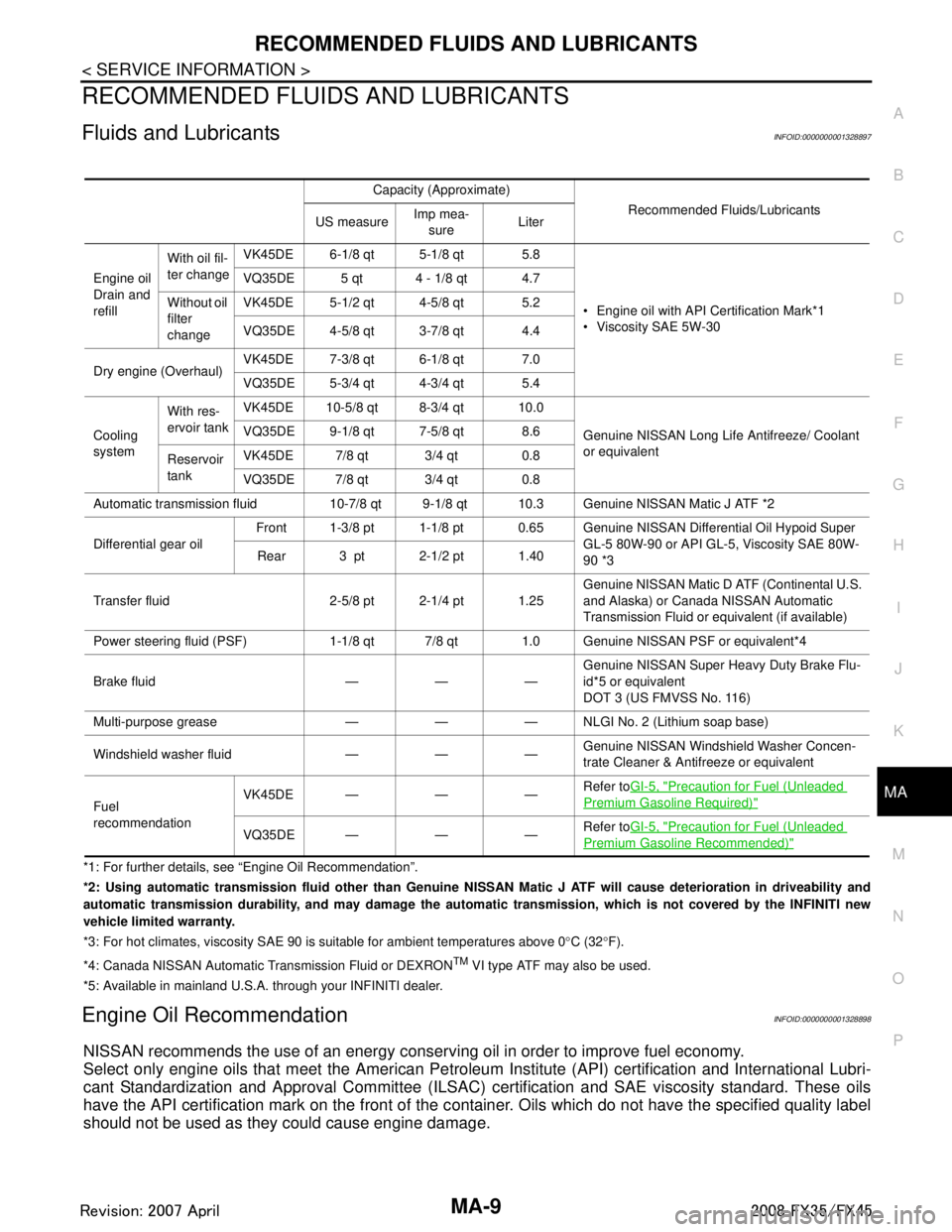
RECOMMENDED FLUIDS AND LUBRICANTS
Fluids and LubricantsINFOID:0000000001328897
*1: For further details, see “Engine Oil Recommendation”.
*2: Using automatic transmission fluid other than Genuine NISSAN Matic J ATF will cause deterioration in driveability and
automatic transmission durability, and may damage the automatic transmission, which is not covered by the INFINITI new
vehicle limited warranty.
*3: For hot climates, viscosity SAE 90 is suitable for ambient temperatures above 0 °C (32 °F).
*4: Canada NISSAN Au tomatic Transmission Fluid or DEXRON
TM VI type ATF may also be used.
*5: Available in mainland U.S.A. through your INFINITI dealer.
Engine Oil RecommendationINFOID:0000000001328898
NISSAN recommends the use of an energy conser ving oil in order to improve fuel economy.
Select only engine oils that meet the American Petroleum Institute (API) certification and International Lubri-
cant Standardization and Approval Committee (ILSAC) certification and SAE viscosity standard. These oils
have the API certification mark on the front of the c ontainer. Oils which do not have the specified quality label
should not be used as they could cause engine damage.
Capacity (Approximate)
Recommended Fluids/Lubricants
US measure Imp mea-
sure Liter
Engine oil
Drain and
refill With oil fil-
ter change
VK45DE 6-1/8 qt 5-1/8 qt 5.8
Engine oil with API Certification Mark*1
Viscosity SAE 5W-30
VQ35DE 5 qt 4 - 1/8 qt 4.7
Without oil
filter
change VK45DE 5-1/2 qt 4-5/8 qt 5.2
VQ35DE 4-5/8 qt 3-7/8 qt 4.4
Dry engine (Overhaul) VK45DE 7-3/8 qt 6-1/8 qt 7.0
VQ35DE 5-3/4 qt 4-3/4 qt 5.4
Cooling
system With res-
ervoir tank
VK45DE 10-5/8 qt 8-3/4 qt 10.0
Genuine NISSAN Long Life Antifreeze/ Coolant
or equivalent
VQ35DE 9-1/8 qt 7-5/8 qt 8.6
Reservoir
tank VK45DE 7/8 qt 3/4 qt 0.8
VQ35DE 7/8 qt 3/4 qt 0.8
Automatic transmission fluid 10-7/8 qt 9-1/8 qt 10.3 Genuine NISSAN Matic J ATF *2
Differential gear oil Front 1-3/8 pt 1-1/8 pt 0.65 Genuine NI
SSAN Differential Oil Hypoid Super
GL-5 80W-90 or API GL-5, Viscosity SAE 80W-
90 *3
Rear 3 pt 2-1/2 pt 1.40
Transfer fluid 2-5/8 pt 2-1/4 pt 1.25 Genuine NISSAN Matic D ATF (Continental U.S.
and Alaska) or Canada NISSAN Automatic
Transmission Fluid or equivalent (if available)
Power steering fluid (PSF) 1-1/8 qt 7/8 qt 1.0 Genuine NISSAN PSF or equivalent*4
Brake fluid — — — Genuine NISSAN Super He
avy Duty Brake Flu-
id*5 or equivalent
DOT 3 (US FMVSS No. 116)
Multi-purpose grease — — — NLGI No. 2 (Lithium soap base)
Windshield washer fluid — — — Genuine NISSAN Windshie
ld Washer Concen-
trate Cleaner & Antifreeze or equivalent
Fuel
recommendation VK45DE — — —
Refer to
GI-5, "
Precaution for Fuel (Unleaded
Premium Gasoline Required)"
VQ35DE——— Refer to
GI-5, "Precaution for Fuel (Unleaded
Premium Gasoline Recommended)"
3AA93ABC3ACD3AC03ACA3AC03AC63AC53A913A773A893A873A873A8E3A773A983AC73AC93AC03AC3
3A893A873A873A8F3A773A9D3AAF3A8A3A8C3A863A9D3AAF3A8B3A8C
Page 3345 of 3924
MA-28
< SERVICE INFORMATION >
CHASSIS AND BODY MAINTENANCE
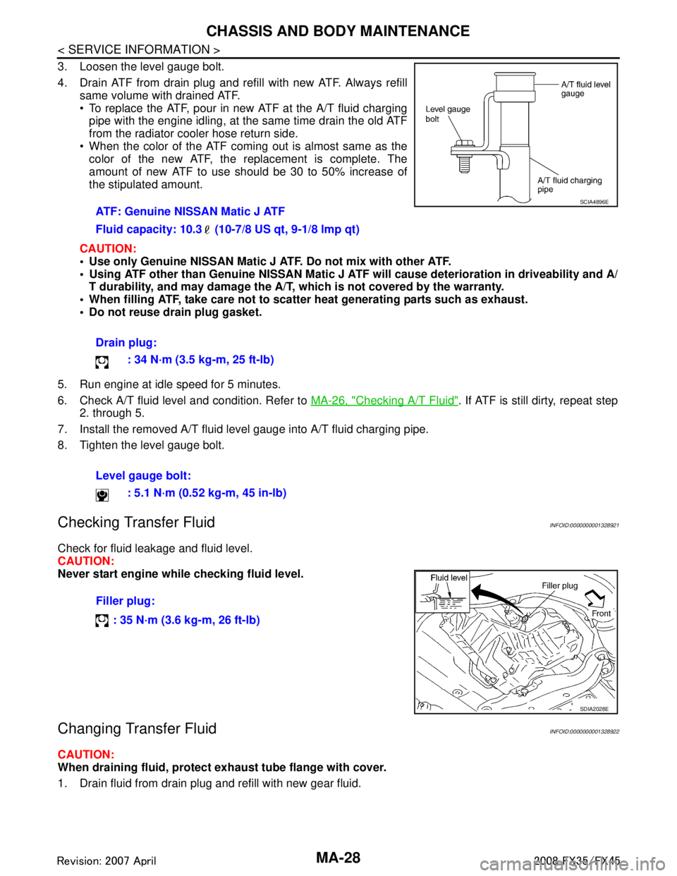
3. Loosen the level gauge bolt.
4. Drain ATF from drain plug and refill with new ATF. Always refillsame volume with drained ATF.
To replace the ATF, pour in new ATF at the A/T fluid charging
pipe with the engine idling, at the same time drain the old ATF
from the radiator cooler hose return side.
When the color of the ATF coming out is almost same as the color of the new ATF, the replacement is complete. The
amount of new ATF to use should be 30 to 50% increase of
the stipulated amount.
CAUTION:
Use only Genuine NISSAN Matic J ATF. Do not mix with other ATF.
Using ATF other than Genuine NISSAN Matic J AT F will cause deterioration in driveability and A/
T durability, and may damage the A/T, which is not covered by the warranty.
When filling ATF, take care not to scatter heat generating parts such as exhaust.
Do not reuse drain plug gasket.
5. Run engine at idle speed for 5 minutes.
6. Check A/T fluid level and condition. Refer to MA-26, "
Checking A/T Fluid". If ATF is still dirty, repeat step
2. through 5.
7. Install the removed A/T fluid level gauge into A/T fluid charging pipe.
8. Tighten the level gauge bolt.
Checking Transfer FluidINFOID:0000000001328921
Check for fluid leakage and fluid level.
CAUTION:
Never start engine while checking fluid level.
Changing Transfer FluidINFOID:0000000001328922
CAUTION:
When draining fluid, protect exh aust tube flange with cover.
1. Drain fluid from drain plug and refill with new gear fluid. ATF: Genuine NISSAN Matic J ATF
Fluid capacity: 10.3 (10-7/8 US qt, 9-1/8 lmp qt)
Drain plug:
: 34 N·m (3.5 kg-m, 25 ft-lb)
Level gauge bolt: : 5.1 N·m (0.52 kg-m, 45 in-lb)
SCIA4896E
Filler plug:
: 35 N·m (3.6 kg-m, 26 ft-lb)
SDIA2028E
3AA93ABC3ACD3AC03ACA3AC03AC63AC53A913A773A893A873A873A8E3A773A983AC73AC93AC03AC3
3A893A873A873A8F3A773A9D3AAF3A8A3A8C3A863A9D3AAF3A8B3A8C
Page 3439 of 3924
STANDARDIZED RELAYPG-75
< SERVICE INFORMATION >
C
DE
F
G H
I
J
L
M A
B
PG
N
O P
STANDARDIZED RELAY
DescriptionINFOID:0000000001328888
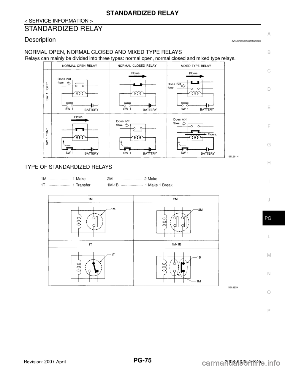
NORMAL OPEN, NORMAL CLOS ED AND MIXED TYPE RELAYS
Relays can mainly be divided into three types: normal open, normal closed and mixed type relays.
TYPE OF STANDARDIZED RELAYS
SEL881H
1M ···················· 1 Make 2M ···················· 2 Make
1T ···················· 1 Transfer 1M·1B ···················· 1 Make 1 Break
SEL882H
3AA93ABC3ACD3AC03ACA3AC03AC63AC53A913A773A893A873A873A8E3A773A983AC73AC93AC03AC3
3A893A873A873A8F3A773A9D3AAF3A8A3A8C3A863A9D3AAF3A8B3A8C
Page 3447 of 3924
FRONT PROPELLER SHAFTPR-5
< SERVICE INFORMATION >
CEF
G H
I
J
K L
M A
B
PR
N
O P
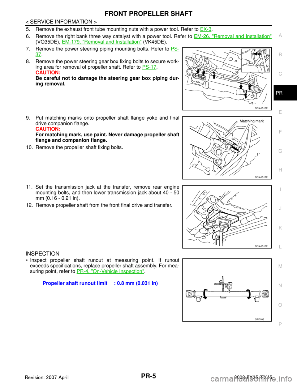
5. Remove the exhaust front tube mounting nuts with a power tool. Refer to EX-3.
6. Remove the right bank three way catalyst with a power tool. Refer to EM-26, "
Removal and Installation"
(VQ35DE), EM-179, "Removal and Installation" (VK45DE).
7. Remove the power steering piping mounting bolts. Refer to PS-
37.
8. Remove the power steering gear box fixing bolts to secure work- ing area for removal of propeller shaft. Refer to PS-17
.
CAUTION:
Be careful not to damage the steering gear box piping dur-
ing removal.
9. Put matching marks onto propeller shaft flange yoke and final drive companion flange.
CAUTION:
For matching mark, use paint. Never damage propeller shaft
flange and companion flange.
10. Remove the propeller shaft fixing bolts.
11. Set the transmission jack at the transfer, remove rear engine mounting bolts, and then lower transmission jack about 40 - 50
mm (0.16 - 0.21 in).
12. Remove propeller shaft from the front final drive and transfer.
INSPECTION
Inspect propeller shaft runout at measuring point. If runout exceeds specifications, replace propeller shaft assembly. For mea-
suring point, refer to PR-4, "
On-Vehicle Inspection".
SDIA1516E
SDIA1517E
SDIA1518E
Propeller shaft runout limit : 0.8 mm (0.031 in)
SPD106
3AA93ABC3ACD3AC03ACA3AC03AC63AC53A913A773A893A873A873A8E3A773A983AC73AC93AC03AC3
3A893A873A873A8F3A773A9D3AAF3A8A3A8C3A863A9D3AAF3A8B3A8C
Page 3448 of 3924
PR-6
< SERVICE INFORMATION >
FRONT PROPELLER SHAFT
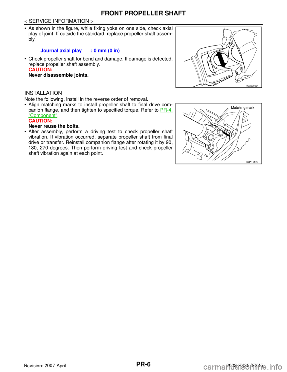
As shown in the figure, while fixing yoke on one side, check axialplay of joint. If outside the standard, replace propeller shaft assem-
bly.
Check propeller shaft for bend and damage. If damage is detected, replace propeller shaft assembly.
CAUTION:
Never disassemble joints.
INSTALLATION
Note the following, install in the reverse order of removal.
Align matching marks to install propeller shaft to final drive com-panion flange, and then tighten to specified torque. Refer to PR-4,
"Component".
CAUTION:
Never reuse the bolts.
After assembly, perform a driving test to check propeller shaft vibration. If vibration occurred, separate propeller shaft from final
drive or transfer. Reinstall companion flange after rotating it by 90,
180, 270 degrees. Then perform driving test and check propeller
shaft vibration again at each point. Journal axial play : 0 mm (0 in)
PDA0005D
SDIA1517E
3AA93ABC3ACD3AC03ACA3AC03AC63AC53A913A773A893A873A873A8E3A773A983AC73AC93AC03AC3
3A893A873A873A8F3A773A9D3AAF3A8A3A8C3A863A9D3AAF3A8B3A8C
Page 3452 of 3924
PR-10
< SERVICE INFORMATION >
REAR PROPELLER SHAFT
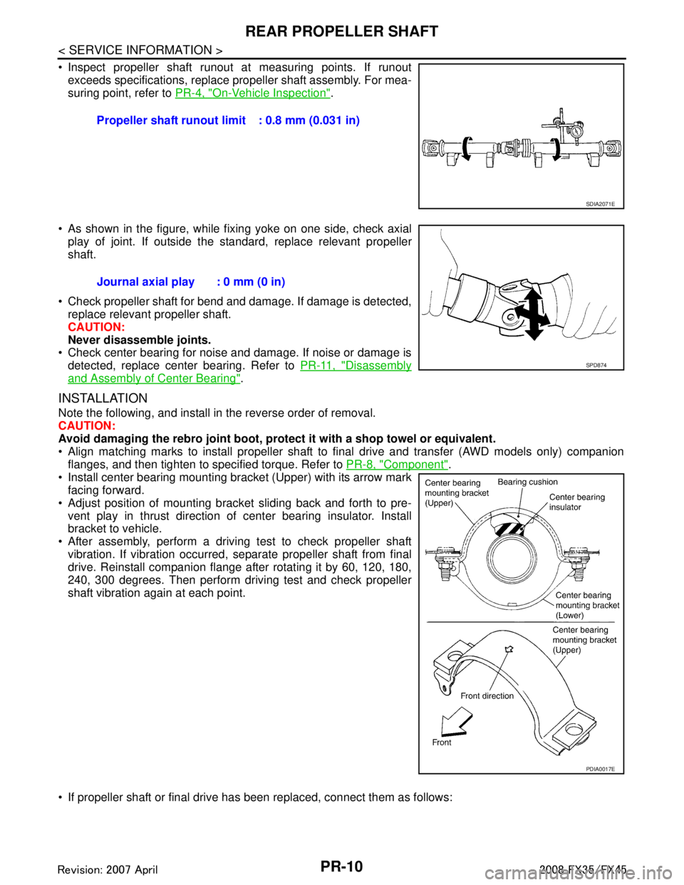
Inspect propeller shaft runout at measuring points. If runoutexceeds specifications, replace propeller shaft assembly. For mea-
suring point, refer to PR-4, "
On-Vehicle Inspection".
As shown in the figure, while fixing yoke on one side, check axial play of joint. If outside the standard, replace relevant propeller
shaft.
Check propeller shaft for bend and damage. If damage is detected, replace relevant propeller shaft.
CAUTION:
Never disassemble joints.
Check center bearing for noise and damage. If noise or damage is
detected, replace center bearing. Refer to PR-11, "
Disassembly
and Assembly of Center Bearing".
INSTALLATION
Note the following, and install in the reverse order of removal.
CAUTION:
Avoid damaging the rebro joint boot, protect it with a shop towel or equivalent.
Align matching marks to install propeller shaft to final drive and transfer (AWD models only) companion
flanges, and then tighten to specified torque. Refer to PR-8, "
Component".
Install center bearing mounting bracket (Upper) with its arrow mark
facing forward.
Adjust position of mounting bracket sliding back and forth to pre- vent play in thrust direction of center bearing insulator. Install
bracket to vehicle.
After assembly, perform a driving test to check propeller shaft vibration. If vibration occurred, separate propeller shaft from final
drive. Reinstall companion flange after rotating it by 60, 120, 180,
240, 300 degrees. Then perform driving test and check propeller
shaft vibration again at each point.
If propeller shaft or final drive has been replaced, connect them as follows: Propeller shaft runout limit : 0.8 mm (0.031 in)
SDIA2071E
Journal axial play : 0 mm (0 in)
SPD874
PDIA0017E
3AA93ABC3ACD3AC03ACA3AC03AC63AC53A913A773A893A873A873A8E3A773A983AC73AC93AC03AC3
3A893A873A873A8F3A773A9D3AAF3A8A3A8C3A863A9D3AAF3A8B3A8C
Page 3455 of 3924
SERVICE DATA AND SPECIFICATIONS (SDS)
PR-13
< SERVICE INFORMATION >
C EF
G H
I
J
K L
M A
B
PR
N
O P
SERVICE DATA AND SPECIFICATIONS (SDS)
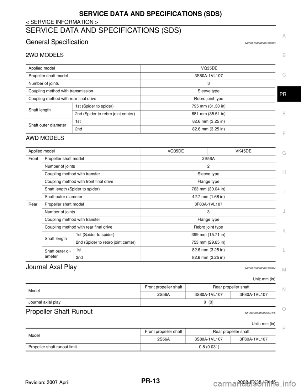
General SpecificationINFOID:0000000001327473
2WD MODELS
AWD MODELS
Journal Axal PlayINFOID:0000000001327474
Unit: mm (in)
Propeller Shaft RunoutINFOID:0000000001327475
Unit : mm (in)
Applied model VQ35DE
Propeller shaft model 3S80A-1VL107
Number of joints 3
Coupling method with transmission Sleeve type
Coupling method with rear final drive Rebro joint type
Shaft length 1st (Spider to spider) 795 mm (31.30 in)
2nd (Spider to rebro joint center) 681 mm (35.51 in)
Shaft outer diameter 1st 82.6 mm (3.25 in)
2nd 82.6 mm (3.25 in)
Applied model VQ35DE VK45DE
Front Propeller shaft model 2S56A
Number of joints 2
Coupling method with transfer Sleeve type
Coupling method with front final drive Flange type
Shaft length (Spider to spider) 763 mm (30.04 in)
Shaft outer diameter 42.7 mm (1.68 in)
Rear Propeller shaft model 3F80A-1VL107 Number of joints 3
Coupling method with transfer Flange type
Coupling method with rear final drive Rebro joint type
Shaft length 1st (Spider to spider) 399 mm (15.71 in)
2nd (Spider to rebro joint center) 753 mm (29.65 in)
Shaft outer di-
ameter 1st 82.6 mm (3.25 in)
2nd 82.6 mm (3.25 in)
Model
Front propeller shaft Rear propeller shaft
2S56A 3S80A-1VL107 3F80A-1VL107
Journal axial play 0 (0)
ModelFront propeller shaft Rear propeller shaft
2S56A 3S80A-1VL107 3F80A-1VL107
Propeller shaft runout limit 0.8 (0.031)
3AA93ABC3ACD3AC03ACA3AC03AC63AC53A913A773A893A873A873A8E3A773A983AC73AC93AC03AC3
3A893A873A873A8F3A773A9D3AAF3A8A3A8C3A863A9D3AAF3A8B3A8C
Page 3787 of 3924
TF-1
DRIVELINE/AXLE
CEF
G H
I
J
K L
M
SECTION TF
A
B
TF
N
O P
CONTENTS
TRANSFER
SERVICE INFORMATION .. ..........................3
DTC INDEX ..................................................... .....3
C1201-C1210, U1000 ......................................... ......3
PRECAUTIONS ...................................................4
Precaution for Supplemental Restraint System
(SRS) "AIR BAG" and "SEAT BELT PRE-TEN-
SIONER" ............................................................. ......
4
Precaution .................................................................4
Service Notice or Precaution .....................................5
PREPARATION ...................................................6
Special Service Tool ........................................... ......6
Commercial Service Tool ..........................................7
NOISE, VIBRATION AND HARSHNESS
(NVH) TROUBLESHOOTING .............................
9
NVH Troubleshooting Chart ................................ ......9
TRANSFER FLUID .............................................10
Replacement ....................................................... ....10
Inspection ................................................................10
AWD SYSTEM ................................................ ....11
Power Transfer Diagram ..................................... ....11
System Description .................................................11
Schematic ...............................................................13
CAN Communication ...............................................13
TROUBLE DIAGNOSIS .....................................14
Fail-Safe Function ............................................... ....14
How to Perform Trouble Diagnosis .........................14
Location of Electrical Parts ......................................15
Circuit Diagram .......................................................16
Wiring Diagram - AWD - ..........................................17
Trouble Diagnosis Chart by Symptom ....................20
AWD Control Unit Input/Output Signal Reference
Value ................................................................... ....
20
CONSULT-III Function (ALL MODE AWD/4WD) ....21
TROUBLE DIAGNOSIS FOR SYSTEM .............24
DTC C1201 CONTROLLER FAILURE ................ ....24
DTC C1203 ABS SYSTEM ......................................24
DTC C1204 4WD SOLENOID ............................. ....25
DTC C1205 4WD ACTUATOR RLY ........................27
DTC C1210 ENGINE SIGNAL 1 ..............................28
DTC U1000 CAN COMM CIRCUIT .........................28
Power Supply Circuit for AWD Control Unit .............28
TROUBLE DIAGNOSIS FOR SYMPTOMS ......30
AWD Warning Lamp Does Not Turn ON When the
Ignition Switch Is Turned to ON ...............................
30
AWD Warning Lamp Does Not Turn OFF Several
Seconds after Engine Started ..................................
30
Heavy Tight-Corner Braking Symptom Occurs
When the Vehicle Is Driven and the Steering
Wheel Is Turned Fully to Either Side after the En-
gine Is Started .........................................................
32
Vehicle Does Not Enter AWD Mode Even Though
AWD Warning Lamp Turned to OFF .......................
33
While Driving, AWD Warning Lamp Flashes Rap-
idly (When Flashing in Approx. 1 Minute and Then
Turning OFF) ....................................................... ....
33
While Driving, AWD Warning Lamp Flashes Slow-
ly (When Continuing to Flash until Turning Ignition
Switch OFF) .............................................................
33
AWD CONTROL UNIT ......................................35
Removal and Installation .........................................35
FRONT OIL SEAL .............................................36
Removal and Installation .........................................36
REAR OIL SEAL ...............................................37
Removal and Installation .........................................37
AIR BREATHER HOSE ....................................39
Removal and Installation .........................................39
TRANSFER ASSEMBLY ..................................40
Removal and Installation .........................................40
Disassembly and Assembly .....................................40
3AA93ABC3ACD3AC03ACA3AC03AC63AC53A913A773A893A873A873A8E3A773A983AC73AC93AC03AC3
3A893A873A873A8F3A773A9D3AAF3A8A3A8C3A863A9D3AAF3A8B3A8C