2008 INFINITI FX35 transfer
[x] Cancel search: transferPage 3791 of 3924
PRECAUTIONSTF-5
< SERVICE INFORMATION >
CEF
G H
I
J
K L
M A
B
TF
N
O P
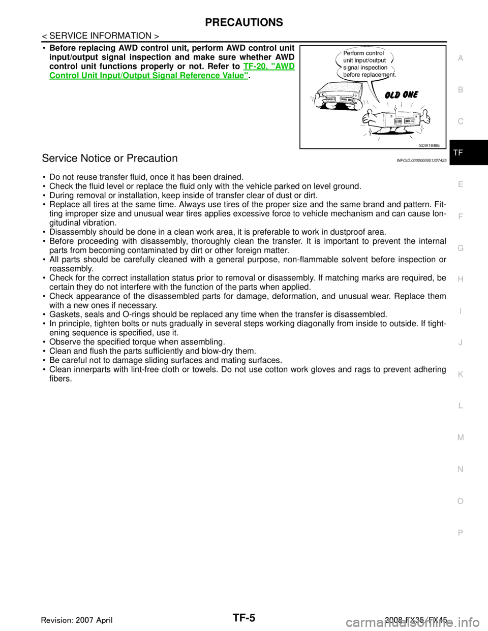
Before replacing AWD control unit, perform AWD control unit
input/output signal inspection and make sure whether AWD
control unit functions properly or not. Refer to TF-20, "
AW D
Control Unit Input/Output Signal Reference Value".
Service Notice or PrecautionINFOID:0000000001327425
Do not reuse transfer fluid, once it has been drained.
Check the fluid level or replace the fluid only with the vehicle parked on level ground.
During removal or installation, keep inside of transfer clear of dust or dirt.
Replace all tires at the same time. Always use tires of the proper size and the same brand and pattern. Fit-
ting improper size and unusual wear tires applies excessive force to vehicle mechanism and can cause lon-
gitudinal vibration.
Disassembly should be done in a clean work area, it is preferable to work in dustproof area.
Before proceeding with disassembly, thoroughly clean the tr ansfer. It is important to prevent the internal
parts from becoming contaminated by dirt or other foreign matter.
All parts should be carefully cleaned with a general purpose, non-flammable solvent before inspection or
reassembly.
Check for the correct installation status prior to remo val or disassembly. If matching marks are required, be
certain they do not interfere with t he function of the parts when applied.
Check appearance of the disassembled parts for dam age, deformation, and unusual wear. Replace them
with a new ones if necessary.
Gaskets, seals and O-rings should be replaced any time when the transfer is disassembled.
In principle, tighten bolts or nuts gradually in several steps working diagonally from inside to outside. If tight-
ening sequence is specified, use it.
Observe the specified torque when assembling.
Clean and flush the parts sufficiently and blow-dry them.
Be careful not to damage sliding surfaces and mating surfaces.
Clean innerparts with lint-free cloth or towels. Do not use cotton work gloves and rags to prevent adhering
fibers.
SDIA1848E
3AA93ABC3ACD3AC03ACA3AC03AC63AC53A913A773A893A873A873A8E3A773A983AC73AC93AC03AC3
3A893A873A873A8F3A773A9D3AAF3A8A3A8C3A863A9D3AAF3A8B3A8C
Page 3795 of 3924

NOISE, VIBRATION AND HARSHNESS (NVH) TROUBLESHOOTINGTF-9
< SERVICE INFORMATION >
CEF
G H
I
J
K L
M A
B
TF
N
O P
NOISE, VIBRATION AND HARSHN ESS (NVH) TROUBLESHOOTING
NVH Troubleshooting ChartINFOID:0000000001327428
Use the chart below to help you find the cause of the symptom. The numbers indicate the order of the inspec-
tion. If necessary, repair or replace these parts.
Reference pageTF-10TF-40TF-40TF-40TF-40TF-40
SUSPECTED PARTS
(Possible cause)
TRANSFER FLUID (Level low)
TRANSFER FLUID (Wrong)
TRANSFER FLUID (Level too high)
LIQUID GASKET (Damaged)
OIL SEAL (Worn or damaged)
GEAR (Worn or damaged)
BEARING (Worn or damaged)
TRANSFER CASE (Damaged)
Symptom Noise 1 2 3 3 3
Transfer fluid leakage 4 1 2 2 3
3AA93ABC3ACD3AC03ACA3AC03AC63AC53A913A773A893A873A873A8E3A773A983AC73AC93AC03AC3
3A893A873A873A8F3A773A9D3AAF3A8A3A8C3A863A9D3AAF3A8B3A8C
Page 3796 of 3924
TF-10
< SERVICE INFORMATION >
TRANSFER FLUID
TRANSFER FLUID
ReplacementINFOID:0000000001327429
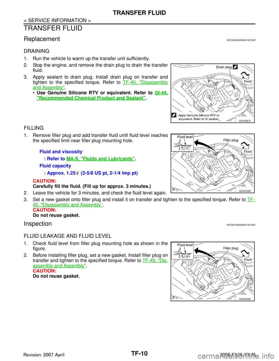
DRAINING
1. Run the vehicle to warm up the transfer unit sufficiently.
2. Stop the engine, and remove the drain plug to drain the transferfluid.
3. Apply sealant to drain plug. Install drain plug on transfer and tighten to the specified torque. Refer to TF-40, "
Disassembly
and Assembly".
Use Genuine Silicone RTV or equivalent. Refer to GI-44,
"Recommended Chemical Product and Sealant".
FILLING
1. Remove filler plug and add transfer fluid until fluid level reaches
the specified limit near filler plug mounting hole.
CAUTION:
Carefully fill the fluid. (Fil l up for approx. 3 minutes.)
2. Leave the vehicle for 3 minutes, and check the fluid level again.
3. Set a new gasket onto filler plug and install it on tr ansfer and tighten to the specified torque. Refer to TF-
40, "Disassembly and Assembly".
CAUTION:
Do not reuse gasket.
InspectionINFOID:0000000001327430
FLUID LEAKAGE AND FLUID LEVEL
1. Check fluid level from filler plug mounting hole as shown in the
figure.
2. Before installing filler plug, set a new gasket. Install filler plug on transfer and tighten to the specified torque. Refer to TF-40, "
Dis-
assembly and Assembly".
CAUTION:
Do not reuse gasket.
SDIA2087E
Fluid and viscosity
: Refer to MA-9, "
Fluids and Lubricants".
Fluid capacity
: Approx. 1.25 (2-5/8 US pt, 2-1/4 lmp pt)
SDIA2028E
SDIA2028E
3AA93ABC3ACD3AC03ACA3AC03AC63AC53A913A773A893A873A873A8E3A773A983AC73AC93AC03AC3
3A893A873A873A8F3A773A9D3AAF3A8A3A8C3A863A9D3AAF3A8B3A8C
Page 3797 of 3924
AWD SYSTEMTF-11
< SERVICE INFORMATION >
CEF
G H
I
J
K L
M A
B
TF
N
O P
AWD SYSTEM
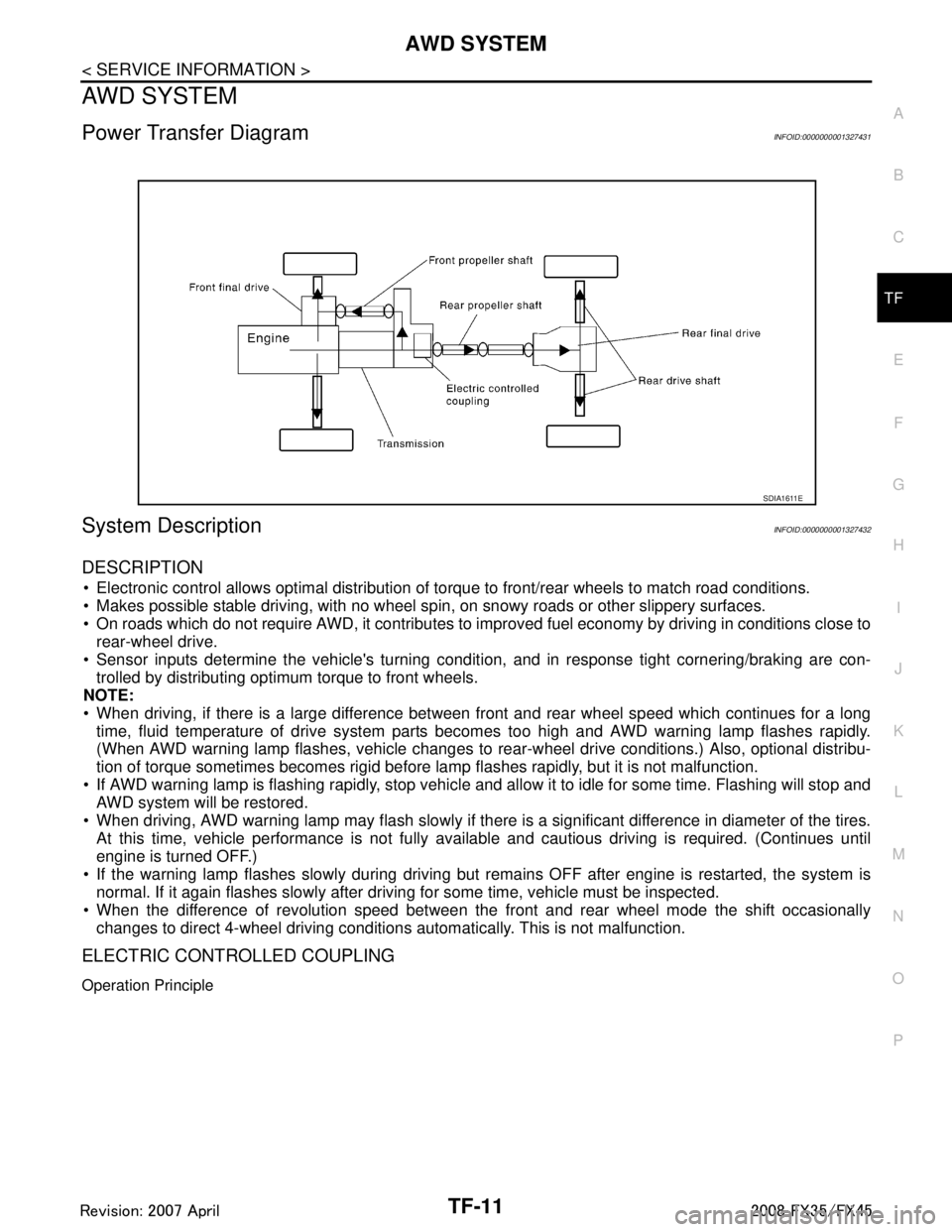
Power Transfer DiagramINFOID:0000000001327431
System DescriptionINFOID:0000000001327432
DESCRIPTION
Electronic control allows optimal distribution of torque to front/rear wheels to match road conditions.
Makes possible stable driving, with no wheel sp in, on snowy roads or other slippery surfaces.
On roads which do not require AWD, it contributes to improved fuel economy by driving in conditions close to
rear-wheel drive.
Sensor inputs determine the vehicle's turning conditi on, and in response tight cornering/braking are con-
trolled by distributing optimum torque to front wheels.
NOTE:
When driving, if there is a large difference between front and rear wheel speed which continues for a long
time, fluid temperature of drive system parts becom es too high and AWD warning lamp flashes rapidly.
(When AWD warning lamp flashes, vehicle changes to r ear-wheel drive conditions.) Also, optional distribu-
tion of torque sometimes becomes rigid before lamp flashes rapidly, but it is not malfunction.
If AWD warning lamp is flashing rapidly, stop vehicle and allow it to idle for some time. Flashing will stop and AWD system will be restored.
When driving, AWD warning lamp may flash slowly if ther e is a significant difference in diameter of the tires.
At this time, vehicle performance is not fully avail able and cautious driving is required. (Continues until
engine is turned OFF.)
If the warning lamp flashes slowly during driving but remains OFF after engine is restarted, the system is
normal. If it again flashes slowly after driving for some time, vehicle must be inspected.
When the difference of revolution speed between the front and rear wheel mode the shift occasionally
changes to direct 4-wheel driving conditions automatically. This is not malfunction.
ELECTRIC CONTROLLED COUPLING
Operation Principle
SDIA1611E
3AA93ABC3ACD3AC03ACA3AC03AC63AC53A913A773A893A873A873A8E3A773A983AC73AC93AC03AC3
3A893A873A873A8F3A773A9D3AAF3A8A3A8C3A863A9D3AAF3A8B3A8C
Page 3812 of 3924
TF-26
< SERVICE INFORMATION >
TROUBLE DIAGNOSIS FOR SYSTEM
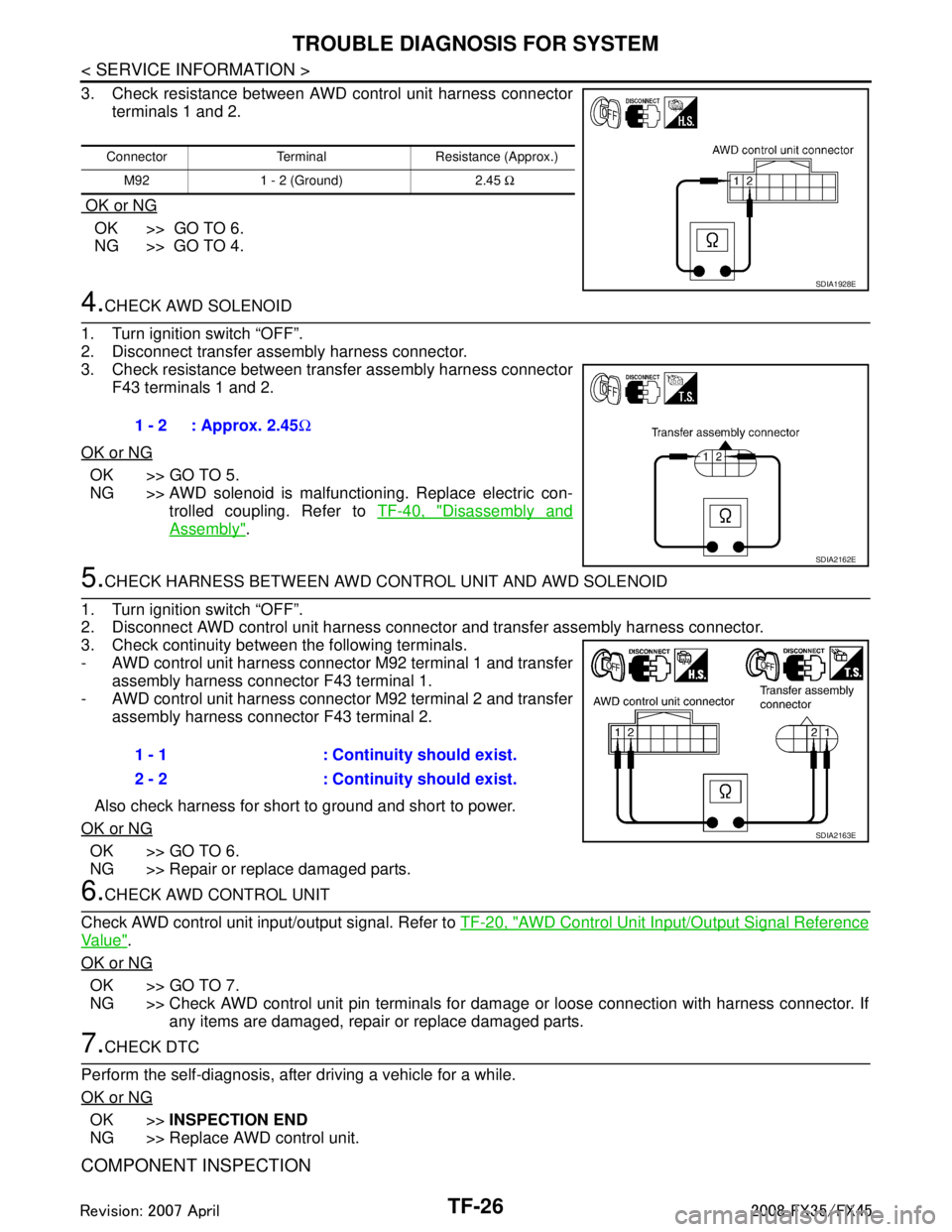
3. Check resistance between AWD control unit harness connectorterminals 1 and 2.
OK or NG
OK >> GO TO 6.
NG >> GO TO 4.
4.CHECK AWD SOLENOID
1. Turn ignition switch “OFF”.
2. Disconnect transfer assembly harness connector.
3. Check resistance between transfer assembly harness connector F43 terminals 1 and 2.
OK or NG
OK >> GO TO 5.
NG >> AWD solenoid is malfunctioning. Replace electric con- trolled coupling. Refer to TF-40, "
Disassembly and
Assembly".
5.CHECK HARNESS BETWEEN AWD CO NTROL UNIT AND AWD SOLENOID
1. Turn ignition switch “OFF”.
2. Disconnect AWD control unit harness connecto r and transfer assembly harness connector.
3. Check continuity between the following terminals.
- AWD control unit harness connector M92 terminal 1 and transfer assembly harness connector F43 terminal 1.
- AWD control unit harness connector M92 terminal 2 and transfer assembly harness connector F43 terminal 2.
Also check harness for short to ground and short to power.
OK or NG
OK >> GO TO 6.
NG >> Repair or replace damaged parts.
6.CHECK AWD CONTROL UNIT
Check AWD control unit input/output signal. Refer to TF-20, "
AWD Control Unit Input/Output Signal Reference
Va l u e".
OK or NG
OK >> GO TO 7.
NG >> Check AWD control unit pin terminals for dam age or loose connection with harness connector. If
any items are damaged, repair or replace damaged parts.
7.CHECK DTC
Perform the self-diagnosis, after driving a vehicle for a while.
OK or NG
OK >> INSPECTION END
NG >> Replace AWD control unit.
COMPONENT INSPECTION
Connector Terminal Resistance (Approx.)
M92 1 - 2 (Ground) 2.45 Ω
SDIA1928E
1 - 2 : Approx. 2.45Ω
SDIA2162E
1 - 1 : Continuity should exist.
2 - 2 : Continuity should exist.
SDIA2163E
3AA93ABC3ACD3AC03ACA3AC03AC63AC53A913A773A893A873A873A8E3A773A983AC73AC93AC03AC3
3A893A873A873A8F3A773A9D3AAF3A8A3A8C3A863A9D3AAF3A8B3A8C
Page 3813 of 3924
TROUBLE DIAGNOSIS FOR SYSTEMTF-27
< SERVICE INFORMATION >
CEF
G H
I
J
K L
M A
B
TF
N
O P
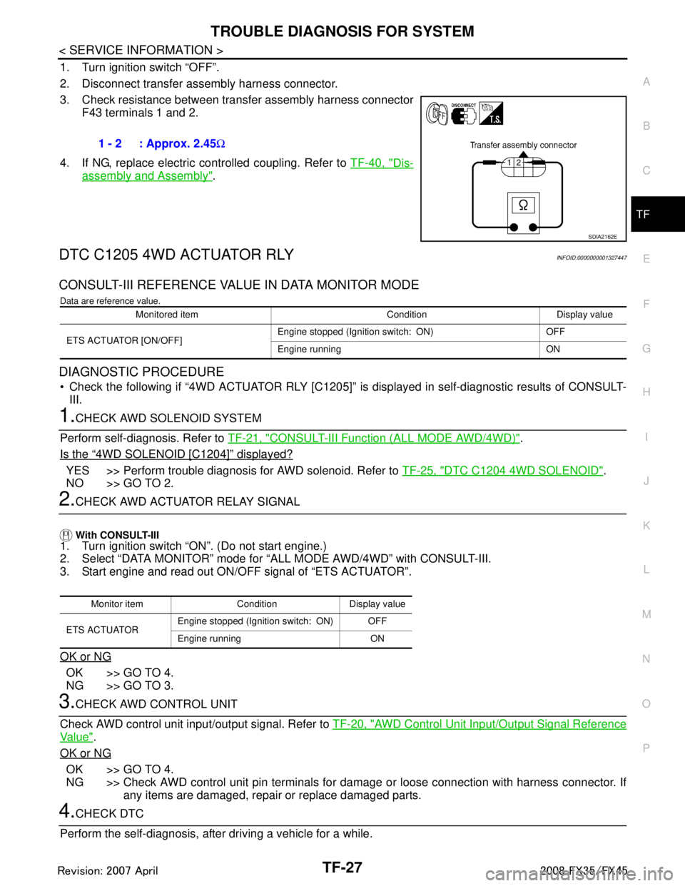
1. Turn ignition switch “OFF”.
2. Disconnect transfer assembly harness connector.
3. Check resistance between transfer assembly harness connector F43 terminals 1 and 2.
4. If NG, replace electric controlled coupling. Refer to TF-40, "
Dis-
assembly and Assembly".
DTC C1205 4WD ACTUATOR RLYINFOID:0000000001327447
CONSULT-III REFERENCE VALUE IN DATA MONITOR MODE
Data are reference value.
DIAGNOSTIC PROCEDURE
Check the following if “4WD ACTUATOR RLY [C1205]” is displayed in self-diagnostic results of CONSULT-
III.
1.CHECK AWD SOLENOID SYSTEM
Perform self-diagnosis. Refer to TF-21, "
CONSULT-III Function (ALL MODE AWD/4WD)".
Is the
“4WD SOLENOID [C1204]” displayed?
YES >> Perform trouble diagnosis for AWD solenoid. Refer to TF-25, "DTC C1204 4WD SOLENOID".
NO >> GO TO 2.
2.CHECK AWD ACTUATOR RELAY SIGNAL
With CONSULT-III
1. Turn ignition switch “ON”. (Do not start engine.)
2. Select “DATA MONITOR” mode for “A LL MODE AWD/4WD” with CONSULT-III.
3. Start engine and read out ON/OFF signal of “ETS ACTUATOR”.
OK or NG
OK >> GO TO 4.
NG >> GO TO 3.
3.CHECK AWD CONTROL UNIT
Check AWD control unit input/output signal. Refer to TF-20, "
AWD Control Unit Input/Output Signal Reference
Va l u e".
OK or NG
OK >> GO TO 4.
NG >> Check AWD control unit pin terminals for damage or loose connection with harness connector. If any items are damaged, repair or replace damaged parts.
4.CHECK DTC
Perform the self-diagnosis, after driving a vehicle for a while. 1 - 2 : Approx. 2.45
Ω
SDIA2162E
Monitored item Condition Display value
ETS ACTUATOR [ON/OFF] Engine stopped (Ignition switch: ON) OFF
Engine running ON
Monitor item Condition Display value
ETS ACTUATOR Engine stopped (Ignition switch: ON) OFF
Engine running ON
3AA93ABC3ACD3AC03ACA3AC03AC63AC53A913A773A893A873A873A8E3A773A983AC73AC93AC03AC3
3A893A873A873A8F3A773A9D3AAF3A8A3A8C3A863A9D3AAF3A8B3A8C
Page 3822 of 3924
TF-36
< SERVICE INFORMATION >
FRONT OIL SEAL
FRONT OIL SEAL
Removal and InstallationINFOID:0000000001327457
REMOVAL
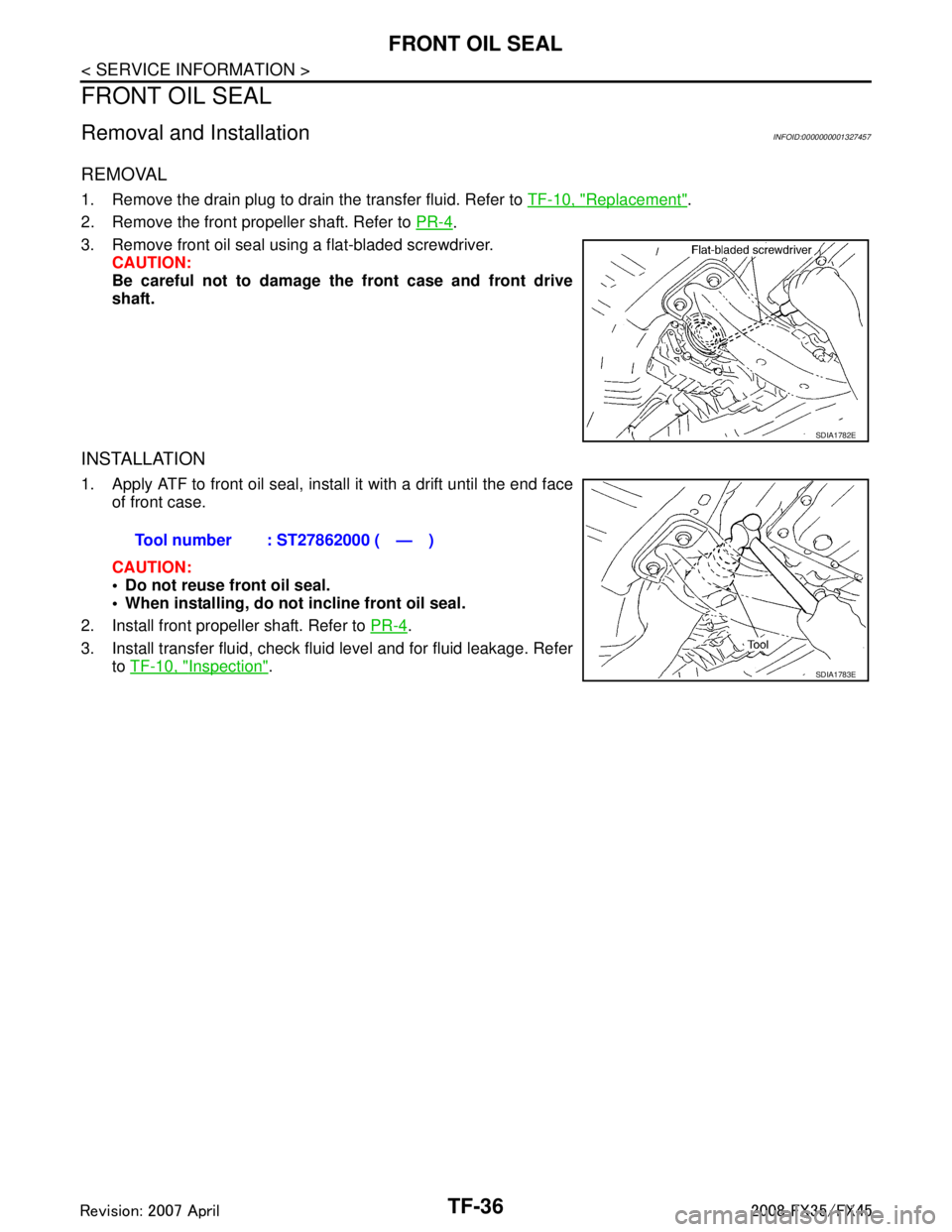
1. Remove the drain plug to drain the transfer fluid. Refer to TF-10, "Replacement".
2. Remove the front propeller shaft. Refer to PR-4
.
3. Remove front oil seal using a flat-bladed screwdriver. CAUTION:
Be careful not to damage the front case and front drive
shaft.
INSTALLATION
1. Apply ATF to front oil seal, install it with a drift until the end faceof front case.
CAUTION:
Do not reuse front oil seal.
When installing, do no t incline front oil seal.
2. Install front propeller shaft. Refer to PR-4
.
3. Install transfer fluid, check fluid level and for fluid leakage. Refer to TF-10, "
Inspection".
SDIA1782E
Tool number : ST27862000 ( — )
SDIA1783E
3AA93ABC3ACD3AC03ACA3AC03AC63AC53A913A773A893A873A873A8E3A773A983AC73AC93AC03AC3
3A893A873A873A8F3A773A9D3AAF3A8A3A8C3A863A9D3AAF3A8B3A8C
Page 3825 of 3924
AIR BREATHER HOSETF-39
< SERVICE INFORMATION >
CEF
G H
I
J
K L
M A
B
TF
N
O P
AIR BREATHER HOSE
Removal and InstallationINFOID:0000000001327459
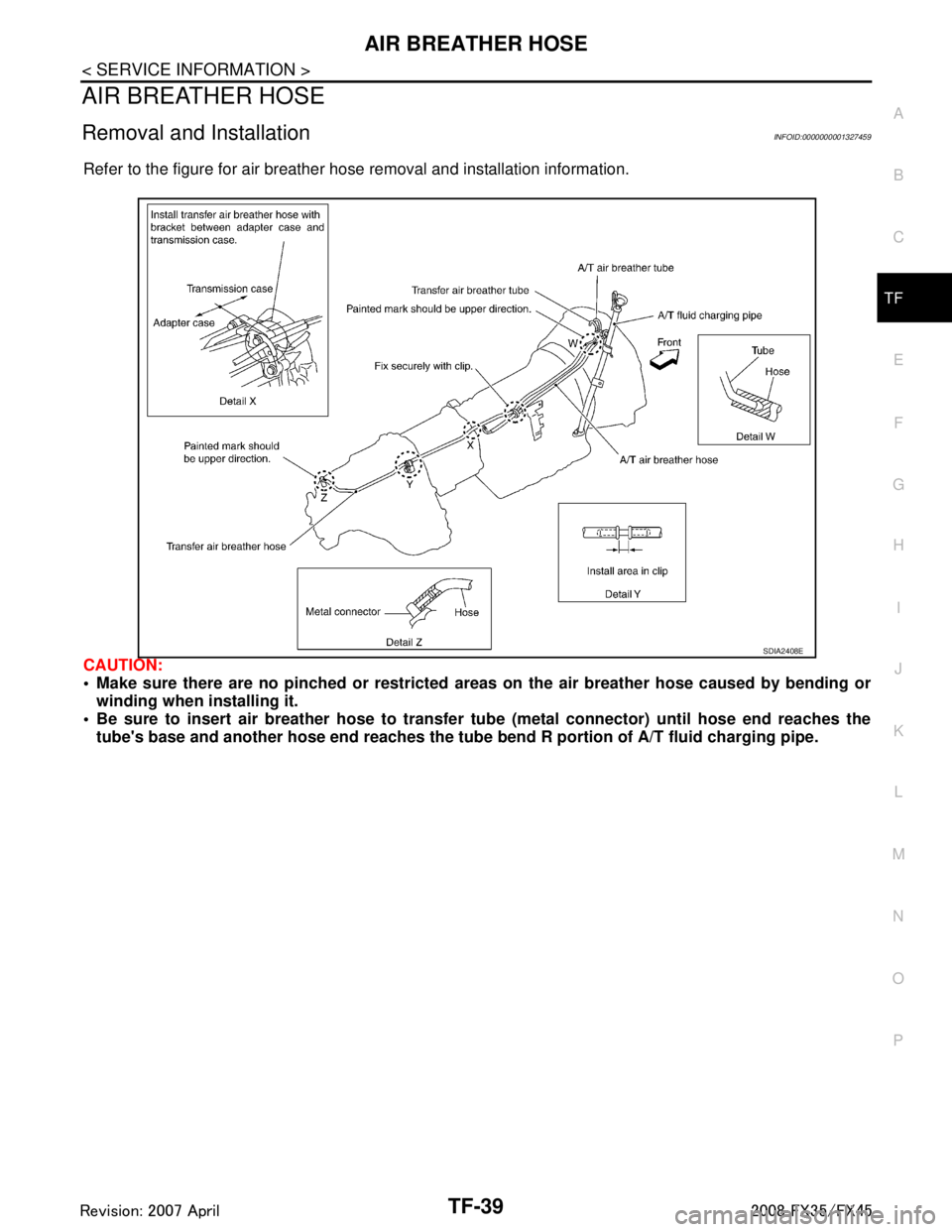
Refer to the figure for air breather hose removal and installation information.
CAUTION:
Make sure there are no pinched or restricted areas on the air breather hose caused by bending or
winding when installing it.
Be sure to insert air breather hose to transfer tube (metal connector) until hose end reaches the
tube's base and another hose end reaches the tube bend R portion of A/T fluid charging pipe.
SDIA2408E
3AA93ABC3ACD3AC03ACA3AC03AC63AC53A913A773A893A873A873A8E3A773A983AC73AC93AC03AC3
3A893A873A873A8F3A773A9D3AAF3A8A3A8C3A863A9D3AAF3A8B3A8C