2008 INFINITI FX35 transfer
[x] Cancel search: transferPage 2603 of 3924
![INFINITI FX35 2008 Service Manual
ENGINE ASSEMBLYEM-119
< SERVICE INFORMATION > [VQ35DE]
C
D
E
F
G H
I
J
K L
M A
EM
NP
O
2. Disconnect engine room harness connectors at unit sides TCM,
ECM and other.
3. Disengage intermediate fixing INFINITI FX35 2008 Service Manual
ENGINE ASSEMBLYEM-119
< SERVICE INFORMATION > [VQ35DE]
C
D
E
F
G H
I
J
K L
M A
EM
NP
O
2. Disconnect engine room harness connectors at unit sides TCM,
ECM and other.
3. Disengage intermediate fixing](/manual-img/42/57017/w960_57017-2602.png)
ENGINE ASSEMBLYEM-119
< SERVICE INFORMATION > [VQ35DE]
C
D
E
F
G H
I
J
K L
M A
EM
NP
O
2. Disconnect engine room harness connectors at unit sides TCM,
ECM and other.
3. Disengage intermediate fixing point. Pull out engine room harnesses to engine room side, and temporarily secure them on engine.
CAUTION:
When pulling out harnesses, take care no t to damage harnesses and connectors.
After temporarily securing, cover connectors with vi nyl or similar material to protect against for-
eign material adhesion.
Vehicle Underbody
1. Remove A/T fluid cooler hoses and pow er steering oil pump oil cooler hoses.
Install plug to avoid leakage of A/T fluid and power steering fluid.
2. Remove exhaust front tube and center muffler. Refer to EX-3, "
Checking Exhaust System".
3. Disconnect steering lower joint at power steering gear assembly side, and release steering lower shaft.
Refer to PS-12, "
Removal and Installation".
4. Remove tunnel stay. Refer to RSU-5, "
On-Vehicle Inspection and Service".
5. Remove rear propeller shaft. Refer to PR-7, "
On-Vehicle Inspection".
6. Remove front drive shaft (both side). Refer to FAX-13, "
On-Vehicle Inspection".
7. Disconnect harness connector from transmission assembly and transfer assembly.
8. Disengage A/T control rod at control device assembly side. Then, temporarily secure it on the transmis-
sion assembly, so that it does not sag. Refer to AT-205, "
Control Device Removal and Installation".
9. Remove rear plate from oil pan (upper). Then remove bolts fixing drive plate to torque converter. Refer to
EM-30, "
Component (2WD Models)" and AT-241, "Removal and Installation (2WD Models)".
10. Remove bolts fixing the transmission assembly to lower rear side of oil pan (upper). Refer to AT-241,
"Removal and Installation (2WD Models)".
11. Remove front stabilizer. Refer to FSU-15
.
12. Separate steering outer sockets from steering knuckle. Refer to PS-17, "
Removal and Installation".
13. Separate transverse links from suspension member and vehicle body. Refer to FSU-13, "
Removal and
Installation".
Removal Work
1. Use a manual lift table caddy (commercial service tool) or equiv-
alently rigid tool such as a transmission jack. Securely support
bottom of suspension member and transmission.
CAUTION:
Put a piece of wood or someth ing similar as the supporting
surface, secure a completely stable condition.
2. Remove rear engine mounting member bolts.
3. Remove front suspension member mounting nuts. Refer to FSU-5, "
On-Vehicle Inspection and Service".
4. Carefully lower jack, or raise lift to remove the engi ne, transmission assembly, transfer, front final drive
assembly and front suspension member. When per forming work, observe the following caution:
SBIA0473E
PBIC0804E
3AA93ABC3ACD3AC03ACA3AC03AC63AC53A913A773A893A873A873A8E3A773A983AC73AC93AC03AC3
3A893A873A873A8F3A773A9D3AAF3A8A3A8C3A863A9D3AAF3A8B3A8C
Page 2604 of 3924
![INFINITI FX35 2008 Service Manual
EM-120
< SERVICE INFORMATION >[VQ35DE]
ENGINE ASSEMBLY
CAUTION:
Confirm there is no interference with the vehicle.
Make sure that all connection
points have been disconnected.
Keep in mind the INFINITI FX35 2008 Service Manual
EM-120
< SERVICE INFORMATION >[VQ35DE]
ENGINE ASSEMBLY
CAUTION:
Confirm there is no interference with the vehicle.
Make sure that all connection
points have been disconnected.
Keep in mind the](/manual-img/42/57017/w960_57017-2603.png)
EM-120
< SERVICE INFORMATION >[VQ35DE]
ENGINE ASSEMBLY
CAUTION:
Confirm there is no interference with the vehicle.
Make sure that all connection
points have been disconnected.
Keep in mind the center of the vehicle gravity changes. If necessary, use jack(s) to support the
vehicle at rear jacking point(s) to pr event it from falling it off the lift.
Separation Work
1. Install engine slingers into front of cylinder head (right bank) and
rear of cylinder head (left bank).
To protect rocker cover against damage caused by tilting ofengine slinger, insert spacer between cylinder head and
engine rear lower slinger, in direction shown in the figure.
NOTE:
Spacer is a component part of engine rear upper slinger
assembly.
2. Remove power steering oil pump from engine side. Refer to PS-27, "
On-Vehicle Inspection and Service".
3. Remove engine mounting insulators (RH and LH) under side nuts with power tool.
4. Lift with hoist and separate the engine, the transmi ssion assembly, the transfer assembly and the front
final drive assembly from front suspension member.
CAUTION:
Before and during this lifting, always check if any harnesses are left connected.
Avoid damage to and oil/grease smearing or spills onto engine mounting insulator.
5. Remove alternator. Refer to SC-19, "
System Description".
6. Remove starter motor. Refer to SC-8
.
7. Remove front propeller shaft from the front final drive assembly side. Refer to PR-4, "
On-Vehicle Inspec-
tion".
8. Separate the engine from the transmission assembly. Refer to AT-241, "
Removal and Installation (2WD
Models)".
9. Remove the front final drive assembly from oil pan (upper). Refer to FFD-14, "
Removal and Installation
(VQ35DE Models)".
10. Remove each engine mounting insulator and each engine mounting bracket from the engine with power
tool.
11. Remove rear engine mounting member and engine m ounting insulator (rear) from the transmission
assembly.
12. Remove dynamic damper from the transfer assembly.
INSTALLATION
Note the following, and install in the reverse order of removal.
Do not allow engine mounting insulator to be damage and careful no engine oil gets on it.
For a location with a positioning pin, insert it securely into hole of mating part.
For a part with a specified installation orientation, refer to component figure in EM-117, "
Component (AWD
Models)".
Slinger bolts:
: 28.0 N·m (2.9 kg-m, 21 ft-lb)
PBIC2061E
KBIA1017E
3AA93ABC3ACD3AC03ACA3AC03AC63AC53A913A773A893A873A873A8E3A773A983AC73AC93AC03AC3
3A893A873A873A8F3A773A9D3AAF3A8A3A8C3A863A9D3AAF3A8B3A8C
Page 2607 of 3924
![INFINITI FX35 2008 Service Manual
CYLINDER BLOCKEM-123
< SERVICE INFORMATION > [VQ35DE]
C
D
E
F
G H
I
J
K L
M A
EM
NP
O
Refer to
GI-8, "Component" for symbols in the figure.
Disassembly and AssemblyINFOID:0000000001325747
DISASSEM INFINITI FX35 2008 Service Manual
CYLINDER BLOCKEM-123
< SERVICE INFORMATION > [VQ35DE]
C
D
E
F
G H
I
J
K L
M A
EM
NP
O
Refer to
GI-8, "Component" for symbols in the figure.
Disassembly and AssemblyINFOID:0000000001325747
DISASSEM](/manual-img/42/57017/w960_57017-2606.png)
CYLINDER BLOCKEM-123
< SERVICE INFORMATION > [VQ35DE]
C
D
E
F
G H
I
J
K L
M A
EM
NP
O
Refer to
GI-8, "Component" for symbols in the figure.
Disassembly and AssemblyINFOID:0000000001325747
DISASSEMBLY
1. Remove the engine assembly from the vehicle, and separate transmission assembly, transfer assembly
(AWD models), front final drive assembly (AWD models) and front suspension member from the engine.
Refer to EM-112, "
Component (2WD Models)".
2. Remove exhaust manifold. Refer to EM-26, "
Component".
3. Install engine sub-attachment with engine stand shaft (SST) to right side of cylinder block.
Use a spacer to the engine rear side.
10. Pilot converter 11. Main bearing 12. Crankshaft
13. Crankshaft key 14. Main bearing cap 15. Main bearing cap bolt
16. Main bearing beam 17. Baffle plate (2WD models) 18. Connecting rod bolt
19. Connecting rod bearing cap 20. Connecting rod bearing 21. Connecting rod
22. Snap ring 23. Piston pin 24. Piston
25. Oil ring 26. Second ring 27. Top ring
A. Refer to EM-123
B. Crankshaft side C. Chamfered
1. Cylinder block 2. Gasket 3. Water connector
4. Gasket 5. Cylinder block heater 6. Connector protector cap
PBIC2614E
SBIA0503E
3AA93ABC3ACD3AC03ACA3AC03AC63AC53A913A773A893A873A873A8E3A773A983AC73AC93AC03AC3
3A893A873A873A8F3A773A9D3AAF3A8A3A8C3A863A9D3AAF3A8B3A8C
Page 2708 of 3924
![INFINITI FX35 2008 Service Manual
EM-224
< SERVICE INFORMATION >[VK45DE]
OIL SEAL
Using front oil seal drift, press fit until the height of front oil seal
is level with the mounting surface.
Make sure the garter spring is in posi INFINITI FX35 2008 Service Manual
EM-224
< SERVICE INFORMATION >[VK45DE]
OIL SEAL
Using front oil seal drift, press fit until the height of front oil seal
is level with the mounting surface.
Make sure the garter spring is in posi](/manual-img/42/57017/w960_57017-2707.png)
EM-224
< SERVICE INFORMATION >[VK45DE]
OIL SEAL
Using front oil seal drift, press fit until the height of front oil seal
is level with the mounting surface.
Make sure the garter spring is in position and seal lips not inverted.
CAUTION:
Be careful not to damage front cover and oil pump drive spacer.
Press fit straight and avoid cau sing burrs or tilting oil seal.
3. Install in the reverse order of removal.
Removal and Installation of Rear Oil SealINFOID:0000000001325795
REMOVAL
1. Remove transmission (with transfer) assembly. Refer to AT-241, "Removal and Installation (2WD Mod-
els)".
a. Remove drive plate. Refer to EM-241, "
Component".
b. Remove engine rear plate. Refer to EM-241, "
Component".
2. Remove rear oil seal using suitable tool. CAUTION:
Be careful not to damage crankshaft and oil seal retainer
surface.
INSTALLATION
1. Apply new engine oil to both oil seal lip and dust seal lip of new rear oil seal.
2. Install rear oil seal. Install rear oil seal so that each seal lip is oriented as shown inthe figure.Front oil seal drift
Outer diameter : 56 mm (2.20 in)
Inner diameter : 49 mm (1.93 in)
SBIA0359E
SBIA0360E
SEM715A
3AA93ABC3ACD3AC03ACA3AC03AC63AC53A913A773A893A873A873A8E3A773A983AC73AC93AC03AC3
3A893A873A873A8F3A773A9D3AAF3A8A3A8C3A863A9D3AAF3A8B3A8C
Page 3318 of 3924

MA-1
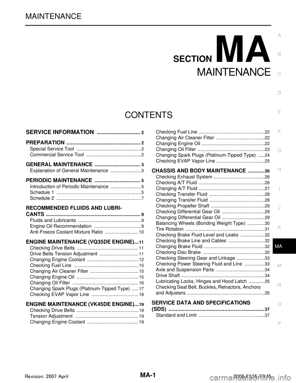
MAINTENANCE
C
DE
F
G H
I
J
K
M
SECTION MA
A
B
MA
N
O P
CONTENTS
MAINTENANCE
SERVICE INFORMATION .. ..........................2
PREPARATION .............................................. .....2
Special Service Tool ........................................... ......2
Commercial Service Tool ..........................................2
GENERAL MAINTENANCE ................................3
Explanation of General Maintenance .................. ......3
PERIODIC MAINTENANCE ................................5
Introduction of Periodic Maintenance .................. ......5
Schedule 1 ................................................................5
Schedule 2 ................................................................7
RECOMMENDED FLUIDS AND LUBRI-
CANTS .................................................................
9
Fluids and Lubricants .......................................... ......9
Engine Oil Recommendation ....................................9
Anti-Freeze Coolant Mixture Ratio ..........................10
ENGINE MAINTENANCE (VQ35DE ENGINE) ....11
Checking Drive Belts ........................................... ....11
Drive Belts Tension Adjustment ..............................11
Changing Engine Coolant .......................................12
Checking Fuel Line .................................................15
Changing Air Cleaner Filter .....................................15
Changing Engine Oil ...............................................15
Changing Oil Filter ..................................................16
Changing Spark Plugs (Platinum-Tipped Type) ......17
Checking EVAP Vapor Line ....................................18
ENGINE MAINTENANCE (VK45DE ENGINE) ....19
Checking Drive Belts ........................................... ....19
Tension Adjustment ................................................19
Changing Engine Coolant .......................................19
Checking Fuel Line .............................................. ....22
Changing Air Cleaner Filter .....................................22
Changing Engine Oil ................................................22
Changing Oil Filter ...................................................23
Changing Spark Plugs (Platinum-Tipped Type) ......24
Checking EVAP Vapor Line .....................................25
CHASSIS AND BODY MAINTENANCE ...........26
Checking Exhaust System ................................... ....26
Checking A/T Fluid ..................................................26
Changing A/T Fluid ..................................................27
Checking Transfer Fluid ..........................................28
Changing Transfer Fluid ..........................................28
Checking Propeller Shaft .........................................29
Checking Differential Gear Oil .................................29
Changing Differential Gear Oil .................................29
Balancing Wheels (Bonding Weight Type) ..............30
Tire Rotation ............................................................31
Checking Brake Fluid Level and Leaks ...................32
Checking Brake Line and Cables ............................32
Changing Brake Fluid ..............................................32
Checking Disc Brake ...............................................32
Checking Steering Gear and Linkage ......................33
Checking Power Steering Fluid and Line ................33
Axle and Suspension Parts .....................................34
Drive Shaft ...............................................................34
Lubricating Locks, Hinges and Hood Latch .............35
Checking Seat Belt, Buckles, Retractors, Anchors
and Adjusters ...........................................................
35
SERVICE DATA AND SPECIFICATIONS
(SDS) .................................................................
37
Standard and Limit ..................................................37
3AA93ABC3ACD3AC03ACA3AC03AC63AC53A913A773A893A873A873A8E3A773A983AC73AC93AC03AC3
3A893A873A873A8F3A773A9D3AAF3A8A3A8C3A863A9D3AAF3A8B3A8C
Page 3323 of 3924

MA-6
< SERVICE INFORMATION >
PERIODIC MAINTENANCE
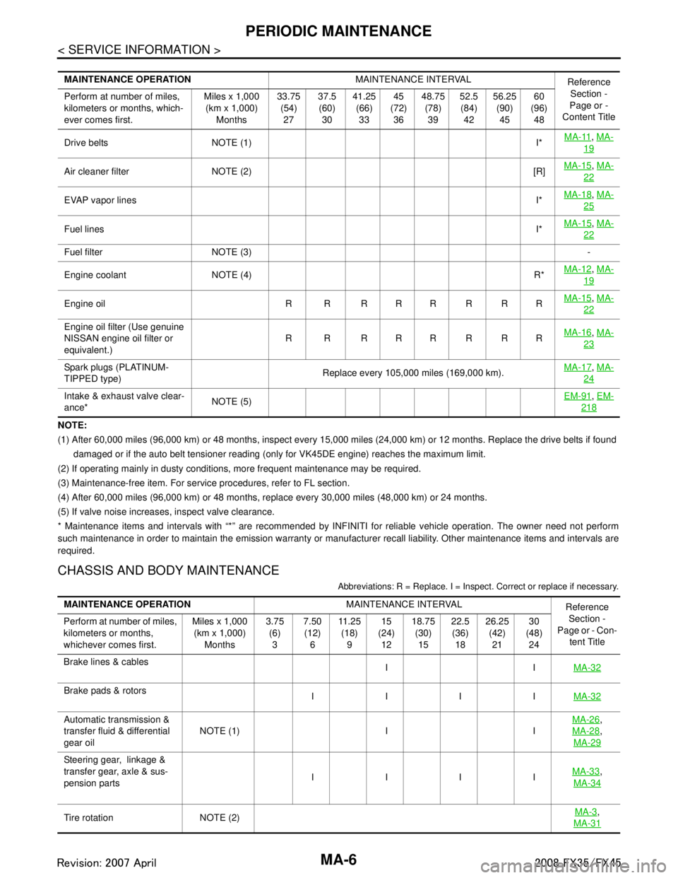
NOTE:
(1) After 60,000 miles (96,000 km) or 48 months, inspect every 15,000 miles (24,000 km) or 12 months. Replace the drive belts if found
damaged or if the auto belt tensioner reading (only for VK45DE engine) reaches the maximum limit.
(2) If operating mainly in dusty conditions, more frequent maintenance may be required.
(3) Maintenance-free item. For service procedures, refer to FL section.
(4) After 60,000 miles (96,000 km) or 48 months, replace every 30,000 miles (48,000 km) or 24 months.
(5) If valve noise increases, inspect valve clearance.
* Maintenance items and intervals with “*” are recommended by INFINITI for reliable vehicle operation. The owner need not perfo rm
such maintenance in order to maintain the emission warranty or manufacturer recall liability. Other maintenance items and inter vals are
required.
CHASSIS AND BODY MAINTENANCE
Abbreviations: R = Replace. I = Inspec t. Correct or replace if necessary.
MAINTENANCE OPERATION MAINTENANCE INTERVAL
Reference
Section -
Page or -
Content Title
Perform at number of miles,
kilometers or months, which-
ever comes first. Miles x 1,000
(km x 1,000) Months 33.75
(54)27 37.5
(60) 30 41.25
(66)33 45
(72) 36 48.75
(78)39 52.5
(84) 42 56.25
(90)45 60
(96) 48
Drive belts NOTE (1) I* MA-11
,
MA-
19
Air cleaner filter NOTE (2) [R] MA-15,
MA-
22
EVAP vapor lines I*MA-18,
MA-
25
Fuel lines I*MA-15,
MA-
22
Fuel filter NOTE (3) -
Engine coolant NOTE (4) R* MA-12
,
MA-
19
Engine oil R R R R R R R R MA-15,
MA-
22
Engine oil filter (Use genuine
NISSAN engine oil filter or
equivalent.) R R RRRRRR
MA-16,
MA-
23
Spark plugs (PLATINUM-
TIPPED type) Replace every 105,000 miles (169,000 km).MA-17,
MA-
24
Intake & exhaust valve clear-
ance* NOTE (5) EM-91,
EM-
218
MAINTENANCE OPERATION MAINTENANCE INTERVAL
Reference
Section -
Page or - Con-
tent Title
Perform at number of miles,
kilometers or months,
whichever comes first. Miles x 1,000
(km x 1,000) Months 3.75
(6)3 7.50
(12) 6 11 . 2 5
(18) 9 15
(24) 12 18.75
(30)15 22.5
(36) 18 26.25
(42)21 30
(48) 24
Brake lines & cables IIMA-32
Brake pads & rotors
IIII MA-32
Automatic transmission &
transfer fluid & differential
gear oilNOTE (1) I I MA-26,
MA-28
,
MA-29
Steering gear, linkage &
transfer gear, axle & sus-
pension parts IIII
MA-33
,
MA-34
Tire rotation NOTE (2) MA-3,
MA-31
3AA93ABC3ACD3AC03ACA3AC03AC63AC53A913A773A893A873A873A8E3A773A983AC73AC93AC03AC3
3A893A873A873A8F3A773A9D3AAF3A8A3A8C3A863A9D3AAF3A8B3A8C
Page 3324 of 3924

PERIODIC MAINTENANCEMA-7
< SERVICE INFORMATION >
C
DE
F
G H
I
J
K
M A
B
MA
N
O P
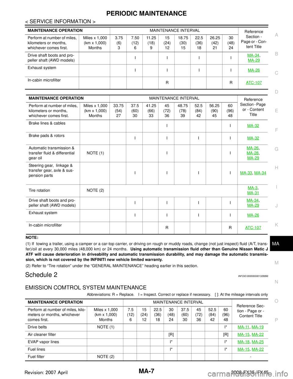
NOTE:
(1) If towing a trailer, using a camper or a car-top carrier, or driving on rough or muddy roads, change (not just inspect) fl uid (A/T, trans-
fer)/oil at every 30,000 miles (48,000 km) or 24 months. Using automatic transmission fluid other than Genuine Nissan Matic J
ATF will cause deterioration in driveability and automatic transmission durability, and may damage the automatic transmis-
sion, which is not covered by the INFINITI new vehicle limited warranty.
(2) Refer to “Tire rotation” under the “GENERAL MAINTENANCE” heading earlier in this section.
Schedule 2INFOID:0000000001328896
EMISSION COMTROL SYSTEM MAINTENANCE
Abbreviations: R = Replace. I = Inspect. Correct or r eplace if necessary. [ ]: At the mileage intervals only
Drive shaft boots and pro-
peller shaft (AWD models) IIII
MA-34,
MA-29
Exhaust system IIII MA-26
In-cabin microfilter
RRAT C - 1 0 7
MAINTENANCE OPERATION MAINTENANCE INTERVAL
Reference
Section -
Page or - Con- tent Title
Perform at number of miles,
kilometers or months,
whichever comes first. Miles x 1,000
(km x 1,000)
Months 3.75
(6)
3 7.50
(12)
6 11 . 2 5
(18)
9 15
(24)
12 18.75
(30)
15 22.5
(36)
18 26.25
(42)
21 30
(48)
24
MAINTENANCE OPERATION MAINTENANCE INTERVAL
Reference
Section - Page
or - Content Title
Perform at number of miles,
kilometers or months,
whichever comes first. Miles x 1,000
(km x 1,000) Months 33.75
(54)27 37.5
(60) 30 41.25
(66)33 45
(72) 36 48.75
(78)39 52.5
(84) 42 56.25
(90)45 60
(96) 48
Brake lines & cables IIMA-32
Brake pads & rotors
IIII MA-32
Automatic transmission &
transfer fluid & differential
gear oilNOTE (1) I I
MA-26,
MA-28
,
MA-29
Steering gear, linkage &
transfer gear, axle & sus-
pension parts IIII
MA-33
, MA-34
Tire rotation NOTE (2) MA-3,
MA-31
Drive shaft boots and pro-
peller shaft (AWD models) IIII MA-34,
MA-29
Exhaust system IIII MA-26
In-cabin microfilter
RRAT C - 1 0 7
MAINTENANCE OPERATION MAINTENANCE INTERVAL
Reference Sec-
tion - Page or - Content Title
Perform at number of miles, kilo-
meters or months, whichever
comes first. Miles x 1,000
(km x 1,000) Months 7.5
(12) 6 15
(24) 12 22.5
(36) 18 30
(48) 24 37.5
(60) 30 45
(72) 36 52.5
(84) 42 60
(96) 48
Drive belts NOTE (1) I* MA-11
, MA-19
Air cleaner filter [R] [R] MA-15, MA-22
EVAP vapor lines I* I* MA-18, MA-25
Fuel lines I* I* MA-15, MA-22
Fuel filter NOTE (2) -
3AA93ABC3ACD3AC03ACA3AC03AC63AC53A913A773A893A873A873A8E3A773A983AC73AC93AC03AC3
3A893A873A873A8F3A773A9D3AAF3A8A3A8C3A863A9D3AAF3A8B3A8C
Page 3325 of 3924

MA-8
< SERVICE INFORMATION >
PERIODIC MAINTENANCE
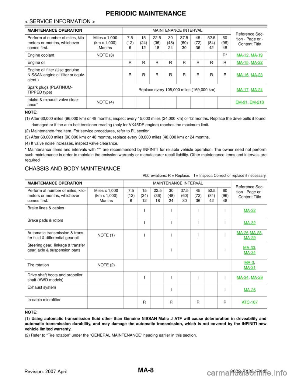
NOTE:
(1) After 60,000 miles (96,000 km) or 48 months, inspect every 15,000 miles (24,000 km) or 12 months. Replace the drive belts if found
damaged or if the auto belt tensioner reading (only for VK45DE engine) reaches the maximum limit.
(2) Maintenance-free item. For service procedures, refer to FL section.
(3) After 60,000 miles (96,000 km) or 48 months, replace every 30,000 miles (48,000 km) or 24 months.
(4) If valve noise increases, inspect valve clearance.
* Maintenance items and intervals with “*” are recommended by INFINITI for reliable vehicle operation. The owner need not perfo rm
such maintenance in order to maintain the emission warranty or manufacturer recall liability. Other maintenance items and inter vals are
required
CHASSIS AND BODY MAINTENANCE
Abbreviations: R = Replace. I = Inspec t. Correct or replace if necessary.
NOTE:
(1) Using automatic transmission fluid other than Genuine NISSAN Matic J ATF will cause deterioration in driveability and
automatic transmission durability, and may damage the automatic transmission, which is not covered by the INFINITI new
vehicle limited warranty.
(2) Refer to “Tire rotation” under the “GENERAL MAINTENANCE” heading earlier in this section.
Engine coolant NOTE (3) R*
MA-12
, MA-19
Engine oil R R R R R R R R MA-15, MA-22
Engine oil filter (Use genuine
NISSAN engine oil filter or equiv-
alent.) RRRR R RRR
MA-16
, MA-23
Spark plugs (PLATINUM-
TIPPED type) Replace every 105,000 miles (169,000 km).
MA-17, MA-24
Intake & exhaust valve clear-
ance* NOTE (4)
EM-91, EM-218
MAINTENANCE OPERATION MAINTENANCE INTERVAL
Reference Sec-
tion - Page or -
Content Title
Perform at number of miles, kilo-
meters or months, whichever
comes first. Miles x 1,000
(km x 1,000)
Months 7.5
(12)
6 15
(24)
12 22.5
(36)
18 30
(48)
24 37.5
(60)
30 45
(72)
36 52.5
(84)
42 60
(96)
48
MAINTENANCE OPERATION MAINTENANCE INTERVAL
Reference Sec-
tion - Page or - Content Title
Perform at number of miles, kilo-
meters or months, whichever
comes first. Miles x 1,000
(km x 1,000) Months 7.5
(12) 6 15
(24) 12 22.5
(36) 18 30
(48) 24 37.5
(60) 30 45
(72) 36 52.5
(84) 42 60
(96) 48
Brake lines & cables IIIIMA-32
Brake pads & rotors
IIIIMA-32
Automatic transmission & trans-
fer fluid & differential gear oilNOTE (1) IIII MA-26,
MA-28,
MA-29
Steering gear, linkage & transfer
gear, axle & suspension parts I I MA-33,
MA-34
Tire rotation NOTE (2) MA-3,
MA-31
Drive shaft boots and propeller
shaft (AWD models) IIII
MA-34, MA-29
Exhaust system
IIMA-26
In-cabin microfilter
RRRRAT C - 1 0 7
3AA93ABC3ACD3AC03ACA3AC03AC63AC53A913A773A893A873A873A8E3A773A983AC73AC93AC03AC3
3A893A873A873A8F3A773A9D3AAF3A8A3A8C3A863A9D3AAF3A8B3A8C