Page 167 of 3000
AH–10AXLE – FRONT AXLE HUB
AH
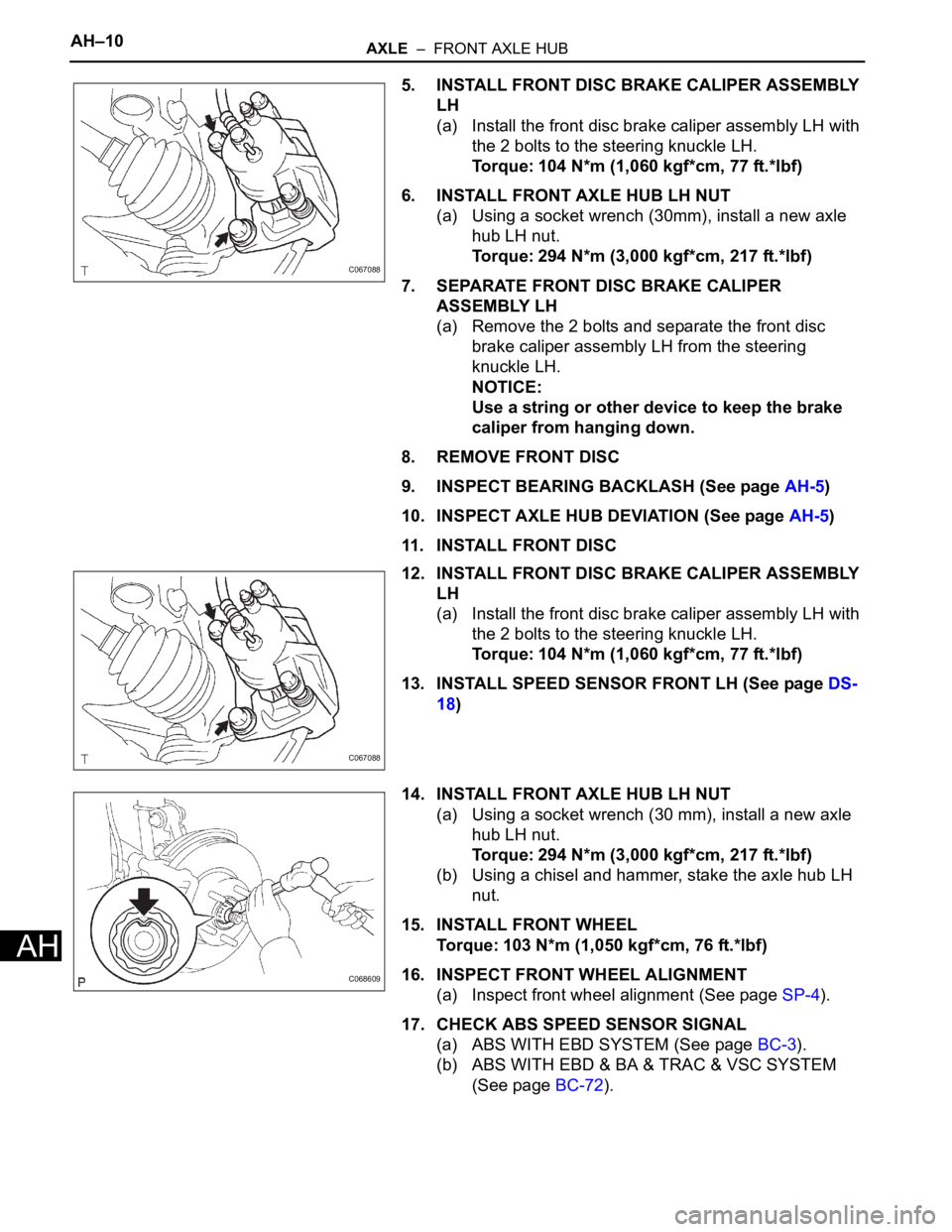
5. INSTALL FRONT DISC BRAKE CALIPER ASSEMBLY
LH
(a) Install the front disc brake caliper assembly LH with
the 2 bolts to the steering knuckle LH.
Torque: 104 N*m (1,060 kgf*cm, 77 ft.*lbf)
6. INSTALL FRONT AXLE HUB LH NUT
(a) Using a socket wrench (30mm), install a new axle
hub LH nut.
Torque: 294 N*m (3,000 kgf*cm, 217 ft.*lbf)
7. SEPARATE FRONT DISC BRAKE CALIPER
ASSEMBLY LH
(a) Remove the 2 bolts and separate the front disc
brake caliper assembly LH from the steering
knuckle LH.
NOTICE:
Use a string or other device to keep the brake
caliper from hanging down.
8. REMOVE FRONT DISC
9. INSPECT BEARING BACKLASH (See page AH-5)
10. INSPECT AXLE HUB DEVIATION (See page AH-5)
11. INSTALL FRONT DISC
12. INSTALL FRONT DISC BRAKE CALIPER ASSEMBLY
LH
(a) Install the front disc brake caliper assembly LH with
the 2 bolts to the steering knuckle LH.
Torque: 104 N*m (1,060 kgf*cm, 77 ft.*lbf)
13. INSTALL SPEED SENSOR FRONT LH (See page DS-
18)
14. INSTALL FRONT AXLE HUB LH NUT
(a) Using a socket wrench (30 mm), install a new axle
hub LH nut.
Torque: 294 N*m (3,000 kgf*cm, 217 ft.*lbf)
(b) Using a chisel and hammer, stake the axle hub LH
nut.
15. INSTALL FRONT WHEEL
Torque: 103 N*m (1,050 kgf*cm, 76 ft.*lbf)
16. INSPECT FRONT WHEEL ALIGNMENT
(a) Inspect front wheel alignment (See page SP-4).
17. CHECK ABS SPEED SENSOR SIGNAL
(a) ABS WITH EBD SYSTEM (See page BC-3).
(b) ABS WITH EBD & BA & TRAC & VSC SYSTEM
(See page BC-72).
C067088
C067088
C068609
Page 2160 of 3000
AH–18AXLE – REAR AXLE HUB AND BEARING (for 2WD)
AH
7. INSTALL REAR DISC BRAKE CALIPER ASSEMBLY
LH
(a) Install the rear disc brake caliper assembly LH with
the 2 bolts for disc rear brake type.
Torque: 88 N*m (900 kgf*cm, 65 ft.*lbf)
8. INSTALL REAR WHEEL
Torque: 103 N*m (1,050 kgf*cm, 76 ft.*lbf)
9. CHECK ABS SPEED SENSOR SIGNAL
(a) ABS WITH EBD SYSTEM (See page BC-3).
(b) ABS WITH EBD & BA & TRAC & VSC SYSTEM
(See page BC-72).
Page 2162 of 3000
AXLE – REAR AXLE HUB AND BEARING (for 4WD)AH–21
AH
• Do not twist the sensor wire when installing
the sensor.
6. INSTALL REAR DISC
7. INSTALL REAR DISC BRAKE CALIPER ASSEMBLY
LH
(a) Install the rear disc brake caliper assembly LH with
the 2 bolts.
Torque: 88 N*m (900 kgf*cm, 65 ft.*lbf)
8. INSTALL REAR AXLE SHAFT LH NUT (See page DS-
26)
9. INSTALL REAR WHEEL
Torque: 103 N*m (1,050 kgf*cm, 76 ft.*lbf)
10. CHECK ABS SPEED SENSOR SIGNAL
(a) ABS WITH EBD & BA & TRAC & VSC SYSTEM
(See page BC-72).
Page 2169 of 3000
AH–10AXLE – FRONT AXLE HUB
AH
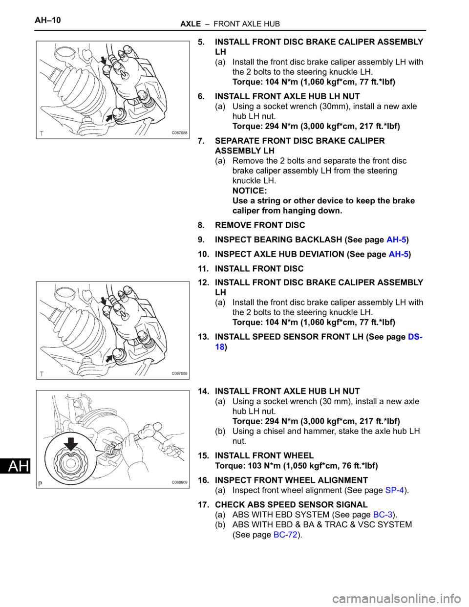
5. INSTALL FRONT DISC BRAKE CALIPER ASSEMBLY
LH
(a) Install the front disc brake caliper assembly LH with
the 2 bolts to the steering knuckle LH.
Torque: 104 N*m (1,060 kgf*cm, 77 ft.*lbf)
6. INSTALL FRONT AXLE HUB LH NUT
(a) Using a socket wrench (30mm), install a new axle
hub LH nut.
Torque: 294 N*m (3,000 kgf*cm, 217 ft.*lbf)
7. SEPARATE FRONT DISC BRAKE CALIPER
ASSEMBLY LH
(a) Remove the 2 bolts and separate the front disc
brake caliper assembly LH from the steering
knuckle LH.
NOTICE:
Use a string or other device to keep the brake
caliper from hanging down.
8. REMOVE FRONT DISC
9. INSPECT BEARING BACKLASH (See page AH-5)
10. INSPECT AXLE HUB DEVIATION (See page AH-5)
11. INSTALL FRONT DISC
12. INSTALL FRONT DISC BRAKE CALIPER ASSEMBLY
LH
(a) Install the front disc brake caliper assembly LH with
the 2 bolts to the steering knuckle LH.
Torque: 104 N*m (1,060 kgf*cm, 77 ft.*lbf)
13. INSTALL SPEED SENSOR FRONT LH (See page DS-
18)
14. INSTALL FRONT AXLE HUB LH NUT
(a) Using a socket wrench (30 mm), install a new axle
hub LH nut.
Torque: 294 N*m (3,000 kgf*cm, 217 ft.*lbf)
(b) Using a chisel and hammer, stake the axle hub LH
nut.
15. INSTALL FRONT WHEEL
Torque: 103 N*m (1,050 kgf*cm, 76 ft.*lbf)
16. INSPECT FRONT WHEEL ALIGNMENT
(a) Inspect front wheel alignment (See page SP-4).
17. CHECK ABS SPEED SENSOR SIGNAL
(a) ABS WITH EBD SYSTEM (See page BC-3).
(b) ABS WITH EBD & BA & TRAC & VSC SYSTEM
(See page BC-72).
C067088
C067088
C068609
Page 2173 of 3000
AH–18AXLE – REAR AXLE HUB AND BEARING (for 2WD)
AH
7. INSTALL REAR DISC BRAKE CALIPER ASSEMBLY
LH
(a) Install the rear disc brake caliper assembly LH with
the 2 bolts for disc rear brake type.
Torque: 88 N*m (900 kgf*cm, 65 ft.*lbf)
8. INSTALL REAR WHEEL
Torque: 103 N*m (1,050 kgf*cm, 76 ft.*lbf)
9. CHECK ABS SPEED SENSOR SIGNAL
(a) ABS WITH EBD SYSTEM (See page BC-3).
(b) ABS WITH EBD & BA & TRAC & VSC SYSTEM
(See page BC-72).
Page 2177 of 3000
AXLE – REAR AXLE HUB AND BEARING (for 4WD)AH–21
AH
• Do not twist the sensor wire when installing
the sensor.
6. INSTALL REAR DISC
7. INSTALL REAR DISC BRAKE CALIPER ASSEMBLY
LH
(a) Install the rear disc brake caliper assembly LH with
the 2 bolts.
Torque: 88 N*m (900 kgf*cm, 65 ft.*lbf)
8. INSTALL REAR AXLE SHAFT LH NUT (See page DS-
26)
9. INSTALL REAR WHEEL
Torque: 103 N*m (1,050 kgf*cm, 76 ft.*lbf)
10. CHECK ABS SPEED SENSOR SIGNAL
(a) ABS WITH EBD & BA & TRAC & VSC SYSTEM
(See page BC-72).
Page 2186 of 3000
SP–4SUSPENSION – FRONT WHEEL ALIGNMENT
SP
FRONT WHEEL ALIGNMENT
ADJUSTMENT
NOTICE:
For vehicles equipped with VSC, if wheel alignment has
been adjusted, and if suspension or underbody
components have been removed/installed or replaced, be
sure to perform the following initialization procedure in
order for the system to function normally:
1. Disconnect the negative battery terminal for more
than 2 seconds.
2. Reconnect the negative battery terminal.
3. Perform zero point calibration of the yaw rate and
acceleration sensor and test mode inspection.
HINT:
(See page BC-70)
1. INSPECT TIRE
HINT:
(See page TW-2)
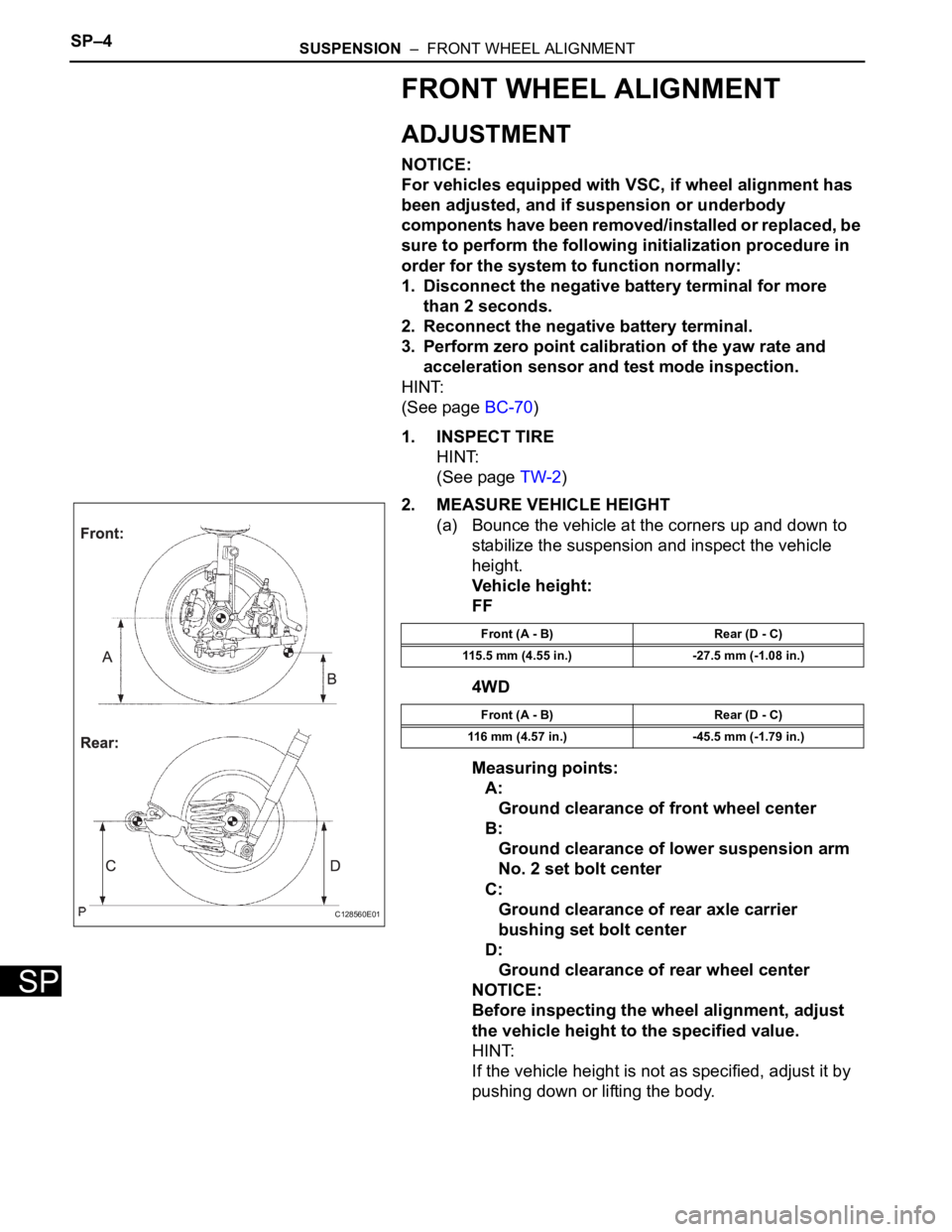
2. MEASURE VEHICLE HEIGHT
(a) Bounce the vehicle at the corners up and down to
stabilize the suspension and inspect the vehicle
height.
Vehicle height:
FF
4WD
Measuring points:
A:
Ground clearance of front wheel center
B:
Ground clearance of lower suspension arm
No. 2 set bolt center
C:
Ground clearance of rear axle carrier
bushing set bolt center
D:
Ground clearance of rear wheel center
NOTICE:
Before inspecting the wheel alignment, adjust
the vehicle height to the specified value.
HINT:
If the vehicle height is not as specified, adjust it by
pushing down or lifting the body.
C128560E01
Front (A - B) Rear (D - C)
115.5 mm (4.55 in.) -27.5 mm (-1.08 in.)
Front (A - B) Rear (D - C)
116 mm (4.57 in.) -45.5 mm (-1.79 in.)
Page 2192 of 3000
SUSPENSION – REAR WHEEL ALIGNMENTSP–9
SP
REAR WHEEL ALIGNMENT
ADJUSTMENT
NOTICE:
For vehicles equipped with VSC, if wheel alignment has
been adjusted, and if suspension or underbody
components have been removed/installed or replaced, be
sure to perform the following initialization procedure in
order for the system to function normally:
1. Disconnect the negative battery terminal for more
than 2 seconds.
2. Reconnect the negative battery terminal.
3. Perform zero point calibration of the yaw rate and
acceleration sensor and test mode inspection.
HINT:
(See page BC-70)
1. INSPECT TIRE
HINT:
(See page TW-2)
2. MEASURE VEHICLE HEIGHT
NOTICE:
Before inspecting the wheel alignment, adjust the
vehicle height to the specified valve.
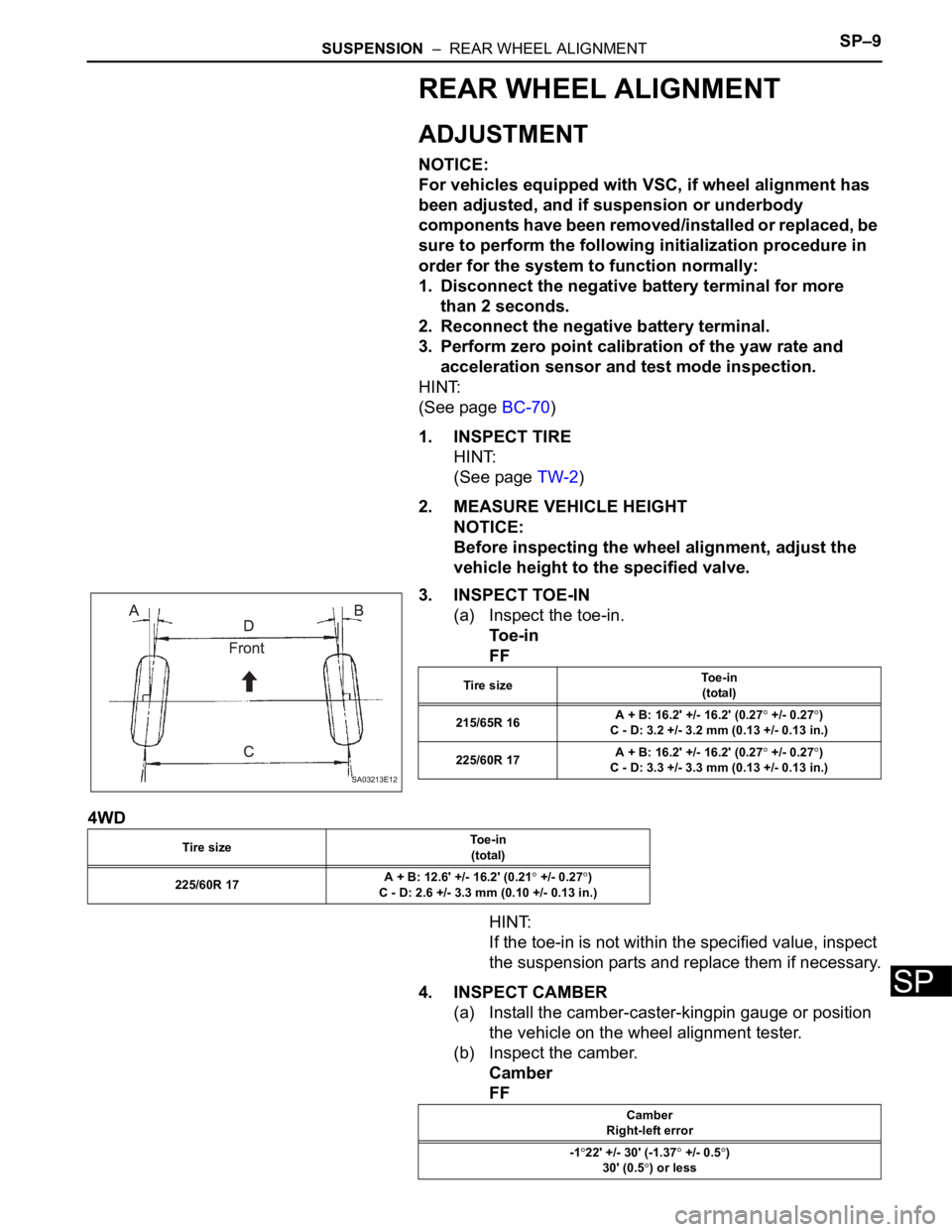
3. INSPECT TOE-IN
(a) Inspect the toe-in.
To e - i n
FF
4WD
HINT:
If the toe-in is not within the specified value, inspect
the suspension parts and replace them if necessary.
4. INSPECT CAMBER
(a) Install the camber-caster-kingpin gauge or position
the vehicle on the wheel alignment tester.
(b) Inspect the camber.
Camber
FF
SA03213E12
Tire sizeTo e - i n
(total)
215/65R 16A + B: 16.2' +/- 16.2' (0.27
+/- 0.27)
C - D: 3.2 +/- 3.2 mm (0.13 +/- 0.13 in.)
225/60R 17A + B: 16.2' +/- 16.2' (0.27
+/- 0.27)
C - D: 3.3 +/- 3.3 mm (0.13 +/- 0.13 in.)
Tire sizeTo e - i n
(total)
225/60R 17A + B: 12.6' +/- 16.2' (0.21
+/- 0.27)
C - D: 2.6 +/- 3.3 mm (0.10 +/- 0.13 in.)
Camber
Right-left error
-1
22' +/- 30' (-1.37 +/- 0.5)
30' (0.5
) or less