2007 TOYOTA SIENNA c0205
[x] Cancel search: c0205Page 2373 of 3000

BRAKE CONTROL – ANTI-LOCK BRAKE SYSTEMBC–25
BC
DESCRIPTION
Refer to DTCs C0200/31, C0205/32, C1235/35, and C1236/36 (See page BC-17).
DTCs C1273/73 to C1278/78 can be deleted when the speed sensor sends a vehicle speed signal or the
Test Mode ends. DTCs C1273/73 to C1278/78 are output only in the Test Mode.
HINT:
• DTC C0210/33 and C1238/38 are for the rear speed sensor RH.
• DTC C0215/34 and C1239/39 are for the rear speed sensor LH.
DTC C0210/33 Rear Speed Sensor RH Circuit
DTC C0215/34 Rear Speed Sensor LH Circuit
DTC C1238/38Foreign Object is Attached on Tip of Rear
Speed Sensor RH
DTC C1239/39Foreign Object is Attached on Tip of Rear
Speed Sensor LH
DTC C1273/73Low Output Signal of Rear Speed Sensor RH
(Test Mode DTC)
DTC C1274/74Low Output Signal of Rear Speed Sensor LH
(Test Mode DTC)
DTC C1277/77Abnormal Change in Output Signal of Rear
Speed Sensor RH (Test Mode DTC)
DTC C1278/78Abnormal Change in Output Signal of Rear
Speed Sensor LH (Test Mode DTC)
DTC No. DTC Detection Condition Trouble Area
C0210/33
C0215/34With vehicle speed at 10 km/h (6 mph) or more, sensor
signal circuit of faulty wheel is open or short for 1
second or more.
• Momentary interruption of sensor signal of faulty
wheel has occurred 7 times or more.
• Sensor signal circuit is open for 0.5 seconds or
more.• Rear speed sensor RH/LH
• Rear speed sensor RH/LH circuit
• Speed sensor rotor
• Sensor installation
• Brake actuator assembly
C1238/38
C1239/39At vehicle speed of 20 km/h (12 mph) or more, condition
that noise is included in speed sensor signal continues
for 5 seconds or more.• Rear speed sensor RH/LH
• Speed sensor rotor
• Sensor installation
• Brake actuator assembly
Page 2384 of 3000
BRAKE CONTROL – ANTI-LOCK BRAKE SYSTEMBC–17
BC
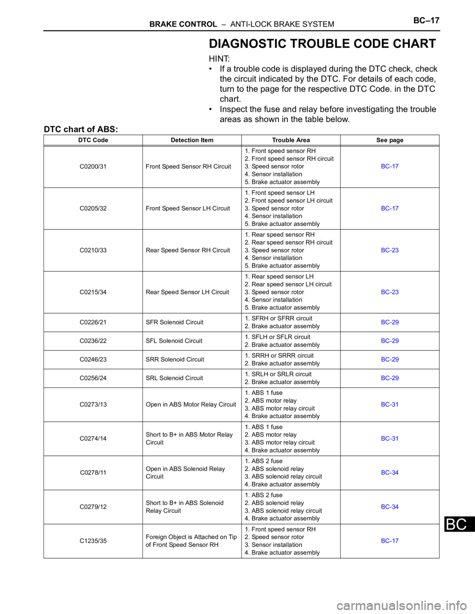
DIAGNOSTIC TROUBLE CODE CHART
HINT:
• If a trouble code is displayed during the DTC check, check
the circuit indicated by the DTC. For details of each code,
turn to the page for the respective DTC Code. in the DTC
chart.
• Inspect the fuse and relay before investigating the trouble
areas as shown in the table below.
DTC chart of ABS:
DTC Code Detection Item Trouble Area See page
C0200/31 Front Speed Sensor RH Circuit1. Front speed sensor RH
2. Front speed sensor RH circuit
3. Speed sensor rotor
4. Sensor installation
5. Brake actuator assemblyBC-17
C0205/32 Front Speed Sensor LH Circuit1. Front speed sensor LH
2. Front speed sensor LH circuit
3. Speed sensor rotor
4. Sensor installation
5. Brake actuator assemblyBC-17
C0210/33 Rear Speed Sensor RH Circuit1. Rear speed sensor RH
2. Rear speed sensor RH circuit
3. Speed sensor rotor
4. Sensor installation
5. Brake actuator assemblyBC-23
C0215/34 Rear Speed Sensor LH Circuit1. Rear speed sensor LH
2. Rear speed sensor LH circuit
3. Speed sensor rotor
4. Sensor installation
5. Brake actuator assemblyBC-23
C0226/21 SFR Solenoid Circuit1. SFRH or SFRR circuit
2. Brake actuator assemblyBC-29
C0236/22 SFL Solenoid Circuit1. SFLH or SFLR circuit
2. Brake actuator assemblyBC-29
C0246/23 SRR Solenoid Circuit1. SRRH or SRRR circuit
2. Brake actuator assemblyBC-29
C0256/24 SRL Solenoid Circuit1. SRLH or SRLR circuit
2. Brake actuator assemblyBC-29
C0273/13 Open in ABS Motor Relay Circuit1. ABS 1 fuse
2. ABS motor relay
3. ABS motor relay circuit
4. Brake actuator assemblyBC-31
C0274/14Short to B+ in ABS Motor Relay
Circuit1. ABS 1 fuse
2. ABS motor relay
3. ABS motor relay circuit
4. Brake actuator assemblyBC-31
C0278/11Open in ABS Solenoid Relay
Circuit1. ABS 2 fuse
2. ABS solenoid relay
3. ABS solenoid relay circuit
4. Brake actuator assemblyBC-34
C0279/12Short to B+ in ABS Solenoid
Relay Circuit1. ABS 2 fuse
2. ABS solenoid relay
3. ABS solenoid relay circuit
4. Brake actuator assemblyBC-34
C1235/35Foreign Object is Attached on Tip
of Front Speed Sensor RH1. Front speed sensor RH
2. Speed sensor rotor
3. Sensor installation
4. Brake actuator assemblyBC-17
Page 2386 of 3000
BRAKE CONTROL – ANTI-LOCK BRAKE SYSTEMBC–19
BC
DESCRIPTION
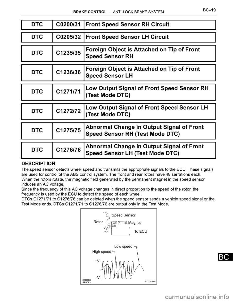
The speed sensor detects wheel speed and transmits the appropriate signals to the ECU. These signals
are used for control of the ABS control system. The front and rear rotors have 48 serrations each.
When the rotors rotate, the magnetic field generated by the permanent magnet in the speed sensor
induces an AC voltage.
Since the frequency of this AC voltage changes in direct proportion to the speed of the rotor, the
frequency is used by the ECU to detect the speed of each wheel.
DTCs C1271/71 to C1276/76 can be deleted when the speed sensor sends a vehicle speed signal or the
Test Mode ends. DTCs C1271/71 to C1276/76 are output only in the Test Mode.
DTC C0200/31 Front Speed Sensor RH Circuit
DTC C0205/32 Front Speed Sensor LH Circuit
DTC C1235/35Foreign Object is Attached on Tip of Front
Speed Sensor RH
DTC C1236/36Foreign Object is Attached on Tip of Front
Speed Sensor LH
DTC C1271/71Low Output Signal of Front Speed Sensor RH
(Test Mode DTC)
DTC C1272/72Low Output Signal of Front Speed Sensor LH
(Test Mode DTC)
DTC C1275/75Abnormal Change in Output Signal of Front
Speed Sensor RH (Test Mode DTC)
DTC C1276/76Abnormal Change in Output Signal of Front
Speed Sensor LH (Test Mode DTC)
F000010E04
Page 2387 of 3000
BC–20BRAKE CONTROL – ANTI-LOCK BRAKE SYSTEM
BC
HINT:
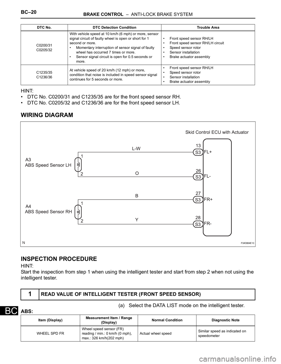
• DTC No. C0200/31 and C1235/35 are for the front speed sensor RH.
• DTC No. C0205/32 and C1236/36 are for the front speed sensor LH.
WIRING DIAGRAM
INSPECTION PROCEDURE
HINT:
Start the inspection from step 1 when using the intelligent tester and start from step 2 when not using the
intelligent tester.
(a) Select the DATA LIST mode on the intelligent tester.
ABS:
DTC No. DTC Detection Condition Trouble Area
C0200/31
C0205/32With vehicle speed at 10 km/h (6 mph) or more, sensor
signal circuit of faulty wheel is open or short for 1
second or more.
• Momentary interruption of sensor signal of faulty
wheel has occurred 7 times or more.
• Sensor signal circuit is open for 0.5 seconds or
more.• Front speed sensor RH/LH
• Front speed sensor RH/LH circuit
• Speed sensor rotor
• Sensor installation
• Brake actuator assembly
C1235/35
C1236/36At vehicle speed of 20 km/h (12 mph) or more,
condition that noise is included in speed sensor signal
continues for 5 seconds or more.• Front speed sensor RH/LH
• Speed sensor rotor
• Sensor installation
• Brake actuator assembly
1READ VALUE OF INTELLIGENT TESTER (FRONT SPEED SENSOR)
F040884E10
Item (Display)Measurement Item / Range
(Display)Normal Condition Diagnostic Note
WHEEL SPD FRWheel speed sensor (FR)
reading / min.: 0 km/h (0 mph),
max.: 326 km/h(202 mph)Actual wheel speedSimilar speed as indicated on
speedometer
Page 2391 of 3000
BC–24BRAKE CONTROL – ANTI-LOCK BRAKE SYSTEM
BC
OK
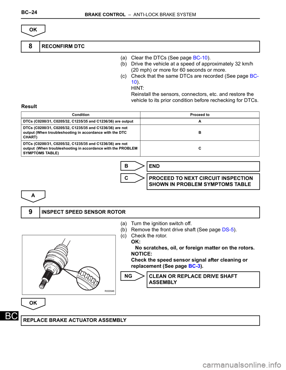
(a) Clear the DTCs (See page BC-10).
(b) Drive the vehicle at a speed of approximately 32 km/h
(20 mph) or more for 60 seconds or more.
(c) Check that the same DTCs are recorded (See page BC-
10).
HINT:
Reinstall the sensors, connectors, etc. and restore the
vehicle to its prior condition before rechecking for DTCs.
Result
B
C
A
(a) Turn the ignition switch off.
(b) Remove the front drive shaft (See page DS-5).
(c) Check the rotor.
OK:
No scratches, oil, or foreign matter on the rotors.
NOTICE:
Check the speed sensor signal after cleaning or
replacement (See page BC-3).
NG
OK
8RECONFIRM DTC
Condition Proceed to
DTCs (C0200/31, C0205/32, C1235/35 and C1236/36) are output A
DTCs (C0200/31, C0205/32, C1235/35 and C1236/36) are not
output (When troubleshooting in accordance with the DTC
CHART)B
DTCs (C0200/31, C0205/32, C1235/35 and C1236/36) are not
output (When troubleshooting in accordance with the PROBLEM
SYMPTOMS TABLE)C
END
PROCEED TO NEXT CIRCUIT INSPECTION
SHOWN IN PROBLEM SYMPTOMS TABLE
9INSPECT SPEED SENSOR ROTOR
R000948
CLEAN OR REPLACE DRIVE SHAFT
ASSEMBLY
REPLACE BRAKE ACTUATOR ASSEMBLY
Page 2452 of 3000
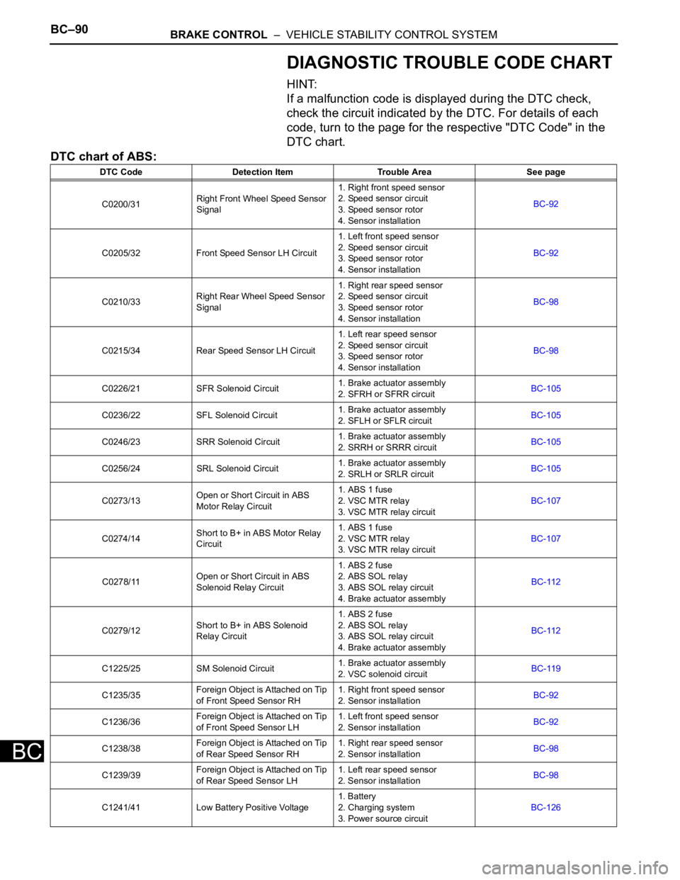
BC–90BRAKE CONTROL – VEHICLE STABILITY CONTROL SYSTEM
BC
DIAGNOSTIC TROUBLE CODE CHART
HINT:
If a malfunction code is displayed during the DTC check,
check the circuit indicated by the DTC. For details of each
code, turn to the page for the respective "DTC Code" in the
DTC chart.
DTC chart of ABS:
DTC Code Detection Item Trouble Area See page
C0200/31Right Front Wheel Speed Sensor
Signal1. Right front speed sensor
2. Speed sensor circuit
3. Speed sensor rotor
4. Sensor installationBC-92
C0205/32 Front Speed Sensor LH Circuit1. Left front speed sensor
2. Speed sensor circuit
3. Speed sensor rotor
4. Sensor installationBC-92
C0210/33Right Rear Wheel Speed Sensor
Signal1. Right rear speed sensor
2. Speed sensor circuit
3. Speed sensor rotor
4. Sensor installationBC-98
C0215/34 Rear Speed Sensor LH Circuit1. Left rear speed sensor
2. Speed sensor circuit
3. Speed sensor rotor
4. Sensor installationBC-98
C0226/21 SFR Solenoid Circuit1. Brake actuator assembly
2. SFRH or SFRR circuitBC-105
C0236/22 SFL Solenoid Circuit1. Brake actuator assembly
2. SFLH or SFLR circuitBC-105
C0246/23 SRR Solenoid Circuit1. Brake actuator assembly
2. SRRH or SRRR circuitBC-105
C0256/24 SRL Solenoid Circuit1. Brake actuator assembly
2. SRLH or SRLR circuitBC-105
C0273/13Open or Short Circuit in ABS
Motor Relay Circuit1. ABS 1 fuse
2. VSC MTR relay
3. VSC MTR relay circuitBC-107
C0274/14Short to B+ in ABS Motor Relay
Circuit1. ABS 1 fuse
2. VSC MTR relay
3. VSC MTR relay circuitBC-107
C0278/11Open or Short Circuit in ABS
Solenoid Relay Circuit1. ABS 2 fuse
2. ABS SOL relay
3. ABS SOL relay circuit
4. Brake actuator assemblyBC-112
C0279/12Short to B+ in ABS Solenoid
Relay Circuit1. ABS 2 fuse
2. ABS SOL relay
3. ABS SOL relay circuit
4. Brake actuator assemblyBC-112
C1225/25 SM Solenoid Circuit1. Brake actuator assembly
2. VSC solenoid circuitBC-119
C1235/35Foreign Object is Attached on Tip
of Front Speed Sensor RH1. Right front speed sensor
2. Sensor installationBC-92
C1236/36Foreign Object is Attached on Tip
of Front Speed Sensor LH1. Left front speed sensor
2. Sensor installationBC-92
C1238/38Foreign Object is Attached on Tip
of Rear Speed Sensor RH1. Right rear speed sensor
2. Sensor installationBC-98
C1239/39Foreign Object is Attached on Tip
of Rear Speed Sensor LH1. Left rear speed sensor
2. Sensor installationBC-98
C1241/41 Low Battery Positive Voltage1. Battery
2. Charging system
3. Power source circuitBC-126
Page 2456 of 3000
BC–94BRAKE CONTROL – VEHICLE STABILITY CONTROL SYSTEM
BC
DESCRIPTION
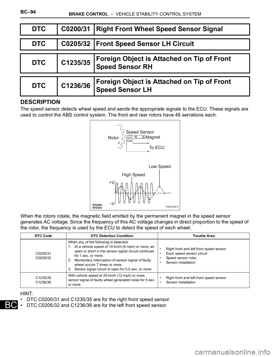
The speed sensor detects wheel speed and sends the appropriate signals to the ECU. These signals are
used to control the ABS control system. The front and rear rotors have 48 serrations each.
When the rotors rotate, the magnetic field emitted by the permanent magnet in the speed sensor
generates AC voltage. Since the frequency of this AC voltage changes in direct proportion to the speed of
the rotor, the frequency is used by the ECU to detect the speed of each wheel.
HINT:
• DTC C0200/31 and C1235/35 are for the right front speed sensor.
• DTC C0205/32 and C1236/36 are for the left front speed sensor.
DTC C0200/31 Right Front Wheel Speed Sensor Signal
DTC C0205/32 Front Speed Sensor LH Circuit
DTC C1235/35Foreign Object is Attached on Tip of Front
Speed Sensor RH
DTC C1236/36Foreign Object is Attached on Tip of Front
Speed Sensor LH
DTC Code DTC Detection Condition Trouble Area
C0200/31
C0205/32When any of the following is detected:
1. At a vehicle speed of 10 km/h (6 mph) or more, an
open or short in the sensor signal circuit continues
for 1 sec. or more.
2. Momentary interruption of sensor signal of faulty
wheel occurs 7 times or more.
3. Sensor signal circuit is open for 0.5 sec. or more.• Right front and left front speed sensor
• Each speed sensor circuit
• Speed sensor rotor
• Sensor installation
C1235/35
C1236/36With vehicle speed at 20 km/h (12 mph) or more,
sensor signal of faulty wheel generated noise for 5 sec.
or more.• Right front and left front speed sensor
• Sensor installation
F000010E12
Page 2462 of 3000
BC–100BRAKE CONTROL – VEHICLE STABILITY CONTROL SYSTEM
BC
DESCRIPTION
Refer to DTCs C0200/31, C0205/32, C1235/35 and C1236/36 (See page BC-92).
HINT:
• DTC C0210/33 and C1238/38 are for the right rear speed sensor.
• DTC C0215/34 and C1239/39 are for the left rear speed sensor.
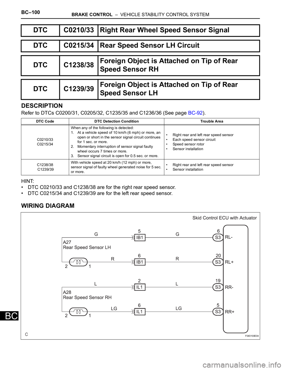
WIRING DIAGRAM
DTC C0210/33 Right Rear Wheel Speed Sensor Signal
DTC C0215/34 Rear Speed Sensor LH Circuit
DTC C1238/38Foreign Object is Attached on Tip of Rear
Speed Sensor RH
DTC C1239/39Foreign Object is Attached on Tip of Rear
Speed Sensor LH
DTC Code DTC Detection Condition Trouble Area
C0210/33
C0215/34When any of the following is detected:
1. At a vehicle speed of 10 km/h (6 mph) or more, an
open or short in the sensor signal circuit continues
for 1 sec. or more.
2. Momentary interruption of sensor signal faulty
wheel occurs 7 times or more.
3. Sensor signal circuit is open for 0.5 sec. or more.• Right rear and left rear speed sensor
• Each speed sensor circuit
• Speed sensor rotor
• Sensor installation
C1238/38
C1239/39With vehicle speed at 20 km/h (12 mph) or more,
sensor signal of faulty wheel generated noise for 5 sec.
or more. • Right rear and left rear speed sensor
• Sensor installation
F040100E04